Roadbed Bricks – Round Two

We finally got around to the second pour of the roadbed bricks. The first pour was not the best, and for a number of reasons. First was the quality of the form and the 3D printed mold inserts used to shape the concrete into a roadbed profile. Second, and more importantly, the quality of the actual concrete mix itself.

The form itself held up well, but the sides need to be tighter against the bottom if we’re going to try a wetter mix. Breaking down the form after the first pour reveals enough of the mix managed to get into the gaps between the sides and bottom. Gaps large enough that the concrete needs cleaned off the pieces before the form can be reassembled.

Closing those gaps is easy, just add more screws between the ones already there. The 3D printed profile molds now fit snugly as well, which should help hold the 3D printed dividers in place better than the first time around. The problem the first time around was the dividers moved on us, probably because of using the brick trowel to work the mix into the form and breaking them loose.

Ready For Second Pour

Fitting the molds and dividers in place takes the same amount of hot melt glue this time around as it the first time, one stick. That’s a dot on each of the four corners on the molds themselves and two or three dots on each divider. Somehow it seems more sturdy than the first time. Here’s hoping…

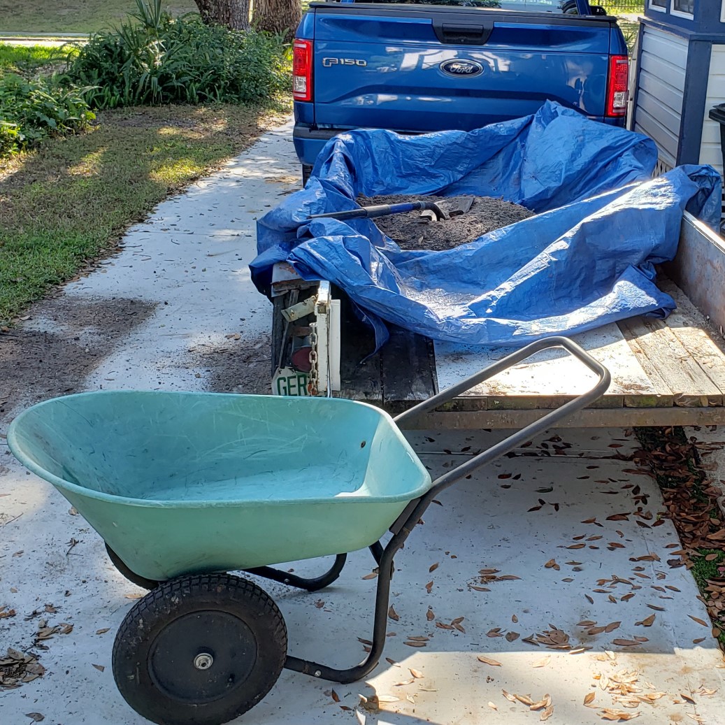
The weather is still pleasant enough to sit outside on the deck this time of year while we prepare the form for the pour. As you can see, the railing provides a suitable work surface for assembly. It can also slide back and forth on the railing as needed. The added bonus of easy access for Rocket to bring the Jolly Ball makes it even more enjoyable to sit outside in the Barkyard.

Enjoying it while we can. It won’t be long before the oppressive heat will keep us indoors all but early mornings and late evenings. We’ve already had a few record breaking days recently in the 98°-99° range. Soon it will be every day in the upper nineties, without relent, until Fall.

Ready To Mix

Time To Mix

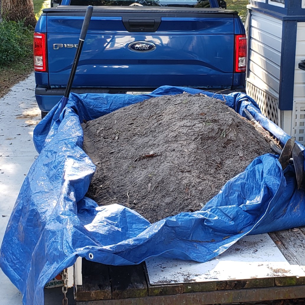
Now that the form is ready, it’s time to mix the concrete. The first time around, we used ~5 quarts of water, not quite twice the maximum of three quarts recommended on the bag. This time we’re mixing it wetter, “soupy” is the term, “Thick as a milkshake, but not so thick that you can’t suck it up with a straw.” Now the only problem is how to translate that into quarts of water per 80# bag of concrete.

Starting with 6 quarts, the mix is still too “dry”, as in not wet enough for all the mix to be easily incorporated. Adding another quart still isn’t enough. One more quart makes it a total of 8, and finally wet enough to call “soupy”. Beginning to wonder if they meant three gallons and not three quarts. After all, eight quarts is two gallons.

A few more quarts would make a fairly thin mix, but still workable if pouring. Maybe nine quarts next time? Let’s not count the chickens before they’re hatched. It’s certainly something to consider, but let’s see how this batch turns out before making more changes. It would be nice if this batch wasn’t so crumbly like the first batch for sure.

“Soupy” Mix Ready To Pour

Time To Pour

Well now we know eight quarts equals soupy. This time all it takes to fill the form is to shovel the mix into it. No working the mix into the form is required. It’s certainly hard not to be sloppy though! Each shovelful fills about two brick “slots”. Screeding the mix toward the next empty slot helps to level off with the top of the form.

It helps to angle the shovel toward the middle of the form to keep from pushing the excess mix over the edge and onto the driveway, but there’s no amount of careful that can prevent even a little spillage. We’ll wash that away with the hose when we’re done. It also helps to turn the mix over a few times before the next shovelful to keep the water from floating up and separating from the mix.

It’s about this point I remember I never sprayed the form with WD-40 as a release agent, even though I reminded myself twice before starting. Oh well. Too late now! Guess we’ll find out how much we really need a mold release agent. Hopefully it won’t cause too much trouble.

Round 2 Pour Complete

Once the pour is complete, it’s time to clean off the driveway, starting with shoveling the excess mix off of it. Next is a good wash down with the hose to push any remaining concrete off the edge of the driveway, carefully avoiding the fresh pour.

Now We Wait

Nothing left to do but wait for the pour to setup enough to remove from the form. Because the first pour was so crumbly, we’re waiting longer than a day. Besides, it’s way too hot the next evening to even think about doing anything with this latest pour. I do saturate the concrete with water to help keep it hydrated, but it will have to wait until tomorrow.

I was curious to see if the lack of a mold release agent will keep the concrete from pulling away from the sides like it did the first time. I was surprised to see that not only did it NOT keep the concrete from pulling away from the sides, it actually caused a jagged separation line, like part of the concrete wanted to stick to the sides while the rest pulled away from it.

It’s disappointing to say the least. I’m wondering if maybe I should have worked the mix into the form better. Maybe the mix didn’t fully fill the form, leaving it weak enough to separate in that jagged fashion. Doesn’t quite explain why it did it along one side and not the other though.

Disappointing Results Without Mold Release Agent

Mixed Results

Noting the telltale cracks above the dividers, it’s time to release this batch of bricks from the mold. Taking most of my lunch hour to remove them, I drag the form through the gate onto the back stoop, where I can sit and work on it. The bricks fall right out of the form one by one, splitting cleanly along the crack at the dividers without fail.

But I find another problem related to the lack of a release agent. While the bricks may be popping right out, the 3D printed molds are sticking to them like glue. For the most part, the dividers pop off without issue. All but two. Those crack along the ear on one or the other, snapping apart at the ear that’s still stuck to the concrete.

It takes quite a bit more force to pry those 8″ molds loose from the concrete though. It acts like a vacuum tight fit, where once the seal is broken, the rest of it peels right off. But even those suffer damage from overstressing the glued joints, often splitting the joint, sometimes for the full length. A number of them are now separate pieces again and will need to be reassembled.

Lack Of Release Agent Causing Breakage Of 3D Printed Molds

Better Results

While these bricks are crumbling along the jagged separation line, they are NOT crumbling anywhere else. The bricks from the first attempt would have broken with the amount of force it took to remove the molds from this time. These bricks have much more strength. They’re holding up well to the strong arm handling.

In fact, they’re resisting my attempts to trim where the dividers didn’t quite reach the top of the form. That’s one change we’ll be making for the batch. I’ll need to print a couple of replacements for the broken ones anyway.

Another thing that worked quite well was the placement of the dividers and they stayed where I put them. Not working the mix into the form with the brick trowel seems to have saved us from having misshapen bricks. They also peeled right off with the bricks and didn’t require removing the sides of the form like the first batch.

The best part is the 100% yield! All 12 bricks came right out of the form and none of them are cracked or broken. I can even read the writing from the embossed text on the dividers! Round two is a success! We’ll give them the rest of the week to cure and put this idea to the test.

Comparison Of First Batch and Second Batch

Time To Lay Bricks

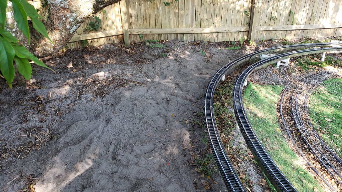
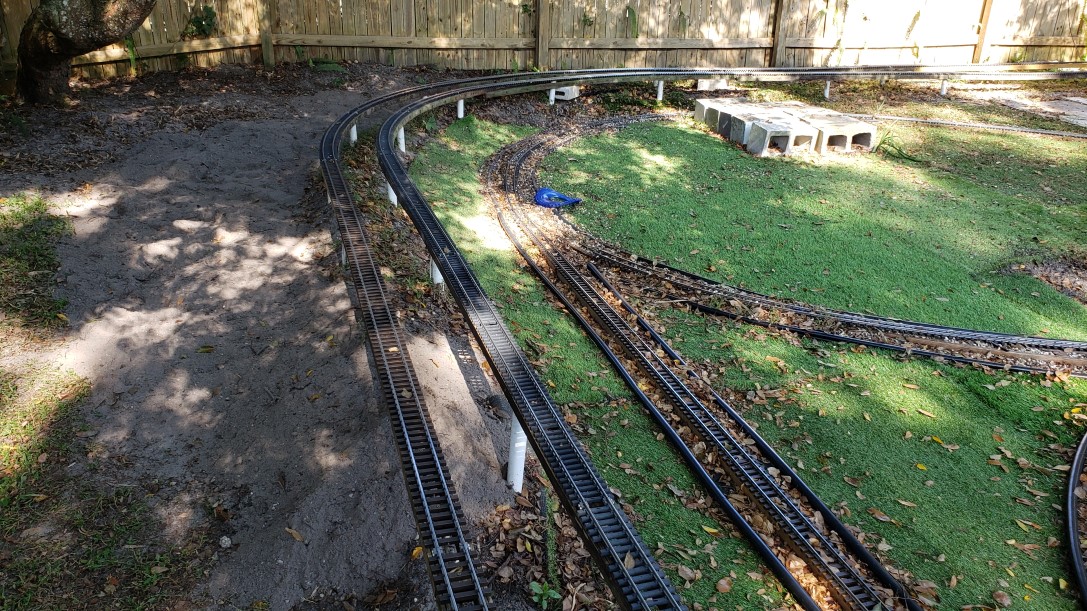
Well, almost. First we need to clear a path for the bricks to sit on. The two concrete blocks with the chunk of 2×6 across them is to protect the puppies’ paws from the sharp ends of the track. We’ve been losing ground lately with three puppies pounding things to pieces, having to remove more and more track to keep it from getting damaged and them from getting hurt on what’s left.

In fact, all that’s left are the stringers that survived where the track used to lay. This “experiment” is meant to mitigate that damage and provide a means to protect the track and the pups. Time to pull the stringers out of the way and replace them with the roadbed bricks.

It only takes removing a few screws and the first stringer is free, after releasing it from the join with the next stringer of course. Now we need to lay out the bricks and cut the turf along the edges to make room for them. But first we need to rake all those leaves out of the way!

A leaf blower will just make a huge mess everywhere and a big rake won’t fit, so it’s a good thing we have a “mini” rake that’s about as wide as the bricks are. It makes quick work of moving just the leaves we want out of the way. Pretty handy. Not our first either. IIRC this is our third.

Replacing The Stringers With Roadbed Bricks

Bumps In The Road(bed)

Anyway, time for the Dremel saw. It does an adequate job of cutting the turf without much effort. If there is a single complaint, it would be the lackluster locking mechanism for the foot. It’s a flip / twist handle that gets cinched down to lock the foot and set the depth of cut, but the damned thing is at its end of travel before it actually tightens, constantly coming loose!

It would do a great job if the depth of cut didn’t need constant attention. You may think you’re cutting, but guess what? That damned foot is once again set to not cut at all! This time it’s taking two, three, even four tries to get a cut, and the cuts are now crooked and ragged. But enough “belly aching”, it’s just another unnecessary annoyance due to poor quality control.

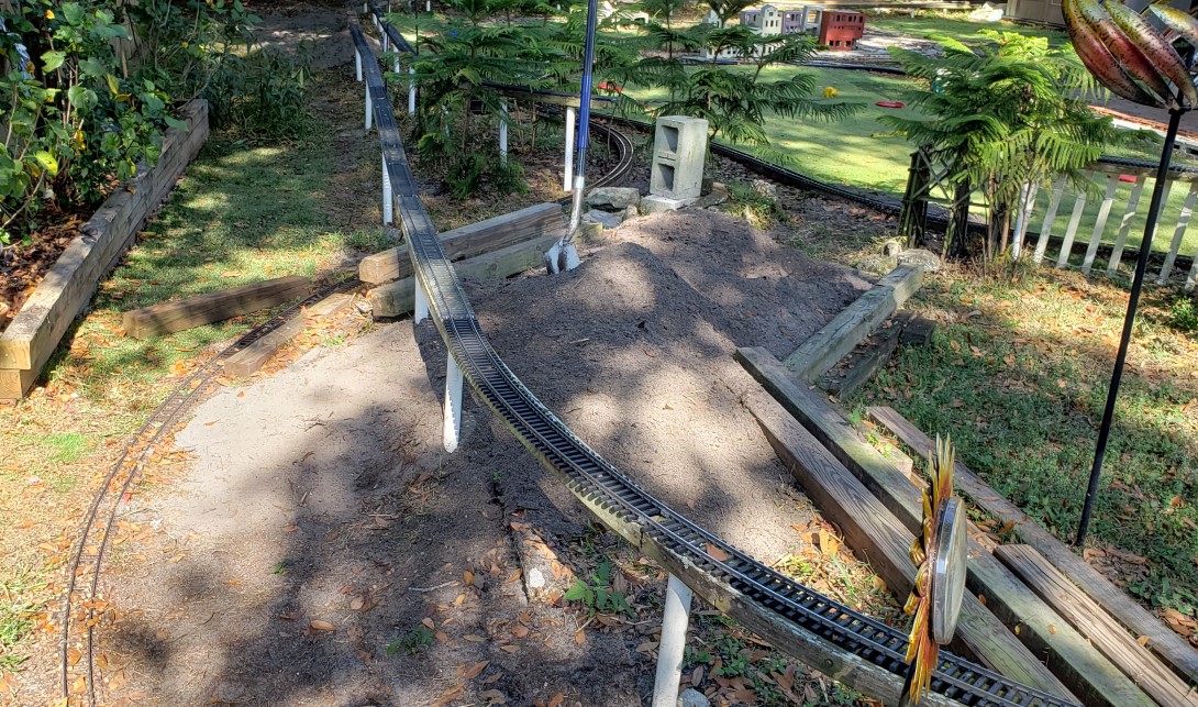
Part of the problem is uneven terrain and cutting along the edge of the bricks, laid out in the circular pattern where they’ll sit. That uneven terrain is also causing an “elevation” problem with the first few bricks after the track leaves the 4×4 roadbed. The problem is twofold. First is having to make up for the height of the 4×4 itself and second is the 4×4 is sitting proud of where it should.

You can see how the track is dangling off the end of the 4×4 in the picture above. Those PVC pipe risers were also in the way and have been removed. Because the first batch of bricks is so crumbly, it begs the idea of crumbling them into “rubble” to restore the elevation needed.

Time To Play (Jolly)Ball Dad

Rocket is helping too, making sure to pace me by “pestering” me to throw the Jolly Ball… Constantly! But that’s okay. He didn’t get much play time this last week because we’ve been so busy with the latest “emergencies” at work. “We must overreact immediately!” comes to mind. Can’t wait to retire and kiss all that constant chaos goodbye!

On the plus side working remotely still has its advantages. After all, I was able to spend my lunch hour to get these bricks out of the form and ready to work with now. We get to stay home with the pups so they don’t have to go to “Doggy Daycare”, and we still get to play with them during the day, even if it’s not as often as they’d like.

Crumbling Infrastructure

What was originally a disappointment is quickly turning into an advantage, an opportunity to use those crumbly bricks in a way they were not originally intended. Where’s my hammer? My favorite place. Somewhere. Oh well, hopefully the “mini” hammer will do the trick. Let’s finish the job of crumbling them into rubble.

Rocket Inspects My Work Waiting For Me To Throw The Ball

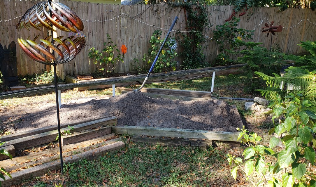
The idea is to crumble them the rest of the way and use them as fill to make up the height difference at the end of the 4×4 roadbed. One won’t be enough. Turns out even two isn’t enough. Three? Nope. More. In the end, all but four of them are pulverized to become fill beneath those four that remain. But not all at once.

I start with a first course of crumbled bricks, spreading it even and level until more is needed. Then start the next course, levelling it, and so on. As I sit there pounding those bricks into rubble, I continue to test fit until pleased with the progress.

One thing’s for sure, that 4×4 needs to sit down in the ground at least another ½”, if not more. The track doesn’t like bending over the edge of that 4×4 much. Side to side, sure. But not a sudden drop of ½” or more. A concrete block coerces it into position for now. Maybe the tie strips can be adjusted to leave an opening so the track will sit down over the end of the 4×4.

Close Up Of Troublesome 4×4

Lessons Learned

  • DO NOT FORGET THE MOLD RELEASE!
  • Tamp the mix into the form with the shovel to ensure complete fill, then screed.
  • Vibrate the mix to remove trapped air and eliminate gaps.
  • Make the dividers extend all the way to the top of the form (redesign).
  • Increase the font size for the end marks or just assume one size fits all?

The first two are fairly self explanatory, plus I covered them earlier. What I didn’t cover was the amazing amount of detail the wetter mix captured. I can see the layer lines from 3D printing the molds in the concrete! The only thing that spoils it is air bubbles and “inclusions” where the concrete didn’t quite fill the gaps. Need to try vibrating the form once tamped and screeded next time.

Making the dividers tall enough to meet the tops of the 1×4 sides of the form should avoid having to snap off the jagged excess by hand to make the ends flush. That means a redesign of the divider model then printing more with the new STL. Some of them broke and need replaced anyway.

While we’re at it redesigning the dividers, it’s time to think about a one size fits all approach. Rather than having bricks of varying degrees of curvature and having to stock many different types, including tangent, why not have one that can be used for everything? The difference between the various curves is at most 3.75°, so a small gap one way or the other will barely be noticeable.

Another bonus is tangent track can be accommodated by alternately rotating the bricks 180°, such that the angles point left, then right, alternating to effectively create a straight section. If you look close in the picture with Rocket inspecting things, you’ll see I had to do that in a few places to help adjust accumulated error in the curvature, a straight section as part of a curve.

More to come, so stay tuned.


Concrete Roadbed – Initial Brick Version

We finally threw in the towel! Using wood stringers as a roadbed is just not working out. It’s been one thing after another using wood. The first setback was rot. We finally found the answer to that, but the next thing was keeping the track fastened to the stringer – with a couple puppies constantly pounding on it. Even adding screws every 8″ didn’t help! We now have track with much larger holes in the ties where the screw heads pulled through them.

Fast forward. We’ve added yet another puppy to the team, Jasper. Alright, three full sized German Shepherds! None of them are little puppies anymore. We were barely keeping ahead of things with two puppies pounding the track into the ground. But now we’re fighting a losing battle with three, we’ve been removing track, not adding it. And that’s moving in the wrong direction!

Concrete roadbed should certainly hold up to the constant pounding, if sidewalks and driveways are any indication that is… Beyond that, the idea is to shape the concrete with a center depression, a “well” of sorts, that will “cradle” the track. The only question left is whether molding roadbed bricks will work better than forming concrete then screeding the profile.

After all the trouble we went to on the forms for the trial version of casting concrete roadbed, only to be thoroughly disappointed with the results, we’re hoping the roadbed brick approach will be more successful. This time around we’re counting on the forms to produce a much more defined profile and a better defined well for the track to sit in.

3D Printed Casting Molds for Curved Segments

The Design

The molds are all 3D printed a “standard” 8″ in length, with a ballast profile. A picture is worth a thousand words. At the top of the diagram are the individual parts on the right and how they are assembled into a casting mold, or form, on the left. At the bottom are the “dividers” for the various diameter curved segments.

The molds are designed with the deep well profile, the center part of three. The other two are meant to emulate a standard ballast profile. The three parts are glued together, held in place with three of the “assembly jigs”, seen beneath the assembled 8″ brick mold. This assembled mold consists of a 2×6, with sloped 1×4 sides, and the assembled 3D printed parts set inside the “U” shape formed by the lumber pieces.

The dividers are designed for the three different curved track segments we use, 10′, 14′, and 20′ diameters. Each has a different angle and number of segments for the associated diameters and there are left and right version for each diameter. You can see the text slightly raised above the divider body, and mirrored so as to emboss the brick casting correctly. Can’t wait to see if it works.

The relationship between the three designs for 10′, 14′, and 20′ diameter curves are shown in comparison below. A quick explanation will help to understand the information it contains. Obviously the arrangement of the bricks into the three different curves demonstrates the 8″ segmentation, but not so obvious is the arrangement with respect to the track segments.

Relationship Between Various Roadbed Brick Curved Segments

The Explanation

Note there are two angled guidelines. One is 22.5° with respect to horizontal and the other 30°. These angles are related to how many track segments required to complete a circle of track. For 14′ and 20′ diameter circles, 16 pieces are required, 22.5° per piece. The 10′ diameter circle requires only 12, 30° per piece.

Let’s look at the 10′ curve to begin with. Counting the number of bricks required to complete the curve to the 30° mark, we count four. Observe that while the nominal size is 10′, it’s really 59.055″ because Aristocraft decided to try to stay compatible with European track makers. Doing the math, one of those track segments is ~30.92″ long, just shy of 32″… That’s roughly four 8″ bricks.

If we round off to ~31″, we need to lose roughly ¼” per brick, making them 7¾” long. Note that these dimensions are along the centerline of the circle. Adding the extra 1¾” to get to the outside edge of the ties is ~31.84″, which rounds nicely to 32″.

Now consider the 14′ diameter curve. This time we’re using the 22.5° guideline to count bricks. Again four are required for a single segment of track. And again, it’s not really 14′, but 82.677″. That yields a length of ~32.467″, again roughly four 8″ bricks, only this time we add about 1⁄8″ to each brick.

The 20′ (118.11″) diameter curve is similar, using the 22.5° guideline except now we count six of those 8″ bricks to match a segment of track, ~46.382″ in length. Again we subtract roughly ¼” per brick, making them 7¾” long. By now it should be abundantly clear why the 8″ length was chosen.

Roadbed Brick Casting Form Ready for Pour

The Decision

If all that math hasn’t turned your brain to mush, the key point is all the bricks are roughly the same length, with roughly the same angle on their ends. The angles range from 3.75° to 7.5°, but they must be halved to obtain how much the end angle diverts from perpendicular with respect to the centerline. It’s 1.75° to 3.75°, which is large enough to be discerned with the naked eye.

So let’s start with the 20′ bricks, the ones with the smallest end angle of 1.75°, and see just how noticeable it is. While the picture shows an independent 8″ mold for each brick, a more practical approach starts with an eight foot or ten foot long 2×6, and matching length 1x4s. The ten foot length is preferred since an 80# bag of concrete mix will just fill it, give or take.

Unfortunately all we have on hand is eight footers, but that just means a bit of wasted material, roughly three bricks worth. The thought is to attach the 1×4 sides in a sloping fashion to provide enough draft that the casting will slide out of the form. The 3D printed ballast profile has a built in draft angle spacer effect, this is it’s slightly wider than the 2×6, which should cause the 1x4s to splay out by just enough.

Sounds good anyway. In practice, putting this together demonstrates how imprecisely everything actually fits. Every single piece of wood is warped. Trying to precisely fit the dividers at the precise angle is an exercise in futility. At this point, those 3D printed parts are held in place with hot melt glue. The main 8″ piece gets a dab in all four corners and the dividers get a bead along both edges. That rechargeable hot melt glue gun sure did the trick though!

Close Up of the Form Ready to Pour

The Pour

The directions call for 3 quarts of water for the entire 80# bag. Despite using one of the measuring buckets to dispense three quarts exactly, the mix is too dry. Adding another quart results in a mix that’s still too dry. Not quite another quart and now the mix seems too wet. This time I used the correct (read larger) mixing tub and still manage to spill some of the mix over the edge.

Oh well, I’m more worried about getting it mixed and tamped into the form, which lays across the driveway just outside the gate. About the only place I can put it that’s pretty much level and leave it sit for a few days. Tamping the mix into the form then screeding it off with the same square shovel floats quite a bit of moisture from the mix.

I should mention I liberally sprayed WD-40 over the entire form as a mold release agent before mixing the concrete. Continuing to shovel the mixture into the form until it’s full, the extra goes in the spot along the drive where the old well used to be.

There’s quite the story about having the trees removed from the Barkyard and the crane’s front wheel “falling” into it up to the axle. We filled it in with chunks of the trees and old scrap concrete and whatever was available at the time, but over time it’s slowly settled, leaving a void beneath the edge of the drive.

The Cure

I think my phone is messing with me. I’m pretty sure I took pictures of the pour right after and the next day. Guess what? No pictures! GRRR!!! Looks like I need to get in the habit of checking afterward. Seems like this isn’t the first time it’s happened either. Guess I’ll have to describe what I saw…

Just hours after the pour, the edges had shrunken back from the sides of the form already! That seems odd. It’s definitely unexpected. The next morning, I noticed thin cracks had formed above the divider locations. At first I was worried they didn’t stand quite as tall as the 1×4 sides, but figured the stress on the small amount of concrete would make it easy to split the bricks apart anyway.

Removing one of the sides of the form later in the day, I noticed the concrete itself was still quite crumbly, more unexpected oddness. I did expect where the concrete seeped through the cracks would be weak, but not the entire brick. When the brick on the end started to crack and split into pieces trying to remove it from the form, it was decided to use a different approach.

Perhaps just rolling the entire form over with the other 1×4 side still attached would give them more support and aid in removing the entire form all at once. Considering how some of the dividers stayed with the wood and tried to pull the bricks alongside with them, that was probably a mistake too.

All in all, nine of the twelve bricks survived the rough handling. Two of them pretty much crumbled when exposed to any sort of stress. Another split along the entire length at the edge of the well. The “crumbles” got thrown in the spot along the drive where the old well used to be on top of the extra concrete.

The Nine Survivors out of Twelve

The Result

While 100% perfection was not the expectation the first time through, a 75% yield of lesser quality, low strength bricks is less than pleasing. Worries that too much water was used soon turned into questioning whether not enough water was added, leaving the mix dry and crumbly.

If you’ve ever seen one of those videos where they compare the strength of “dry cast” concrete, tamped in the forms dry, then wet afterward, to casting already mixed wet concrete, the bricks had the strength of the dry cast method. Hopefully it’s as simple as that, mix it “soupy” next time and compare the results.

Perhaps a slump test would prove more useful, but it’s easier to just measure out the same amount of water per 80# batch and go with that. Once the magical amount is known that is. Nick says mix it soupy, so soupy it is for the next round.

The dividers sticking is another issue to be dealt with. A redesign may be in order both to help better align them without the need for tools and to eliminate the need to hot glue them in place at all. Aligning the divider angle within the accuracy of even a few degrees is difficult without some sort of alignment tool.

Hot melt glue is the quick and dirty method of “loosely” assembling the mold parts into the forms. There were a few that had too much hot melt and refused to let go. Clean up is a pain too. Normally the blobs of hot melt will pop right off with a bit of persuasion. Too much persuasion for wet fingernails!

Crumbling Lengthwise Split at the Well

The Comparison

As far as the amount of work involved, the most work is mixing up the concrete by hand with a shovel, but that much is required using either method. Let’s compare the two methods, which takes more work, and the pitfalls of each, starting with the trial version first.

By far the method involving the most work is setting the forms in the ground and screeding the profile into the wet concrete. It takes days just to get everything formed proper and level for pouring. If the mix is too dry, we know using a screed tool won’t work, it needs to be a trowel. And that trowel’s a guess since it hasn’t been tried. If the mix is too wet, the profile will slump regardless of what method is used to create it.

Using the casting molds approach is much simpler to prepare for pouring, using a dab of hot melt glue on each of the four corners to hold the mold to the 2×6 form base. A couple more dabs of hot melt to hold the dividers in place and we’re off to the races. The best part is the only screeding required is to level the top of concrete with the sides of the form.

As far as pitfalls, the formed in the ground method is almost as much of a pain to disassemble and it was to assemble. The form slats are held to the stakes by one small brass screw, removed one at a time, the same way they went in. Granted, disassembly can be accomplished in hours compared to days to assemble. At three days for every ten feet of right of way, it will take forever to finish.

For the brick molds, it takes a few hours to clean them up too, washing away the remaining concrete residue and removing all those hot melt globs. Those raised letters are nearly impossible to read. Vibrating the form may have helped alleviate some of the small voids and filled in around the letters more, but just working the mix into the form with the shovel did a pretty good job otherwise.

Cleaned Mold Parts Ready for Reassembly

Next Steps

The advantage goes to the brick mold. Those parts can be turned around and assembled into a form ready to reuse in about an hour. The first thing to try is a wetter mix, perhaps even vibrating the form too. If that fixes the voids and the strength issues, then maybe a few tweaks on the dividers. It would be nice if they were thicker and snapped in place instead of needing hot glued.


Office Refit

This post is a bit off the beaten path compared to other posts about the Barkyard itself. Why a post about the office? We’re refitting “Data Central”, the heart of Barkyard designs, gadgets, and posting of course! Just about everything associated with the Barkyard starts here in Data Central. An idea starts here and grows here. Whether it’s online research or Arduino coding, it all starts here.

What used to be drawn up with pencil and paper is now captured electronically, and has been for years now, decades even. And over those years, the applications used have changed, many so old they are no longer supported by modern operating systems. For example, while my favorite Windows 95/98 programs continued to run on Windows XP, they absolutely will not run on Windows 10 or 11.

What does all this computer speak have to do with refitting the office? Everything. Within reach of my office chair are two servers and three laptops. The two servers share physical keyboard, mouse, display, and USB devices via a KVM switch. While not really necessary, it certainly comes in handy when we can’t reach the Internet for whatever reason, when I can’t use Chrome Remote Desktop to access the other server.

The Start of Good Things To Come

Computers Are Great… When They Work!

These posts are created on the new computer, with a brief hiatus while the failed boot drive was replaced. Short version is just before the year warranty ran out, the 2TB SSD failed miserably and the computer refused to boot. I put in a warranty claim, then waited months before I was finally able to talk to someone who cared, and he express shipped a replacement SSD to me.

What’s the kicker? By the time the normal warranty chain played out, they ended up sending me another replacement SSD a few weeks later! As much as I complained about their cumbersome and exasperating support process, or lack thereof, it serves as a striking example of how not to do things. But it paid off for me in the end! I’m still chuckling about it.

Whether designing a new gadget or coding a new Arduino sketch or writing a new post or just plain research for the Barkyard, computers are a vital part of it. The older server provides large data storage and backup, both for applications and data. The new server is optimized to compose and render videos, perform CAD/CAM, and provide enough local storage to save all the collective research.

A Bit of History

There are two work cells, one devoted to personal servers, the other a gadget work cell “around the corner” from the first, now shared with work computing. That’s where the laptops come into play. When I started back to work more than two years ago, I needed another computer work space, separate from my personal computing space, for the work laptop and its associated devices and monitors.

The original gadget workspace was a set of cabinets, one 42″ and one 36″, that supported a ¾” cabinet grade plywood top. The 42″ cabinet forms an “L” with two more 36″ cabinets along the back wall facing the Barkyard. All in all, it’s a Galley style arrangement when the computer desk is added along the opposite wall.

I wasn’t pleased I had to share my gadget assembly and testing area with my work computing. Work by day and projects by night? Sounds good until there’s a project laid out that can’t be put “back in the box” the next morning when booting the computer and getting back to work. At least it pays the bills.

Preparing to Install the Split Unit

Original Rework

The makeshift computer work cell using the original 42″ cabinet was not optimized for computing. For that matter, it wasn’t meant for computing at all. The cabinet sat on the floor, which runs downhill toward the back wall. Originally this was the sleeping porch, now closed in and under air. In fact, it has it’s own dedicated split unit now to handle all the heat those computers and printers throw off. But I’m getting ahead of myself.

About the only thing that can be said is it’s level so things don’t roll off it. It’s home to all sorts of electronics and parts assortments and Arduino kits, haphazardly arranged on a custom shelf arrangement that was previously meant to store CD jewel cases. Thankfully the top shelf is just wide enough to hold up another set of monitors.

It doesn’t take long to realize that not only is it not optimized for computing, it’s in no way ergonomic either. The pain in my back, through my hip, and down the side of my leg is telling me something has to change. Assuming it’s constantly fighting that tendency to roll downhill since the pain is on that side. Of course, having to keep my feet up in that cabinet probably doesn’t help.

That 42″ cabinet has to go. Go where? Out. It doesn’t matter where. But that doesn’t help fix the downhill slope of the floor. The plan is to lay down a 4×4 sheet of ¾” plywood, strategically supported to keep it level. The only problem is that 36″ cabinet, but there’s nowhere for it to go. Now what? There’s just enough space to push those other 36″ cabinets along the back wall far enough to spin that 36″ cabinet around and inline with the other two.

Long story short, the floor is now a level sheet of plywood with a nice rug to cover it and the gadget workspace is now a dedicated counter supported by a set of custom brackets. Custom brackets that used to support my HO scale layout at the old house, sitting in the garage waiting to be useful again nearly as long as we’ve lived here.

Data Central Two Years Ago

The Problem

Well, there’s more than one problem, but the main problem now is the haphazard arrangement of everything in relation to everything else. There are five 27″ monitors, and no two sets of them are at the same height. The two monitors dedicated to personal computing are at just the right height off the desk, sitting atop its “Pidgeon hole” cabinet, roughly 9″ at the base. The middle of the screen is just at eye level. No neck strain.

The base of the single monitor dedicated to the surveillance system sits right on the gadget counter, but that sits about 3″ lower than the desk, about 12″ lower than the first set of monitors. And even though that counter is lower, the custom shelf arrangement holds the base of the two monitors dedicated to the work laptop at a good 6″ – 7″ higher than the personal computing set.

As if that isn’t goofy enough, the counter isn’t long enough to complete the “L” with the desk, so there’s a gaping 20″ chasm between the wall and the edge of the counter. That monitor for the surveillance system teeters precariously over the edge and the USB hub sitting next to it is always falling into the abyss. What should be a Galley style arrangement isn’t. The issue is the metal and glass shelving unit that promised to be more useful than it turned out to be. All it does is collect dust and it needs to go away too.

Another problem is the loss of storage space with the loss of that 42″ cabinet. To that end a drawer was added under the counter and between the custom brackets. But because it wasn’t well thought out when installed originally, a compromise was made. More like a complex set of pieces were needed to force the drawer and slides to fit, even after it was cut down from its original wider size. Between that and constantly banging my knees against it, that will need to be addressed as well.

The Solution

The solution to these problems and more is a refit. That is to say a retrofit to re-fit everything together in a more purposeful, organized fashion. I’ve been updating my office layout in SketchUp, mainly to try some “what ifs” without having to tear everything apart to test fit ideas. It definitely helped me figure out where that 42″ cabinet would fit, along with the rest of everything else.

I’m not going to lie. Part of that effort was to catalog and look at some “what ifs” for placing the old HO scale layout sections in a bookshelf layout arrangement, fitting and reusing the various shapes and pieces of ½” plywood sub base that’s been waiting to become useful again along with those custom brackets. But that’s on hold for now. More pressing matters to address.

More pressing matters like continually deteriorating infrastructure and soon to be installed fiber service. That’s right, it’s finally here. Nearly twenty years after we were originally promised fiber at the old house, and by the same company no less! It’s probably a good thing I didn’t know that until their trucks showed up out front or I would have told them to pound sand! But that’s another story for another time.

Not that we were unhappy with our service provider, 250MB per second download speeds are nothing to sneeze at, but we’re lucky to get 10MB – 12MB per second upload speeds. The one and only time we tried to go live failed miserably because of those limited upload speeds. With fiber we can speed less and get more, like 1GB per second down and up! In fact, we can cut our costs further by going with the 500MB per second plan.

Before Slicing and Dicing
After Slicing and Dicing
Plywood Sheet Conveniently Cut Into Shelves

The Refit

That’s the motivation for the refit, and the motivation to get the refit done now, before they come to install the fiber. So what exactly is the refit? Good question. Glad you asked. To boil it down into its most condensed form, it’s slicing up a 4×8 sheet of ¾” furniture grade plywood into dedicated shelving that solves all the disparities already listed.

  • A new counter section that not only fills the missing gap, but also adjusts the height and solves the constant knee banging.
  • A new shelf to align all the monitors at the same eye level height along with increased storage space.
  • A new shelf along the wall over the personal computing and surveillance system monitors for more storage space.

It begins with the shelf over the monitors so there’s someplace to put the Gramazon, and the track and rail cars sitting on top of the work monitors, and anything else that needs a temporary home while fitting the new counter and the other shelf. The shelves are cut 12″ deep for the 8′ length of the sheet. That leaves the remaining 24″ for the new counter. All that remains is fitting to length and capping with screen mold for a clean, finished look.

“Hidden L” Brackets

Originally I was going to make custom wooden brackets for the shelves but the more pressing need to finish before the fiber is installed put an end to that idea. Looking at various options online, I came across the “Hidden L” arrangement. Essentially a thick, flat piece of metal with an attached mounting bracket at a right angle that is partially hidden by the shelf it supports. My only concern is how much they’ll sag under load.

The Rethink

The shelf for over the monitors is shortened to 6′ to fit the available space between the wall and the door frame. Then the screen mold is glued and brad nailed into place. Finally the piece is sanded smooth and ready for placement. After attaching the brackets to the wall at every stud, 16″ on center, the shelf is set in place. I can pull the shelf down at least ½” applying a lot of force. Even though they’re rated for 100#, I imagine I could bend or break the brackets if I hung my full weight on them.

I’m pleased with the fitment and the resilience of the brackets but soon realize I forgot to cut the angled notch out of the corner for cord relief. No matter, there’s enough clearance on either end that only the fattest power cord wouldn’t fit. Considering the only power cord so far is for the amazon dot and it could fit in the space between the bracket mount and the back edge of the shelf, roughly 0.2″ thick, it’s not a big deal.

The New Counter and Monitor Shelves Waiting For Trim In The Garage

The office isn’t quite 8′ wide, roughly 90½” from the inside wall to the outside wall. The original plan was to place the counter from wall to wall with those 36″ cabinets lifted and levelled to match, mainly to allow access to the floor plywood to rework the levelling supports beneath it to firm things up. Best laid plans…

After seeing how the wooden bracket that supports the 3D printer shelf would interfere with the back runner on the cabinet and how much trouble it was trying to maneuver the new counter into place, the plan to make everything level was quickly abandoned. Cutting to fit wall to wall turns out to be a bad idea, an awful idea in fact.

After multiple back and forth trips to trim the length it’s still a bear to get the thing maneuvered into position. Short of nearly standing the thing up just so the corners clear when rotating it into place, it’s nearly impossible to clear what used to be the porch banister, still a major structure on that wall. Add to that the overhang sagging on either side of the custom brackets and we need a new plan.

The Replan

More like we need a replan. We can add another one of those custom brackets on the end by the desk, but we’re out of luck on the end over the 36″ cabinet. The decision is made. The counter will be cut to fit up to but not cover the 36″ cabinet. That is to say we’ll remove 24″ from the 90½” length. We’ll also add that third custom bracket near the inside wall to support the sag on that end.

Next step is to rework the mounts for the drawer slides. Starting with a 1×4 doesn’t give enough clearance for the contents of the drawer. The big offender is the mixer board, stashed there until needed. The idea is to leave it connected and just pull out the drawer when we want to use it. Switching to 1x6s. My knee aren’t smashing into the drawer anymore, just the corners of those 1x6s!

The new shelf for the other monitors is cut to fit wall to wall, which is still a bad idea. After multiple back and forth trips to trim the length it finally fits. The biggest issue this time is it deviates from the plan and there’s not quite enough space for the surveillance system monitor in its planned position.

New Counter and Monitor Shelf, Complete With Third Starship Liftoff!

The picture above shows the halfway point so to speak. This is the work laptop setup. On the left in the foreground, glowing green, is the new power supply for the audio amplifier. Behind that is the surveillance system, it’s PoE ethernet switch for the cameras, and the battery backup (UPS) for those and the amp. The monitors and the laptop itself have their own dedicated battery backup (off screen to the right).

The keyboard and mouse sit atop a piece of 1×6 that spans the front of the drawer and acts as a keyboard shelf. The dedicated microphone and audio amplifier for the associated speakers is visible on the right, left speaker visible on shelf to left. The surveillance system monitor has been relocated to the right side of the work monitors. Regardless of its placement, the work monitors must shift one direction or the other. Time to go back to plan.

The original plan calls for a “round the corner” fitment for the shelf on the left end, pretty much where the left speaker and Gramazon are sitting. What’s a Gramazon? Good question. Glad you asked. See that blue thing there that looks like a gramophone? The base contains my Amazon Dot 3 and the gramophone part guides sound to and from it. It’s one of the first 3D prints I made, starting with one for Ann’s Dot 2.

“Around The Corner” Shelf And New Fiber Modem/Router

Time’s Up

Because they had to locate the utilities, pull the permits, and trench in the new fiber before they could connect us, it gave us a bit of a reprieve of maybe a week or so. The picture above shows we’re still working on getting the refit finished. It didn’t stop the installation or even slow it down. Having to go through three different fiber modems set us back more than our refit, still in progress, but at least they figured out what was wrong with their system and fixed it.

You can see the fiber modem/router in the picture above, white case with a green light. I dressed out the ethernet cables from the surveillance cameras using short lengths of Velcro® looped around on itself, and the excess length coiled beneath the fiber modem. To the right of that and under the square chunk of shelf is the surveillance system (NVR) and the PoE switch to manage all the connections.

At least this time I remembered to cut the cable relief in the back corner of the shelf. Still missing is the planned angled cut on the front corner facing out of the picture. The plan called for an 18″ square piece with a 6″ triangular relief cut from the front corner. That plan was modified to avoid having to move the shelf bracket. So 16½” it is. Hopefully that will provide enough space for the surveillance system monitor to sit above it.

Installation Finished

Both the fiber modem and office refit are installed and we’re happy with both. It certainly took some doing though. What started with dropping the Internet connection a few times a day turned into swapping modems twice, each time getting worse, not better. The last attempt and we had maybe ten minutes of connection before dropping again. Totally unacceptable! Now I’m wondering if we haven’t allowed the same company to totally screw up our Internet once again.

Both Ann and I have 100% remote jobs that require a reliable Internet connection. At least Ann has an Air Card supplied with her work laptop. Me? Not so much. I had to tether through my phone until they fixed it! They had to replace some “filter” downtown at the office just blocks away from us. This played out over the course of a week or more.

I must admit, now that it’s working reliably, 540MB per second speeds both down and up is really much better than we had before. Maybe we’ll try one of those livestreams again to really test it out. It certainly was a distraction from more pressing issues, not to mention the extra stress of having to deal with it at all. Now back to the matter at hand, the refit.

Refit Installed, Monitor Shelf and Counter Shown

A place for everything and everything in its place is the ultimate goal for the refit now that the new counter and shelves are installed. Even the idea of hanging the battery backups from the underside of the monitor shelf panned out. Most of the project “pencil boxes” are back where they sat on the counter, but all the parts kits and such are still sitting in a large tub in the corner of the office, their place yet to be determined.

The picture shows one of the benefits of having a second computer space for laptops. That’s my personal laptop, but it can share the same docking station that came with my work laptop. Convenient. Very convenient. Both are ThinkPads, but my personal one has the super sized screen, which is why it’s folded down to fit on the counter. I do like having three screens for sure.

As an aside, the Windows 11 driver for the CH340 serial controller doesn’t work, but the Windows 10 version does. You’ll never guess what’s running on the new computer. Good thing I can connect the laptop and have it talk to the Arduinos that use that CH340 chip! In fact, that’s pretty much what’s going on in the picture.

New Gadgets

Speaking of Arduinos, the refit inspired a new gadget. A new lighting gadget. You can see the first cut at it above running the “Christmas Tru-Tone™” effect. A little setup first might help. The monitors aren’t the only things sitting on the desk “Pidgeon hole” cabinet. Behind the monitors at each end of the desk are a set of lamps. Those lamps have Amazon Alexa compatible smart plugs attached so I can say, “Alexa, turn on Office 1” and the lamp on the left will light.

Convenient. Much more convenient than having to run the lamp cord by hand just to find the inline switch every time I want to turn one on or off. Unfortunately, the new shelf over the monitors on the desk blocks the light from the lamps. What used to illuminate the white ceiling and cast light throughout the office now provides just a backlight to the monitors. An unwanted backlight. We need something to replace the light we lost.

Inspired by my latest lighting adventures for controlling the lithophanes, I decided to dig out those LED strip corner frames I bought years ago to use for the train station lighting. The train station we no longer have, lost when we removed the raised bed planters along the patio. Anyway, the idea is to place the corner frame along the back of the shelf over the monitors, facing toward the ceiling and out into the office.

Those corner frames have a face at 45º to either side, meant for the LED strip to stick to, and a snap in diffuser over top of it all. While I didn’t really need the scheduling additions from the lithophane lighting sketch, I did want all the updates and bug fixes that came with it. I also expanded the “build from config” feature to get us closer to not having to create a dedicated HTML page just to control all the different lighting arrangements.

I’ll save all the exciting details for a separate post. Suffice it to say that it took some doing, both in hardware and software. The end product does what I want, provide a soft backlit atmosphere for the office, perfect to see what you’re doing but not so bright that I have to squint. This picture shows the shelf over the monitors. You can also see the split unit and the Gramazon on the right.

Let There Be Light! The New Office Lighting Gadget In Operation.

Finishing Touches

If anything remains to be done it would be to apply a finish to the new shelving. I think I’ll save that for when I have a week off of work and can take the counter and monitor shelf offline long enough to stain and finish them. I can take down the shelf over the monitors pretty much anytime I want, but I’ll probably wait and do them all at once. Who knows? Maybe I’ll get motivated to stain, finish, and level those 36″ cabinets too!

I may even break this into two parts, seems kind of long winded, even to me. Let me know what you think in the comments.


Lifting The Deck

Let’s start with the obvious question, “Why lift the deck?” Good question. Glad you asked.

The main reason has nothing to do with the deck and everything to do with the dogs and the bridges… Well, what used to be the bridges.

Let’s rewind…

When we originally built the approach trestles for the Howe truss bridge, they were built 20″ tall, roughly forty scale feet tall. After we refit the upper loop into the “triple decker” arrangement, we needed a second bridge. We didn’t have a second bridge.

The Howe truss bridge was built over the course of months, with strong attention to detail, which explains why it took months. We don’t have months to build another, let alone time to “refresh” the old one. Not if we want to run trains anyway.

We’d been wanting to try using some metal channels as a stand in for deck plate girder bridge spans. We saved the metal channels from some discarded Levolor® blinds, the tops with the mechanisms removed, conveniently powder coated brown.

Long story short, we quickly cobbled together a couple of crude wooden frames to slide inside the channels and provide a means of securing the two new bridge spans to the set of bridge trestle approaches. Those crude wooden frames were attached to the trestles with screws to keep them in place.

Makeshift Deck Plate Girder Spans

The Problem

The trestles themselves weren’t fastened to the ground in any shape or form, so when the dogs plowed into the bridges, they just repositioned the whole kit and kaboodle! Eventually they managed to rip one of the bridge spans loose, exposing the sharp end of the screw that was torn away from the trestle.

Time to remove them altogether, along with the 10′ span of track that we’ve grown weary of placing back on top of the bridges. We kept telling ourselves if only the bridges were higher, with enough clearance for the dogs to run under them without hitting them, then they may stand a chance of staying where we put them.

Great idea. Only problem is the span that comes off the deck leading up to the bridges is already a 2% grade or better. The bridges would have to be at least 4″ taller, 24″ vs. 20″, but 26″ would be better. If we raised the deck by 4″ as well, it would solve the problem.

The Solution

We’ll stick with “lifting” the deck, since “raising” the deck sounds too much like we’re “razing” the deck. And we’ll have to compromise and go with lifting it 3½”, the thickness of a 4×4, rather than 4″. Regardless of how much we’re lifting it, it must remain level.

As a test, I thought I could lift the deck at one support point at a time while Ann placed a thick shim of wood between it and the deck. I was fooling myself about how heavy the deck is. Even using a chunk of 2×4 as a lever, the most we could place was a chunk of 1×6.

First Attempt To Lift By Hand

We did manage to get one entire side lifted, but it was all we could do to get those chunks of 1×6 in place, and now the deck is tiling a bit off level. That will have to be good enough for now. It’s going to take a hydraulic jack to lift the deck enough to place those 4x4s. And that will have to wait until the weekend.

Before the jack can be used, we’ll need some means to accommodate its placement. It sure would be nice if it fit beneath the lifting points, but it doesn’t. It’s close, but no cigar. A chunk of 2×2 that needs removed anyway should fit the bill. In most cases just attaching the 2×2 to provide enough of a “ledge” for the tip of the jack to gain purchase is all we need. So one by one each support location is raised and the chunk of 1×6 is replaced by a chunk of 4×4.

Deck Lifted 3½”

The Lift

It’s safe to say that where the deck rests directly atop the concrete post base a chunk of 4×4 is called for and where the deck joist rests in the slot in the base a chunk of 2×6 is required. On the side of the deck closer to the fence the ground is higher than the opposite side which is why part of the deck relies on the slots in the base. Thankfully the depth of the slot in the base is roughly 2″ deep.

There’s a hitch when it comes to lifting the side closest to the fence. The part of the deck that’s supposed to emulate an excavated rock face with a tunnel beneath for the lower loop is nowhere near complete. We’re still working on “what-if” scenarios, trying to figure out what works. The idea is to have a gristmill with a waterwheel fed by a waterfall, eventually, but we’ll save that for another post.

The other “feature” of that part of the deck is that it’s slotted to provide a path for the track to loop back under itself, creating the “triple decker”. That slot is framed on either side by a  separate 2×6 joist, each with its own post base. We purposefully made that section of the deck only 6′ wide and angled away from the line of the fence to provide a wedge shape that grows to nearly 2′ wide at the exit of the track slot.

The final shape may not be a wedge exactly since it also needs to provide for a short tunnel for the lower loop to pass through. It’s difficult to find a design that accommodates all the requirements we’re giving it. The point is there are two jacking points, not just the one. That’s where that 2×2 had to be removed since it would be in the way of jacking those points.

Two Support Points Surround The Slot

The Future

That’s about all we can do for now. The next steps will be designing the trestle approach to the bridges and a means of solidly fastening it to the ground. Certainly hope that 24″ tall is enough to keep those bridges taller than the dogs.


Concrete Roadbed – Trial Version

We finally threw in the towel! Using wood stringers as a roadbed is just not working out. It’s been one thing after another using wood. The first setback was rot. We finally found the answer to that, but the next thing was keeping the track fastened to the stringer – with a couple puppies constantly pounding on it. Even adding screws every 8″ didn’t help! We now have track with much larger holes in the ties where the screw heads pulled through them.

Fast forward. We’ve added yet another puppy to the team, Jasper. Alright, three full sized German Shepherds! None of them are little puppies anymore. We were barely keeping ahead of things with two puppies pounding the track into the ground. But now we’re fighting a losing battle with three, we’ve been removing track, not adding it. And that’s moving in the wrong direction!

Concrete roadbed should certainly hold up to the constant pounding, if sidewalks and driveways are any indication that is… Beyond that, the idea is to shape the concrete with a center depression, a “well” of sorts, that will “cradle” the track. The question now is how deep of a well and how to screed and shape the concrete. A picture is worth a thousand words.

SketchUp Model
Cast in place or cast bricks? How Deep?

Choices

There are two choices that must be made. The first is whether to make the well as deep as the track and the ties are tall or only as deep as the ties. The second is whether to form the roadbed then screed the well into the freshly poured concrete or cast “bricks” that can be placed independently once cured. At the bottom center of the above diagram is the deep well profile “screed tool”, with the “only ties deep” version to the right of it. Above them are the “bricks”, along with some dimensions. That particular set is designed for 20′ diameter curves.

Let’s start with a continuous formed pour with a full depth well. Had we known how much work… Well, the work to “trench” out where either the forms or the bricks will sit is a wash, but the forms themselves take days to “perfect”. Essentially we want the track to be about flush with the terrain. That requires a thickness of at least 1½”, with roughly a ¾” deep well down the middle. It may not be readily apparent, but the profile we’re shooting for has a taper at the top, away from the well, to simulate a prototypical ballast profile.

Getting Started

But before all that, we need to cut out a stripe in the artificial turf roughly 6″ wide that follows the path of the existing wood stringer first. The Dremel saw with a plastic “blade” makes fairly quick work of that task. The before and after shots show the recent relocation of the lower loop track, sitting atop the turf, and the new path awaiting installation of the forms.

Relocated Lower Loop Before Cutting Turf
Lower Loop Track After Cutting Turf


You can see a start of staking out the forms using the 2×6 roadbed pieces we used to “elevate” the new middle loop track up off the deck. These are a perfect fit for spacing apart the ¼” thick x 1½” tall slats we’re using, attached to 8″ stakes “strategically” driven into the ground. This is just a test fit of sorts. The track is roughly at the desired height, but the forms need to be installed lower such that the top of the rails is even with the tops of the forms, a difference of ¾”.

After filling a yard cart with the dirt removed along the 10′ stretch we’re pouring concrete into, the real work of installing the forms begins. It’s taken a day’s work to get this far. It takes another day just to get all the stakes driven in the ground and the slats bent into shape. And yet another day to attach the slats to the stakes! It’s all adding up… Three days for every ten feet of roadbed means it’s going to take forever to replace the exiting wooden roadbed.

Finally Ready To Pour Concrete!

Regardless of the time spent getting here, we’re finally ready to pour concrete, starting with mixing. The directions call for 3 quarts of water for the entire 80# bag. Despite using one of the measuring buckets to dispense three quarts exactly, the mix is too dry. Adding another quart results in a mix that’s still too dry. Not quite another quart and now the mix seems too wet. At this point, I’m winded from all the mixing by hand using the shovel. It doesn’t help that I’m using the small mixing tub, which is obviously meant for 60# and not 80#.

After shoveling about three feet or so into the forms, I try to screed the profile using the 3D printed tools, but they’re just not working. It seems the tools would have been better designed like trowels to better float the profile into the pour. The tools are crudely scraping the profile more than smoothly forming it. Even working the tool back and forth like a simple screed board doesn’t seem to do much better.

So far this seems like a losing battle. By the time the entire ten foot length is poured, the only thing that worked as planned was the amount of concrete needed. I’m more than a bit discouraged by the outcome, but way to exhausted to do anything more than cover the fresh concrete to keep the pups out of it. We’ll see how it turns out tomorrow when we can remove the forms.

Ready To Remove The Forms

The picture tells the story. It’s obvious that the profile we were looking for did not materialize. It’s a crude approximation at best. Thankfully the track does fit in the well, but not very well. The sides that are supposed to protect the track and hold it in position are crumbling at the slightest touch. Removing the forms breaks large chunks of the sides loose. Not a good first impression to say the least. By now the meaning of trial version is apparent…

Stay tuned for more updates. A change in plans is definitely called for though.

Merry Christmas 2023!

Merry Christmas and Happy New Year!

From All Of Us At The Barkyard Railroad…

We wish you all Happy Holidays, Merry Christmas, and Happy New Year!

While it may not show all that well, we’ve been busy here, working on the railroad! And while it may not be working on the railroad all the live long day, we’ve been busy planning and doing, just not reporting and updating. If we make just one New Year’s resolution, it’s to report and update more often! So with that in mind, here’s what we’ve been up to this last year, 2023.


Our Deck Has Decking!

(Feb/Mar 2023)

And railings! And steps! And that’s about it for now. The deck project is at that “add a little bit here, add a little bit there” phase. The next big push will be adding utilities and the tunnel(s). Trenching in the utilities doesn’t require much planning. The rest will take more “Imagineering” as the mouse down the road would say.

The reason the deck exists is to provide easily attainable elevation change. Them’s some big words there! What did he say? Mainly we didn’t want to have to move and maintain all the dirt it would take to build believable mountains and tunnels. So now the “imagine” part is how to make that last corner of the deck look like a believable sheer wall and somehow wedge a grist mill’s water wheel into a water feature as part of all that.

The second tunnel would be arranged around the hand rail of the steps, basically to hide the stairs from view altogether everywhere but standing in front of them. It needs to provide a believable reason for the lower loop and deck loop to exit tunnels by the terraced planters. We have electronic (CAD) drawings, but they don’t provide the “hands on” experience that fitting various pieces together with a creative eye. More to come.


Adding A Split Unit Air Conditioner

(Mar 2023)

The office was always on the warm side, always much warmer than the rest of the house anyway. Not anymore! Finally pulled the trigger on a split unit air conditioner / heat pump to better regulate the temperature year round. Much thanks to our son, Nick, for the unit selection and help with installation. We couldn’t have done it without him!

The Barkyard workshop had one installed a year or two back when the window unit air conditioner finally died. Nick gave us his old unit when he installed a new, more capable one in his workshop. All we had to do is buy more refrigerant to recharge it. While the window unit ran all the time and still couldn’t keep up in the summer, this split unit not only keeps the shop cool in the Summer, but also keeps it warm in the Winter.

That window unit is still sitting in the window! Eventually it will get replaced with a new window, but for now, there are far more pressing issues. For now, the office has all the comforts the workshop affords. The only thing missing is the smartphone app to remote control it. Not sure what happened to the little QR code thing to scan and install it, but it appears to be impossible without it. Again, more pressing issues…


Trenching In Utilities To The Deck

(Apr 2023)

The next step for the deck is adding utilities, namely power and water. Power for all those gadgets we’ll soon have installed. Water for irrigation and future water features. Nick lent us the “banana” shovel to make the job a little easier than using a standard garden spade. Even so, it still took moving ten yard cart loads of dirt just to reach the middle of the deck!

Well, that and moving a few pieces of artificial turf out of the way first, removing the rusty old “staples” and all. The first day got us half the way there to the near corner of the deck, roughly ten feet, or one stick of pipe / conduit. But we can’t just leave an open, narrow, two foot deep trench for the dog to fall in to and injure themselves. So we back filled the path and covered it with the turf just to be safe.

The second day we trenched the last ten feet to the middle of the deck. Gluing the next ten foot legs of all those pipes and conduits down in the trench was no fun, and not all at once either. First the conduit was finished and buried at the foot and a half mark specified by code, backfilled to half a foot deep to finish the irrigation lines. Once those were completed, the entire trench was then backfilled and compacted.

Two of the irrigation lines remain to be extended to the far end of the deck. but that’s another ten feet to trench, albeit only six inches deep. It’s a project for another time, twenty feet is good enough for now.


Welcome Jasper!

(May 2023)

Meet our latest addition to the crew, Jasper! He’s our focus now. Getting him crate and potty trained didn’t take long. And just like with toddlers, all the things that aren’t good for him to get in to have to be hidden and locked away. And he gets in to everything! After all, he is a puppy!

He’s getting used to his brother, Rocket, and sister, Kai, and new yard, the Barkyard. Kai took to him almost immediately. She’s already playing quite rough with him, getting him just mad enough to bark at her and jump up to fight back. It’s heart warming and comical to watch all at the same time.


Deck Railing Updates

(May 2023)

The railings on both sides of the main deck have been attached for months now, but attached with a minimum of balusters. While the deck isn’t tall enough to require railings at all, we still want them, but mainly for a place to set down a drink or plate of food or whatever. Without more balusters to provide adequate support, they don’t even provide safety.

The balusters themselves were provided by Nick, and used to support the railings around the deck for his above ground pool, now long gone. I’ve moved them here and there and everywhere out of the way while waiting to use them. They sat outside long enough to warrant an anti rot treatment, and then needed cut to length for sitting height and not standing height railings.

They’ve been stacked at the corner of the deck, awaiting installation, until now. If required by code, they need spaced no more than four inches apart. Since they’re not required, we attached one per plank at the joint between planks, not quite five inches apart. Close enough.

The railing itself is a deck plank, but the final touch is to attach another one to form an “L”, which provides that shelf to set things down on for both railings now.


More Stringer Repairs?

(May 2023)

Yeah, I know, don’t say it. Wood is NOT the correct choice for stringers in Florida. After yet another round of stringer replacement, we turned to using the “plastic wood” 2x4s waiting in the workshop for just such an occasion. While they may last longer outside in the elements, they certainly take longer to cut! The feed rate is about half that of a wood 2×4.

Add to that the plastic “shavings” are statically charged and constantly clog the vacuum hose to the shop vac. Having to stop after each and every ¼” thick slat to unclog the vacuum hose means it’s taking twice as long to cut each one, and these are only six foot long to boot!

Considering what a major pain it was to cut just these three 2x4s, this is probably the one and only time we’ll consider using them. But at least we tried. Live and learn. Moving forward, ground contact stringers should be concrete and above ground stringers will eventually be replaced with trestles.


New Equipment Added To The Roster!

(Jun 2023)


The Barkyard Railroad has recently acquired three six axle EMD SD40-2s in the PRR Brunswick green livery. All three units were put to the test on the pike! A dedicated run in stand was constructed to test them out prior to mainline operation. And by constructed, we mean 3D printed and assembled using only the least expensive roller skate bearings available. This latest set of twelve rollers pretty much used up what was left of our stash. Even the M2.5 screws and nuts are getting scarce! So we ordered another 100 bearings and 200 SS M2.5 screws and nuts.


In addition, we added a New York Central S4 switcher, several 40′ boxcars, a couple of 50′ boxcars, and a New York Central Caboose to the roster as well. The S4 switcher set included a new 4 amp power pack, with enough juice to run those bigger engines and the switcher all together at the same time!


But we didn’t stop there! We needed cabeese! Alright, cabooses. We added three center cupola wood sided units, two in PRR livery and one in Rio Grande. We didn’t have a single PRR caboose to go with the new SD40s, and needed something to go with them. Thinking of “kitbashing” one of the two PRR units into an N5C “porthole” unit. Maybe even both if it turns out well!


Irrigation Lines Extended

(Jun 2023)

When the utilities were trenched in to the deck, they stopped at the halfway point, mainly because extending them any further meant removing some of the decking planks to gain access beneath it. Because of the angle change it makes at the midpoint, the far end and corner would overhang an extension of the straight line path the trench follows.

But until those irrigation lines are extended, any further work on the deck is on hold to avoid having to “back track”. So two of the three lines were trenched just past the far corner of the deck. They will provide for any water features and, eventually, irrigation for the raised beds along the fence. One of those two is meant to terminate there at the corner of the deck and has a permanently installed riser. The other was not glued together, but has a temporary riser in place until the raised irrigation line is trenched in some time in the future.

The third line was terminated near the middle of the deck with a permanently attached riser. This line is dedicated to irrigation for the terraced planters.


Surveillance Camera “Upgrade”

The original camera that essentially looks out from the beneath the office window worked for a limited time then failed. The camera was fine, but the Power Over Ethernet (POE) cable connection wasn’t, a number of the contacts badly corroded despite the weathertight sealing components. It sat, waiting to be rescued and revived.

That POE cable used to run in through the office window, preventing the sliding parts from closing completely. Everything about that camera was an afterthought, temporary by nature to begin with. It served its purpose, albeit for a short time only.

With the new split unit, a dedicated pass through was installed dedicated to its power and plumbing. That pass through can now be shared for a more permanent installation of new cables. That’s right, plural, cables. Because we added a new camera to keep an eye on the new split unit, watching what used to be a blind spot between our house and the neighbor’s.

We also replaced that camera outside the office window with a new one because it looks like when it was opened previously to inspect for damage, the weathertight seal was lost and it corroded parts of the circuit board. It still works, but it’s sitting in a drawer, waiting to be pressed into service for any interior use for which it may prove useful.


Running Trains For the Fourth Of July!

(Jul 2023)

We ran the new S4 switcher together with some of the new boxcars and the new Pacemaker Caboose. Jasper had a blast barking at it and chasing it around and around! He’s so much like his brother he never met, Brigel. It was enjoyable sitting in the rocking chair on the new deck, watching the train run around the layout with the puppy in tow. We switched out the switcher for one of the SD40s. Then two of them together.

The track has been ready to run for awhile now, the only thing missing a more permanent solution for a “step over” to remove the tripping hazard created by the track right near the edge when stepping on and off the deck. It’s only a few inches tall, but enough of a tripping hazard without something more substantial in place for safety. The idea is create something like a threshold, like in a doorway, substantial enough to be stepped on.

Eventually we’ll make it like another step at the top of the steps, but for now the “slotted” 2×6 segments will work just fine. Adding a hand rail for the steps will provide more safety as well as provide an anchor point for the “mountainside” to hide the fact the track is a simple loop. But more on that later. It’s a 2024 thing now.


Sidetracked By Leaking Air Conditioner / Kitchen Teardown / Rebuild

(Jul 2023)

Sour grapes. So much for paying “professionals” to do their job correctly, let alone finish the job! Imagine discarded gloves floating in a bucket of trash left in the attic. A bucket left in the attic to contain the leak they obviously knew about and just left that way instead of doing it right. Left there since they installed it Last December (2022) and left before they were finished. Well, that bucket finally overflowed and totally saturated the plaster and lathe of the kitchen wall below. Pictures are worth a thousand words. Pictures yet to be posted. Enough said.


Realigned Track For Water Feature

(Aug 2023)

In anticipation of adding a water feature in the future, we had to realigned the track that follows the lower loop around the deck. More like the exit of the loop toward the wye and downtown. The path it took, not quite two feet away from the trees was entirely too close to allow for an adequate creek channel, let alone river.

With a yardstick in hand, a radius is swept from the nearest object is a curve from beneath the bridge toward the fence, describing a tight river bend for the track to follow. The idea is to have the track follow the bank of the river / creek / stream to give the track a reason to curve in the fashion it does.

We were dreading this because of how difficult it is to cut the turf, and put it off again and again, until one day we though about using the dremel saw in place of the awkward razor knife we’d used in the past. Talk about a world of difference! Not only does the dremel saw slice through the turf like butter, it melts the edges together, eliminating those inevitable “carpet strings” when using a knife.

Of course, it doesn’t hurt that the rotted stringers beneath the track need removed and replaced anyway.


Decking Trimmed and Another Railing Added

(Oct 2023)

With the utilities trenched in for months now, we need a place to attach an outdoor in use electrical box to allow easy access to power. The problem is there isn’t a convenient post to mount it to, or anything else for that matter. The thought is to add a post where the two parts of the deck meet at an angle, but the decking overhangs the framing, making it impossible to mount anything to the framing.

The railing is missing from that part as well, and for the same reason, it’s impossible to mount the balusters to the frame. Time to do something about that. A quick trim with the circular saw and problem solved. There are just enough screws to attach the balusters and railing, but not enough to add the top cap. We’ll need to get some big lag screws to attach a 2×4 or 4×4 to the intersection between the two parts of the deck for that electrical box mount though. It’s a 2024 thing as well.


Preparing To Cast Concrete Roadbed

(Nov 2023)

All preparations are made for installing the forms to cast concrete roadbed beneath the stretch of track we realigned back in August. We 3D printed screed tools with the edges sloped away from the center depression meant to cradle the track, one just tie depth and the other the entire track height deep. We’ll see which works best, if at all. I took the week of Thanksgiving off with the idea I would be working on the roadbed. Plans change…

Some distraction away from making progress toward our goals always crops up, like the kitchen disaster. At least this time it’s not a disaster. The kids have been dealing with the lack of a water supply line to their refrigerator’s ice maker for some time now, basically ever since the the plastic water line in the attic failed and nearly destroyed the kitchen there. It’s been useless ever since. Literally years now.

As a Christmas present, we tore the outside wall off the back of the garage and ran a new pex line off the old copper hose bib feed. Too many trips to get parts later and it’s installed and operational. Can’t say that much about getting the garage wall siding back in place and painted though. We did manage to hang new ½” plywood sheathing to protect it from the elements, but like everything else these days, the one specific kind of siding we need is no longer available? Yet another 2024 thing.


New Equipment Added To The Roster!

(Nov 2023)

The Barkyard Railroad has recently acquired an LGB 20882 Uintah Mallet Steam Locomotive. The invoice says “Collector’s Item”. It’s priced like one, that’s for sure! Even the few Bachmann versions I found are fetching a high price! Back when we were first looking to start a garden railway at the other house, the Bachmann versions were plentiful on eBay, and for a third the price being asked these days.

I had always wanted one, but figured they would remain just as available as they were back then. Wrong! They were no longer available for any price. Every so often I would search again but still found nothing. As luck would have it, I received an email from Only Trains (not sponsored) which included some used items for sale, including this recent addition to our roster.

Every email from every other online hobby stores that include used items for sale are already sold by the time I look. I didn’t get my hopes up, but looked anyway. Much to my surprise they still had it! A quick search on eBay turned up a few Bachmann versions, and all around the same price! Considering none of those had sound already installed like this LGB unit did, I jumped on it right then and there.

Of course, it requires its own run in stand. Four 3D prints and a bunch of screws and bearings and assembly later, I have the 16 roller stands I need. It’s also the first and only time I needed to run power through the roller bearings themselves. I chose to only run power through a pair of them since it’s not the best thing for them.


Lithophanes

(Dec 2023)

Buying and exchanging gifts with loved ones is a Christmas tradition. But there’s something to be said for making the present for a loved one oneself. Something that isn’t really commercially available. Something that comes from the heart. Something that is close to your loved one’s heart. In this case, two such close to the heart items.

So by now you’re probably screaming, “What’s a lithophane already?!?!?” It’s hard to describe, another picture worth a thousand words type thing, but let’s try anyway. Imagine a 3D printed black and white picture, using a somewhat transparent filament. More like translucent, but the idea is the thicker the print, the less light makes it through it. More light makes it through the thinner portions. So necessarily a strong, diffuse backlight is required to illuminate the print.

I liken them to one of those illuminated photo cubes of the past vs. those new fangled digital display cubes that cycle through a set number of stored images, except using a more three dimensional rendition of the image. The backlighting comes from an array of LEDs, but they appear as point sources and are too harsh without a diffuser, in this case a thin 3D printed piece using white filament.

The only thing missing is the picture frame to “stuff” everything inside. I started with a site set up to generate the actual STL of an uploaded image file. It also had STL files for the frame and diffuser, except I didn’t read the instructions and uploaded non standard sized photos which resulted in something that was not exactly 4×6 and didn’t fit their 3D printed frame. So that was a bummer. It also meant I had to do more work and design different sized frames for the two pictures I used. The end results are well worth it though.


New Equipment Added To The Roster!

(Dec 2023)

The Barkyard Railroad has recently acquired an A-B-B-A set of F7s in the PRR Tuscan livery as well as ten heavyweight passenger cars in the same Tuscan livery. Basically one of each of the available cars. These cars are each nearly three feet long! They include figures and flicker free lighting already installed from the factory. They are truly impressive. And they better be for as expensive as they are!

Of course, the F7s requires their own dedicated run in stand. Three 3D prints and a bunch of screws and bearings and assembly later, I have the 12 roller stands I need. So now the office and the bedroom are full of USA Trains boxes full of equipment we won’t be able to run until 2024. Thankfully, that’s tomorrow. Happy New Year!


Spring 2023 Infrastructure Improvements

Big Enhancement To New Upper Loop

The Battle Continues

It goes without saying there are even more stringers in need of replacement! It’s been difficult to keep up with only weekends to effect repairs. This says nothing about new additions or improvements so far. More stringers. Ugh. It should be obvious from that statement we have yet to get to any casting whatsoever. In fact, we’re actually moving in reverse, removing track the dogs have knocked loose from the stringers, just hanging off the sides.

We had to put up “blockades” on either side of the shed to keep Kai from bounding on, and potentially breaking through, the fence. Unfortunately, she’s pounded those 10′ diameter curved stringers to pieces, literally. It’s the only place I’ve yet to remove the track where it’s hanging. In fact, there are at least two more stringers that need replaced to make that deadline and another section in need of repair as well.

I’ve had a set of “plastic” 2x4s standing in the garage for years now, with the intention of using this material to construct stringers to (hopefully) last longer than any made from wood. I call them plastic, but they’re actually a composite of wood and plastic. I ripped the three I had into slats last weekend and got the 10′ diameter curved stringer template out of mothballs in the shed.

What’s Left Of The Curved Stringers
New 10′ Diameter Curved Stringers


I have to say I certainly hope they last longer than wood because they are especially more difficult to rip into slats than their wood counterparts! They don’t really make much “sawdust”. Rather, they create many small shavings that want to clump together, clogging the vacuum in the process. Not sure what make them want to cling to each other, but what a mess! Don’t think we’ll be using this stuff again. The PVC siding I used to replace the bottom course of shiplap didn’t make this kind of mess, so I was surprised.

Our New Deck

Like last year at this time, we’re shooting for running trains Memorial Day weekend. There’s still quite a bit to do, and the stringers aren’t the only repairs that are need. The constant pounding by the pups has once again destroyed the two curved legs of the wye. One rail will need bent back to the proper radius and made flat with the rest of the track. While I’m reluctant to just put them back in place, for now it’s the only way we’ll be running trains by the weekend, even with Friday and Monday off work.

It’s a bit disheartening seeing a stack of track sitting on a rocking chair on the patio and all those stringers we replaced with no track attached. It’s been months since we’ve been able to run trains. But all this doom and gloom is balanced by our deck project. The deck is coming along nicely and nearing completion. The deck is actually part of the road bed for the new upper loop! It’s a cozy place to be, surrounded by trains as they pass. At least that much is nearly complete.

Our Deck Is Coming Along Nicely

We still need to work out how to craft the short tunnel section where the lower loop passes under the middle section and meets the deck. For now it’s just makeshift stacks of concrete blocks and decking “cut offs”. We decided not to extend the deck all the way to the planters along the fence to leave ample room for the dogs to run and chase each other. Kai can really fly when she’s chasing those pesky squirrels!

Along those lines, we’ll need to figure out some other means to blockade Kai from behind the shed and accommodate running trains. We’re thinking some sort of tunnel entrance on one end and perhaps a giant industrial building facade with through passage beneath. I don’t recall what prototypical building this represents, but I do remember seeing one like this somewhere. At this point, anything will looks better than the chunk of plywood and section of fence we’re currently using, neither of which will allow trains to pass.

Other Improvements

As part of the deck improvement, we’ve added an underground power feed and a number of irrigation lines out to the deck. It’s a start anyway. The idea is to get the trenching done and out of the way before we continue to add more dirt to the planters that back up against the deck, to avoid having to move it more than once. It took several weekends to accomplish, starting with the first ten feet from the house to the edge of the lower loop.

Actually, it passes just beyond the lower loop, but that first ten feet is where the dogs like to chase each other around. We want to make sure it’s backfilled so when the pups play they won’t get hurt. The first four feet is basically just pavers out from the house, so the most difficult part was moving the dirt elsewhere rather than piling it on top of the pavers. From there, the next five feet is covered by artificial turf that we pulled back out of the way, and now a tripping hazard.

Banana Shovel Nearing The 10′ Mark

Even using the “banana” shovel, a long and narrow shovel meant for trenching, it takes into the afternoon to get down to 18″ deep for the conduit. Once the conduit and elbows are glued up and placed into the trench, it’s backfilled and compacted to about 6″ deep for the irrigation lines. Three of them, to be exact, basically ¾” PVC to support multiple irrigation zones. Those are backfilled as well to where the turf can be laid back down to cover the path.

Not sure what happened with the stretch of conduit at the house up to the outdoor in use box. It measured 44″, then fell short by 4″! You’ve heard “Measure twice, cut once”? Try “Measure thrice, cut twice”… It’s not that big an issue, just means it will need a splice before landing it in the box is all. For the irrigation lines, they stop short of going under the deck, mainly because some of the decking will need removed to gain access beneath in order to finish trenching.

Future Enhancements

Obviously we need to finish up the “utilities” to and around the deck. The conduit and irrigation lines now extend to roughly 20′ from the house, but remain unterminated. Unfinished. Most of those improvements will be covered in the deck series and not here. Eventually the conduit will feed power for lighting and other features on the deck. The irrigation will split out in “T” fashion, one leg heading to the planters along the fence, another toward the other planters along the other fence by the garage, and the third will feed the deck area and terraced planters themselves.

The pond was definitely an enjoyable feature, even with its drawbacks. The problem was no planning or thought was given to an overall sustainable system, not even basic filtration, and that became its undoing. Having to constantly drain, clean, and fill the pond on top of constantly toweling off the dogs was just too much like work.

At some point the idea is to add a waterfall at the end of the deck, and perhaps more of a “water feature” to go along with it. Another idea is to place a water wheel powered grist mill near the waterfall, fed by the higher head upstream, complete with rail siding to serve it. These features would take the place of a railing, providing a “natural” transition back to the railroad near the bridges. We’ll need to get closer to completion on the deck before that.

Our Howe Truss Bridge Showing Its Age

Speaking of bridges, plural, we’ll need to rework the existing scratch built Howe truss bridge into two. It may be easier to just scratch build two new bridges and save the old one for later. Still back and forth with whether to make the new bridges more modern steel versions or stick with the old timber style. We’ll need at least one more bridge for the section of triple decker that passes over the ground level lower loop track.

Before all that, castings. We’ve said it before, and we’ll say it again, castings are on the way. Once the 3D printer is tuned up and back online, we can print the molds we’ll need to cast the cut stone arches, and hopefully “restore” the downtown marketplace. And by restore, we mean rebuild. There’s more design work to be done around downtown before we can get to that, like how to route “utilities” under the streets, and how to pour the concrete for the streets and building foundations.

For now we’ve just removed what was left of the crumbling backer board that once provided a convincing illusion of main street and covered it with artificial turf. Jasper, a 12 week old puppy and the latest addition to our team, has a way of finding anything and everything we don’t want him getting into. It’s a full time job!

Once we collected up the pieces of backer board to keep him from chewing on them, he found the little stones in the gravel beneath that provided the road base and proceeded to chew on them! After covering the gravel with the turf, you guessed it, he started chewing on the turf and dragging it up by the corners!


Back To Work!

My First Day Back To Work!

After an extended time off, I’m finally back to work. And it’s good to be back! Now the money for new trains and other Barkyard related items will come pouring in! Just in time for USA Trains to start producing their F7A-B units again! And I threw a couple of GP38s in the order for good measure… Pent up demand I suppose.

It’s nice to not have to worry about spending the money again. I was laid off back in May of 2021, so the “reserves” were running low, so to speak. This opportunity just fell in my lap! And the timing was right. Providence and all that I suppose.

I was hoping to have the Barkyard self sufficient and operational by now. Life’s what happens while you’re busy making other plans I suppose.

Just when we got comfortable with Rocket and his special needs, just when we thought it was safe, Brigel is diagnosed with a heart arrhythmia. His right atrium is three times normal size, and his heart will eventually fail. And to top that off, his digestion is hit and miss as well lately. Some days he has no appetite. Other days he’s fine. Could be worse I suppose.

Thankfully this is a one hundred percent remote position, although I did have to travel to Lakeland PD for a Go Live after my short one day stint on Jury Duty here in Lake County the day before. Everyday is a winding road… And I took them home from Lakeland. All two lane and back roads. It didn’t take much longer than taking the super slabs and toll roads would have either. Less stress I suppose.

They sent a docking station and a 24″ monitor along with the laptop. I had another 24″ monitor dedicated to the surveillance system, but decided to double it up with the one they sent. I’ve been using my son’s spare 27″ monitor as a third with the server, but reallocated it to the security cameras. I ordered a new tactile keyboard and trackball dedicated to the work system. The only drawback is sharing my project bench space. It’s not so much shared as reallocated since I have to stash the projects out of the way. But it keeps me focused on work I suppose.

Data Central

I’ve renamed my office “Data Central”. What else would you call six computer screens staring at you 24/7? I exaggerate of course. Come close of business Friday, the work laptop gets stashed until start of business Monday morning, freeing up the project workbench for the weekend. I’ve already splashed the liquid cement I use to bond the 3D printed PLA pieces on the track ball, leaving discolorations on the right button. Now I stash it too. Learned my lesson I suppose.


Spring 2022 Infrastructure Improvements

We Had To Start Somewhere

So… Where do I start? It’s been a couple months now since yet another wooden stringer has rotted to the point where the pups have totally destroyed it. Not one. Not two. Not three. Five! Had we known then… This is the third go round to repair and replace the rotted wooden stringers we use for roadbed. Here are some shots of before and after repair, trying to avoid the inevitable state we’re in now.

Broken
Patched


Although we started treating all the slats on the new stringers with a rot preventative, it’s too late for all those original stringers, only three to four years old now. It’s been a LOT of work just to splice new sections in place of the bad and broken ones, let alone digging up and replacing entire stringers the first few go rounds.

When we researched our roadbed choices before we laid the first piece of track, our choices fell into two “camps”: Wood and Concrete. The biggest advantage to using concrete is its resistance to frost heave, something we don’t have to worry about here in central Florida, so we pressed ahead using wood. No mention of rot or annual maintenance and replacement to be found. We had to start somewhere, but had we known then…

While our situation doesn’t seem unique, we’ve not found any mention of “puppy proofing” against large scale bombardment by dogs.

Other Issues

Another place where the stringers have rotted away is the station platform along the edge of the patio. When we first put in the station siding along the planters, the top of the track sat about 4″ or so above the ground, but that’s the low spot. The patio slopes away from the garage for proper drainage, leaving a bit of a swale between it and the raised bed planters. We filled it with gravel, but we were constantly having to sweep the gravel off the patio and back into the swale.

We were already thinking brick arches along the edge, so a row of fired clay bricks with the three hollows were stacked along the edge of the patio to “simulate” brick arches, and rather poorly at that, but it solved our gravel problem. So the idea was always to have some sort of arched structures, culverts, or the like. After a number of failed attempts at keeping plants growing, a station, and platform roof structure, we eventually removed the planters.

That left us with just the station siding, station platform (4x8x16 concrete blocks), and those silly looking bricks.

Silly Looking Bricks


Concrete Roadbed

We’ve re-evaluated our choice of wooden stringers as roadbed… Understatement? Probably. Short of another journey into decades old forum posts, concrete roadbed is the only other choice we’ve found. Now the challenge is how to make that work without loads and loads of dirt beneath to hold up the tracks on the grades. And how to incorporate dual mainlines. And how to handle curves. And a few other issues that remain undiscovered.

The short version is there are just as many unknowns with the concrete approach as we faced when we first started with wood. That initial arched culvert back in January didn’t address the idea of roadbed. In fact, it didn’t even address the idea of a casting molds. The main focus was a modular design that fit the build volume of the 3D printer. Modules would be assembled by fitting arch sections together with joiner sections using the liquid cement technique that works well for PLA.

But I tried to do too much, like adding detail inside the underside of the arch, where it will be at most 2″ off the ground and no one will see it. Working out the dimensions using a piece of 3″ PVC pipe to guide the dimensions meant going back to the drawing board to fit the design to real world constraints and deviating from the rivet counting details based on the Pennsylvania Railroad standards. That got pushed on the back burner to get other things accomplished.

Cut Stone Arches

When I was finally able to devote my attention to this again in March, I picked up where I left off with fitting those modular arches to the curved track sections, this time fitting all three types of sectional track we use and not just the 10′ diameter curves. And this time I added using PVC pipe as part of the mold for casting the arch section. The original PRR plans called out an 8′ diameter vaulted section, but I’m using “artistic license” to use a circular arch to adjust to the outside diameter of a 3″ PVC pipe, namely 3½” or 7′ at 1:24 scale.

Also new this go round is the roadbed section. In fact, I started by thinking about how to cast the roadbed in sections, and upside down, to get the profile I’m looking for… A “standard roadway” as it was called by the PRR. At first it was a 1×6 wide, but it looks like a 1×8 will more closely match the roadbed profile. The thought is to cast standard length sections that fit together in a keyed fashion for a majority of the tangent sections, custom fitting transition segments for making up the curves.

But then the problem becomes how to join these 1½” – 2″ thick sections together with a 6″ tall casting without having to mortar everything together. Or perhaps it does mean a mortar joint. Another problem is how to cast 16′ of arches all at once, or rather, how not to cast it all at once but in more manageable sections, like 4′. Maybe I can float the roadbed profile into the arch casting with a profile tool if the slump isn’t excessive.

Better Than Bricks?

Obviously a few “kinks” left to work out… But that’s another story for another time.

The Battle Continues

After repairing or outright replacing those five stringers, even more need replaced! It’s difficult to keep up now that I’m back to work and have only weekends to effect repairs. This says nothing about new additions or improvements so far. A phrase from the movie “Blade Runner” comes to mind, Accelerated Decrepitude. There is something in the soil that seems to promote and accelerate decay.

The soil is basically sand. Fine sand, with bits of dirt or organic matter that clings to anything that disturbs it. It’s everywhere. It was the motivating factor in building a plywood floor over it in the garage. Every time, and I mean EVERY time I worked on a project in the garage, I had to plan on showering before bed because my legs were filthy, covered in that fine dirt. It’s more like silt it’s so fine. I’m beginning to wonder if they dredged Lake Dora for fill in the historic district!

To battle the constant onslaught of rot and decay, we now treat EVERYTHING made of wood with copper naphthenate, a rot preventative. This treatment is required to be applied to cuts in pressure treated lumber by many local building codes. I learned too late that just because lumber says it’s pressure treated, it does not guarantee it won’t rot, especially if it’s been cut. It’s only a surface treatment, but as far as I can tell, it’s just “tinted” lumber, not “treated”. Long story short, we need to find a different material to construct our stringers.

More Stringers

So not only did it take another three stringers to finally replace all the rotted ones, the “triple decker” took yet another set of three stringers. What’s a triple decker? That’s what we call the new upper loop arrangement that passes over the lower loop and under the old upper loop at the bridge, making a third level between the ground and the bridge. Hence the name “triple decker”. The idea is to break up the monotony of trains always travelling the same direction.

A little background is in order. Ann asked if we could run the trains the opposite direction. Sure we can, but why? It’s boring. Another key factor is the pups always having to jump over or crawl under the old upper loop. With this new arrangement, the entire upper loop does not remain nearly two feet off the ground, it slowly descends toward a mid point not quit a foot off the ground. Plenty of opportunities for bridges and meets and future sidings.

We wanted something different… We got it. And we got more work to go along with it! And well worth it too. Those last three stringers make up a new connection between what used to be the downgrade stretch of the old upper loop and the opposite end of the old upper loop, what used to be the upgrade end, now the downgrade end. The old downgrade end of the old upper loop is now the upgrade end. That’s a lot of words. And a lot of handwaving. And a picture is worth a thousand of them…

Triple Decker Under Construction sans Bridge
New Upper Loop “Triple Decker” Arrangement


To put it another way, the traffic on the loop now runs in the opposite direction than it used to. And now that we have a new arrangement, it’s apparent the old terraced planter arrangement no longer fits. We need something new to take its place. A new arrangement perhaps? The idea is to have a long tunnel for the lower loop along the fence planters and the new upgrade portion of the new upper loop emerge from a cut though the reason for the tunnel. A mountain. A foothill. Some reason for the arrangement to exist. Some natural arrangement.

Naturally that means dirt, and a LOT of it. Truckloads of dirt. We’ve talked about this many times, but never acted on it. Moved a lot of dirt from here to there, and back again, like when we removed the pond. But that backfill took away most of what was left of the dirt. A small mound compared to the “mountains” of dirt we’ll need to provide the illusion of terrain. The key point here is illusion of terrain. We’ll come back to that…

“Mega Stringers”

With all that rework on the upper loop pretty much finished, we turned our attention to the long neglected lower loop. You’ll never guess what needed replaced… That’s right, more rotted stringers! So what’s new? Well, this time the elevation changes are part of what we need to address this time around. Part of what I’ve been planning for casting the cut stone arches is how to “turn the corners”, so to speak. The common theme is using a number of short, straight segments that fit the curve. For the casting, the length is 8″. What length 4×4 will work for the 20′ diameter curve of the lower loop?

Turns out the answer is it depends. If it’s just a single 4×4, then the answer is segment about a foot long, not much more than the 8″ for the castings. But, if it’s two 4x4s wide, side by side, then four feet works well. Well enough to cut an 8′ long 4×4 in half for the two pieces needed anyway. We’ve had the 4x4s just laying around since we dismantled the planters along the station siding by the patio. It will be nice to put them to use again.

Using 4x4s also addresses the issue of elevation change using a simple “cut and fill” method. That is to say, we dig out (cut) where the 4×4 will be too tall, then use what we dug out to build up (fill) where the 4×4 is not tall enough. We cut away the turf along the path of the lower loop where the 4x4s sit. To keep the 4x4s in place, we drilled holes from top to bottom, then “pinned” them using short lengths of rebar through those holes and driven into the ground, flush with the top of the 4×4. It works okay, but we’ll need to revisit the grade periodically.

Oh, and guess what else? We needed to replace yet another stringer! Surprise, surprise. That stringer sets the grade for one end of the 4×4 Mega Stringers. On the plus side, that work allowed us to pull the lower loop in closer to the upper loop so the big guy doesn’t keep tripping over it.

Ideas For The Future

Regardless of how the illusion of terrain is accomplished, the purpose is to provide a view block, mainly to disguise the fact the trains are running along two giant loops. The more we look at it, the more we realize how much more dirt it will take to make a believable scene. Following the lines of the new mega stringers, we imagine laying out a staircase of planters to achieve the objective, each a step higher from the last. Maybe a tunnel over the lower loop? No. That will encroach the already limited space between the lower loop and the side of the house.

Struggling with how to cap the long tunnel and still provide “quick” access to derailments and accidents, we try various arrangements of concrete blocks and caps, but worry about the strength of the caps and their ability to support foot traffic without cracking and breaking. The plan is to extend all the way to planters along the fence and use a series of “step ups” to achieve the elevation necessary.

Once again, we’re back to the idea of steps. Steps. Hmmm… Steps to a deck perhaps? What if we built a deck to take the place of all that dirt? A deck solves a number of problems plus it provides a larger space to relax and watch the trains. If we make the deck the height of the middle section of the triple decker, we’ll actually be surrounded by them! All that remains is to make it happen.

That’s another subject for another time. We’ll make another post, most likely posts, to track our progress. Enjoy!


Earth Moving Day

Finally Getting Dirt!

Not to be confused with finally getting dirty. I’ve wanted to get a load or two of fill dirt for the Barkyard for years now. More so lately to help restore the pleasing waterfall scene behind the bridge. How else will we rebuild Mount Crumpet? But seriously, there are now many more places that need fill, beyond having “terrain” for our pike.

I’ve been slowly filling in the ascent from ground level along the back corner of the fence by the golden rain tree, but the grade still isn’t tall enough to meet the bottoms of the track stringers. Unfortunately, even though the stringers aren’t making ground contact, the “splash erosion” effect has covered the stringers with dirt, causing them to rot almost as quickly as if they had been…

I’ve come to the realization that “pressure treated” is just a marketing gimmick and has nothing to do with rot resistance. I could have used regular lumber and had the same results. Only after I constructed the entire railroad using wooden stringers, whose slats are cut from pressure treated 2x4s, did I discover cutting them renders the treatment useless!

That’s another story, but part of why we’re moving earth today. I’m hoping to add more fill so I can cast concrete in place of those rotted stringers. Something needs to be done, and quickly! Not only does Brigel knock the track loose jumping over it every time chases a squirrel along that back fence, but he also finds the latest stretch of failing stringer, snapping it to pieces!

Even though I’ve placed one prop after another under the bad parts, just to keep the railroad in operation, I find more damage every time I look. Irreparable damage that can only be remedied with a replacement stringer. An eight foot long stringer that requires the better part of a 2×4 to construct.

I’ve used copper napthenate treatment to coat all the replacement stringers I’ve built to replace the rotted ones, but the outcome of that experiment won’t be apparent for years. Time to try something new, like casting concrete. The thought is to make a nice looking set of arched spans that carry that stretch of trackage along the back fence, complete with a bridge over Main Street crossing beneath, and disappearing into the distance beyond.

This will eventually meet up with the earthen embankment to carry the rails around the corner and climb closer to the upper loop, which brings us back to moving earth. Even with casting concrete, I still don’t have enough dirt to climb up to where the bridge over the (future) water feature river and associated trestle work will go.

Mind The Gap

But that’s not the only place we need dirt! The space behind the curves in that back corner, between them and the golden rain train, has been trampled down over and over again by the dogs jumping over that section of track as well. In fact, the first three yards carts were placed directly in the “hollow” there. Kind of ironic that our son Nick’s pup, Klaus, is the reason we have all this dirt to move in the first place.

In the same way our pups displaced all that dirt, Klaus had banked the dirt up against the fence over at Nick’s place. Not all at once, but slowly over time, chasing the ball and planting to stop before plowing through the fence. Nick pulled all that dirt back away from it, going on a month ago now, the dirt having covered over the bottom runner in most places. While it was originally a single pile the length of the fence, it’s already been plodded over by Klaus and transformed into three separate mounds of dirt!

The grade was to high there, and every good rain we’d get would run straight down into the front of Nick’s garage, flooding it. Now there’s a swale of sorts between the fence and the drive leading to the garage, effectively carrying the water around the garage. So that’s the reason we’re moving earth today. Nick wants to be rid of it, and we want it.

We need it. We need it to fill in where the stumps of the trees we had removed were ground have now rotted and the ground sunken and settled. We need it to fill in along the path where Ann had put all those stones and it washed away the sides. Every time it rains here, we watch a little more of the Barkyard wash away beneath the fence and down the driveway.

These are upcoming projects, we’ve just been waiting on it to cool off here. When it’s still in the mid eighties in December, it’s a bit too warm for me to be out there swinging a shovel! The plan is to get the earth moved here, then we’ll figure out where to move it from there.

Moving Earth

When I still had my truck, we’d load whatever into the bed on top of one of those hand crank belts that’s supposed to easily unload by slowly moving it to the edge to of the tailgate and then fall out. We used it to move quite a bit of gravel to fill in the drive before finally having it paved. The belt worked with small loads, meaning we had to unload half by hand with shovels until the belt would finally slide along the slick Masonite we placed beneath it in the bed.

Well, two things wrong with doing that this time. First, I no longer have my truck, which the device was fitted to. Second, Nick’s new truck has a much different tailgate, and it would take too much to rework it to fit. That’s when the idea of borrowing our neighbor’s trailer started floating around in a discussion after dinner one evening. At first, I thought they were joking, trying to get a reaction out of me.

Nope. A couple days later I brought up the subject again, asking if they were serious about the trailer idea, and found out they were! The caveat is whether the trailer is up to the task or not. I agreed to have a look over it the next day, which I did. The bed had a plank replaced and it had already rotted into nothing. The remaining planks were dry rotted on the surface, but I felt still had enough strength to support the load with the help of a chunk of plywood to cover the gap.

So we planned on starting bright and early nine o’clock Saturday morning. I would see about getting the tires filled with air and we’d go from there. Well, best laid plans. I started the compressor right before Nick arrived… Turns out the hose reel will only reach the closest tire, and even then just barely, with a questionable valve stem. Thankfully Nick bought Ann a battery powered inflator for her car, just in case of a flat. It works like a charm!

The next hurdle is the hitch, and of course, the ball on Nick’s hitch is too big. Thankfully we saved the one from my truck that had the different sized balls still attached, but it was over at Nick’s. He had to run home to get it, but it fits! He left it attached to the hitch on the trailer and I wheeled it up to the receiver as Nick pinned it in place.

We already know the lights are shorted because it blew the fuses in my truck last time we tried to use the trailer! This time we know better, so I’ll follow Nick in my car to afford the safety trailer lights would afford other drivers if they worked. If also helps to avoid an accident should something happen in transit.

We get to Nick’s and he backs the trailer down the side drive to the first pile of dirt closest to the now open gates. Open now that he moved his car out of the way! We spread a tarp over the bottom to help contain and cover the load. The first pile goes on quickly, but not without a few breaks for me to catch my breath. We pretty much filled the trailer up to the sides and realized we had much more dirt than we first thought!

Two loads was looking more like four loads at the very least, but this one is loaded and ready to go. Nick heads out and as I’m backing out, some idiot comes flying down the street so I don’t have enough time to get in front of him… So Nick just stops, forcing the idiot to have to stop and go around him. I’m chuckling now, and I’m sure Nick has a grin on his face too. That soon fades a we begin to unload though.

Moving Earth A Yard Cart…

That’s right. It took enough to load this trailer, throwing a shovel full at a time in, but now it’s emptied a yard cart full at a time. Even if we could have adapted the unloading belt contraption to the trailer, only part of the load would end up in the yard cart, and only after emptying half of it by hand just so we could turn the crank. At first, it’s the two of us shoveling into the yard cart, then me unloading it where it went.

After the first few loads went straight into the hollow by the golden rain tree, it became more difficult to unload because now even part of the yard cart load had to be shoveled into position inside the upper loop. I nearly destroyed the track and the stringer trying to dump the half full cart over it, even after building a ramp with the dirt to help clear them.

Thankfully the trailer is empty before having to deal with it again. As we’re sitting there and taking a break, the idea of removing the bridge and just wheeling the cart through there is thrown out there. That’s it! It only takes loosening four of the rail clamps and it will lift right out of the way. Anything to make this easier.

There are roughly seven full yard carts worth of dirt in this first load. We’ll see if that holds true of the next load. I had just pulled up to the curb out front of the house, after blocking the street to give Nick enough time to back the trailer into the drive, but now I have to turn around just to follow him again. And once again, someone is zooming down the street to try to keep me from getting out… What is it with these idiots? Looks to be the same car too!

This time Nick is backing all the way into the yard so he can close the gate and let the pups out. They were asking to come out the first time, but the last thing we wanted was to have to chase them if they got out. I was getting the tarp ready for the next load when they came racing over to me. Nick says it’s the quickest he’s seen them race to or through the door. Well of course! It’s grandpa!

I give them the love and attention they seek, with Lena standing straight up on me and nibbling on my beard. It’s only takes a moment and they’re happy. I grab my first shovel full and right as I’m ready to throw it in the trailer Lena jump up in it! She’s lucky I saw it and stopped short or she would have been covered in dirt!

Moving Earth A Shovel Full…

This time we fill the trailer up past the sides, mounding it up to try to keep it to three loads if possible. It gets to the point that I have to stop to catch my breath after what seems like every shovel full. It’s not quite that bad, and the pups are a natural reason to stop, to love with them and throw the ball. After we finish and tire the pups out, it’s back to the Barkyard with the second load.

This time Nick has a hard time getting the trailer back up the driveway. I’m blocking traffic for him again this time, but it’s giving him fits after several maneuvers to pull up and straighten out. I had suggested he could just pull in, right up to the carriage doors, and still have enough room to unload and open the gate. Once the trailer’s empty, it’s nothing at all to unhitch it and move it so he can turn the truck around and hitch back up.

I’m guessing he’s wishing he did after all the fuss he went through. I can tell he’s not very happy. Maybe it’s too much like work for the both of us at this point. The unloading the first yard cart has me winded, but ready to go place it/ After wheeling it over to the dirt ramp I made and trying to unload it there again, I am reminded we were going to lift the bridge out of the way. DUH.

I grab the tool for the cap screws on the rail clamps and get busy removing the bridge while Nick shovels another cart full of dirt. I wheel it over the track and stringer that runs along the front of the bridge, but decide I need another dirt ramp to ease the transition. Nick is off loading another cart while I’m spreading out the dirt and making that ramp.

This time Nick is able to roll it over the stringer an dump it while I pull some of it back and away from it. I’m definitely winded and need to take a break after this though, I tell Nick I might have one more load in me… Thinking we can get the rest in one more load and more more big push.

The next load has me once again dragging a few shovels away from the pile, then resting to catch my breath. A few more and another break. I reiterate I might have another load left in me. By now, Nick is sitting down to take a break while I handle unloading another cart.

We’re both getting slower and slower as it gets to be after noon. I lost count at eight carts, but there’s still more left on the trailer! Nick is out of steam and needs lunch before he can do any more, so he and Ann head out to grab us some lunch. I take the opportunity to set the fan on high and sit under it and cool down. It’s taking them longer than expected this time, but they finally make it back. It tastes even better than I imagined, so I must be hungry!

After Nick unloads the last of the dirt, he calls it quits. No more today. We’re done. While I’m disappointed we won’t be finished today, I’m more than happy to be done for now! He unhitches the trailer and tries to move it back where it where it sat, but I can tell he’s tired after multiple tries and he’s still not close. I take over for him and he heads out while I try spreading out the dirt inside the upper loop in the manner I first envisioned.

The Vision

We want to restore the pleasant view of the waterfall, but it’s going to take time to get a “self maintaining” water feature installed. Until then, we need a reason to have a waterfall. One that looks like a natural, abrupt change in elevation. The original idea was to build height in a terraced fashion, one 4×4 at a time. The first step roughly 3½” deep. The next 7″. Then 10½”, 14″, etc., eventually reaching the 20″ height of the trestles supporting each end of the bridge.

But I don’t think Ann quite understood where I was going with that and promptly planted a bunch of Azaleas along where the first step of the terrace was supposed to start. They’ve been there long enough that the dogs have killed off a couple over the years, but those remaining still grow and bloom like crazy. They’re part of the landscape now and removing them would remove the view block they provide for what’s behind them… DIRT!

So the modified version is still terraced, but lowering the target height by rearranging the track layout. The current upper loop arrangement has two tracks at about the same 20″ height off the ground. If we modify the arrangement such that one end passes over the other, then one end only has to clear the new lower loop by 8″. That gives us nearly an entire loop of 20′ diameter track to gain another 8″ clearance we’ll need to cross over the other end.

Essentially only one of the two tracks that ascend to the upper loop need to ascend as high off the ground as they do now. The other can level off and run beneath the other, but over the new lower loop beneath. It will be an eye catching arrangement, with the a bridge over a bridge over another bridge over the “river” below. I have some design work ahead me before that happens. The “Mount Crumpet” picture below shows the bridge removed and the two ascending tracks to the upper loop.

And I have some really bad trackwork that needs repaired before any of that. Add a new Main Street and more downtown buildings and it starts to push things out quite a ways into the future. I think we’ll start with getting that optimistic last load of dirt over here. That isn’t happening next weekend, and the following weekend is Christmas. I was hoping to get some semblance of a Christmas train working this year and Christmas decorations for downtown, but it’s looking more and more like I’ll be lucky to have any Barkyard decorations at all, 1:1 scale or otherwise!

We’ll keep this updated as we make progress. Stay tuned!