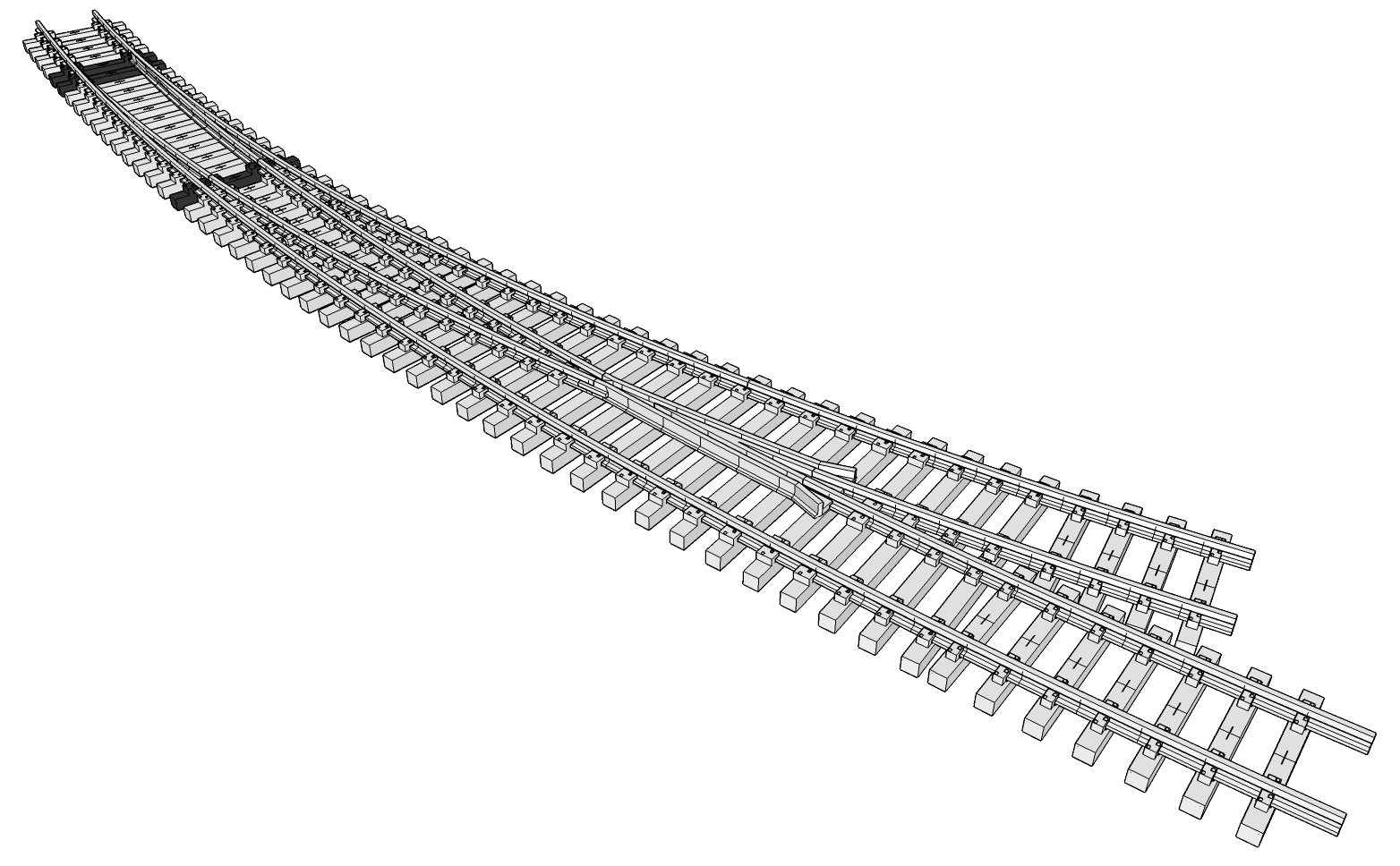
Welcome back to planet Unobtanium! If you thought finding Aristo-craft #6 or wye switches was difficult, or anything in stainless steel for that matter, good luck finding anything curved. As rare as they are on the prototype, it’s no wonder they’re nonexistent in garden scale. If you know of anyone who makes them, or made them, please leave a comment and let me know!
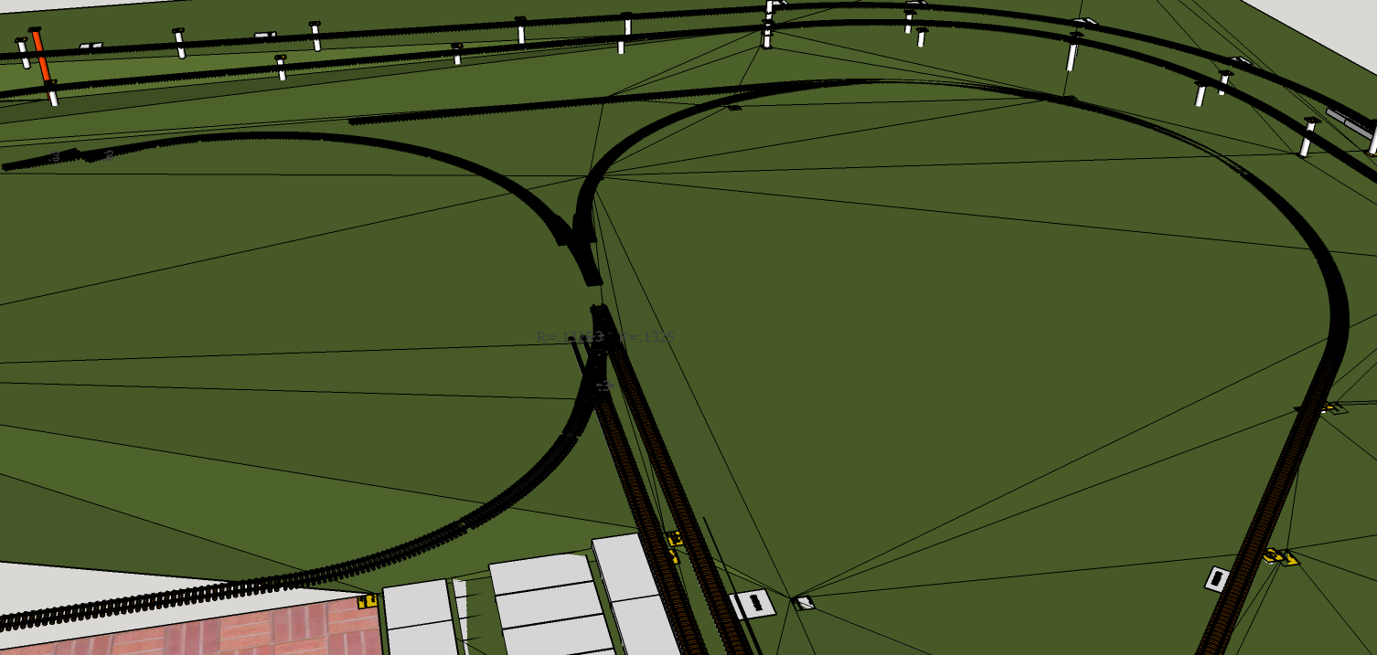
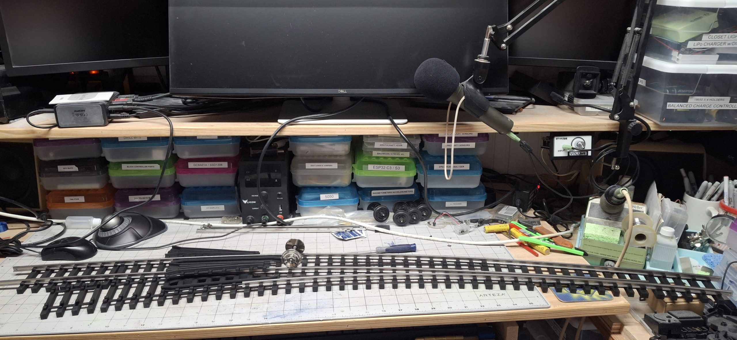
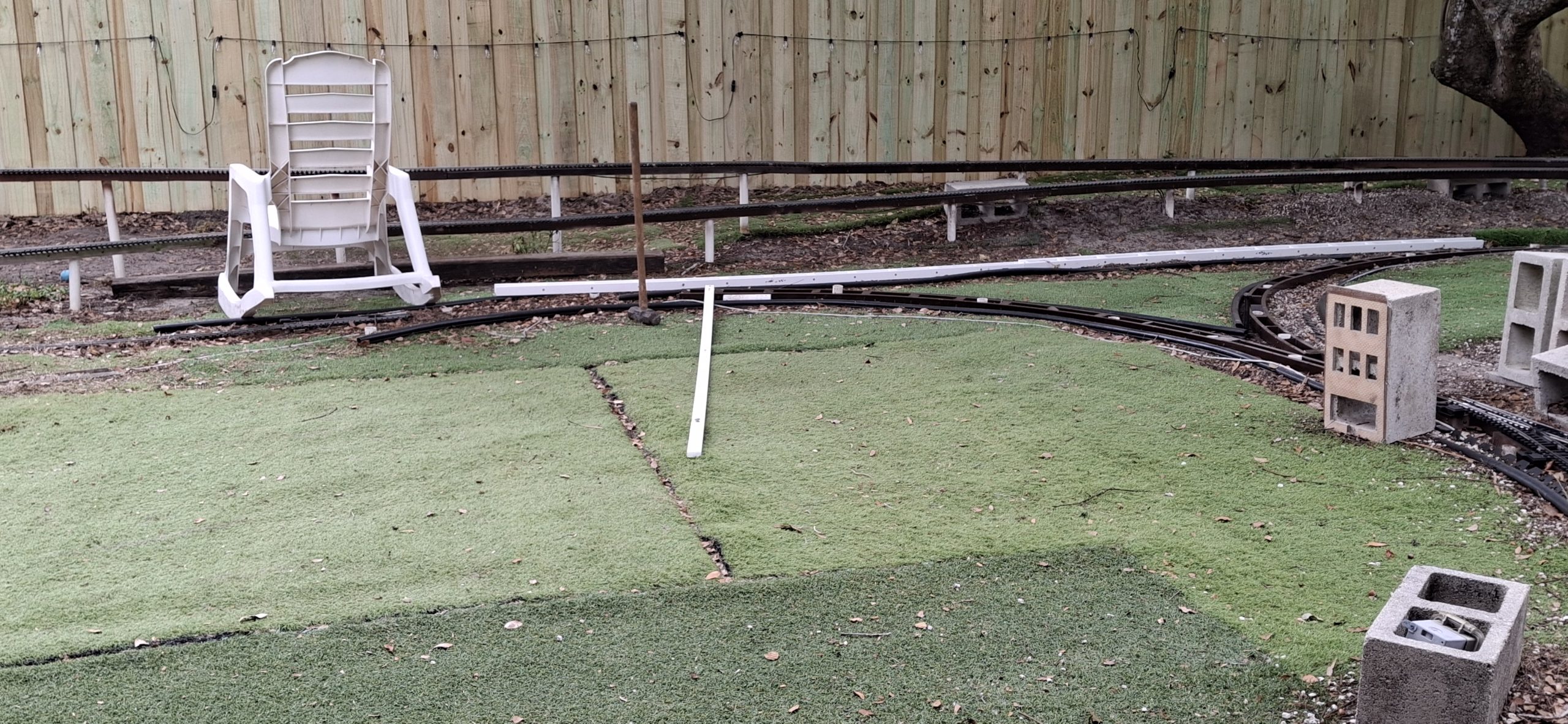
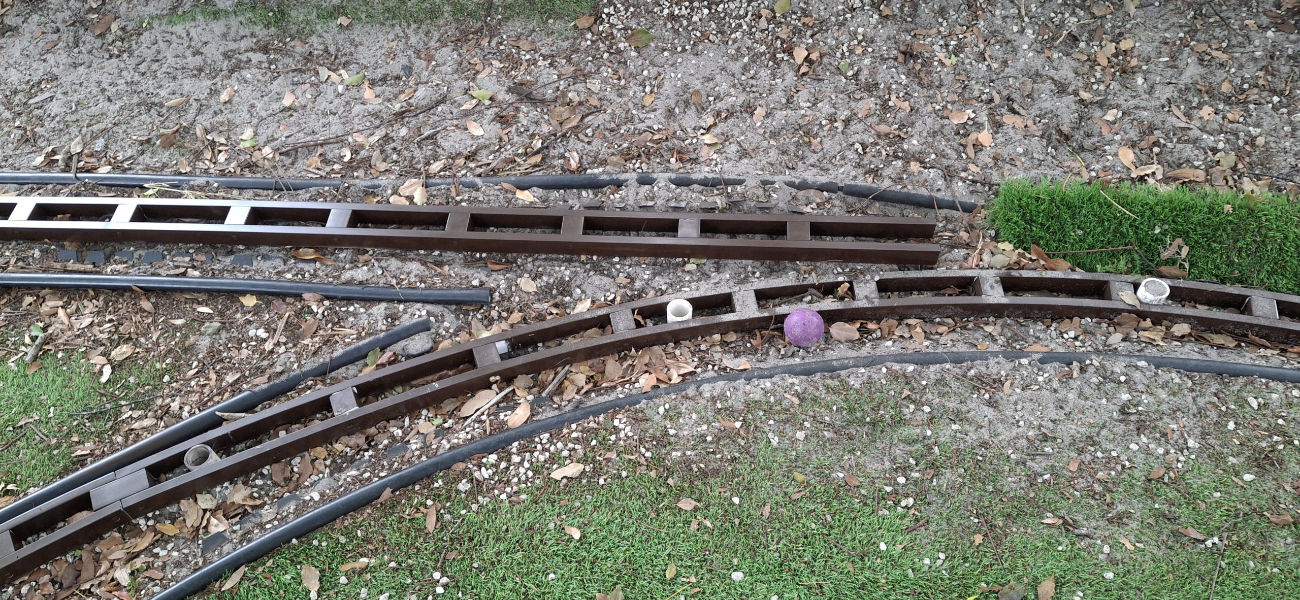
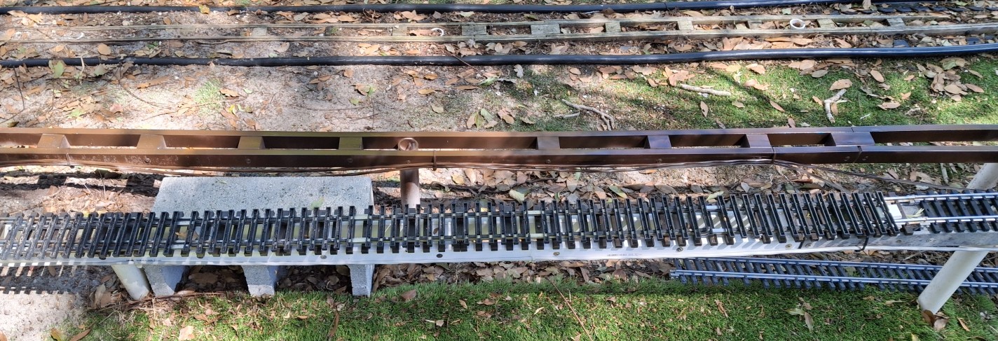
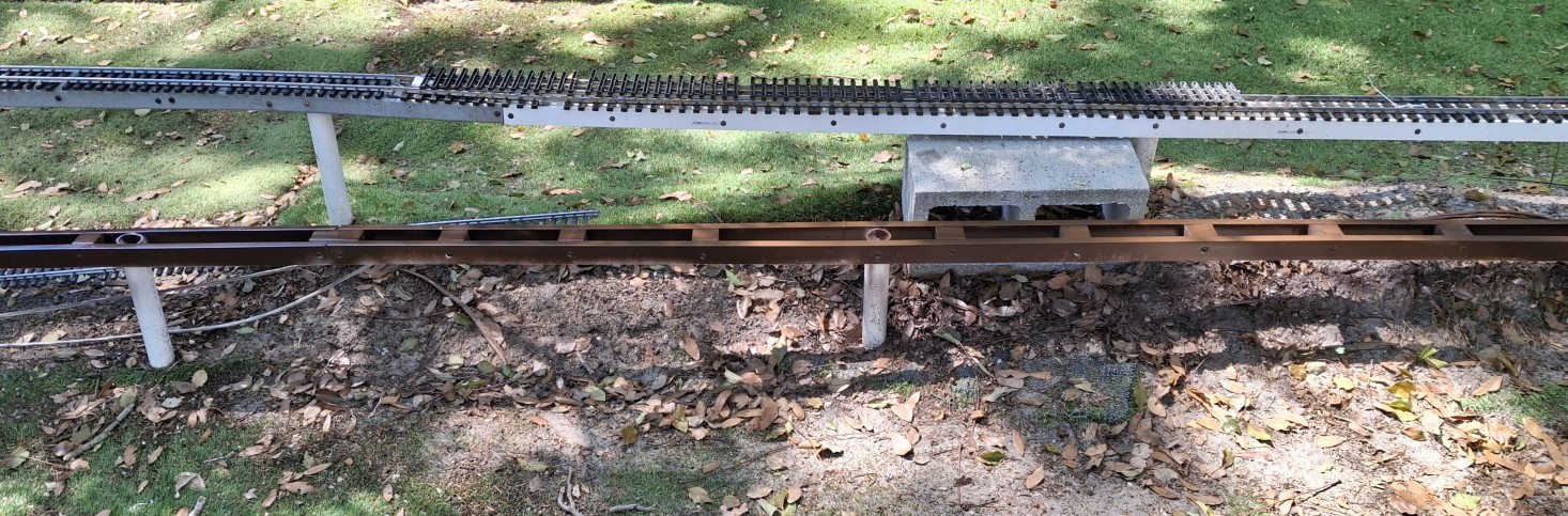
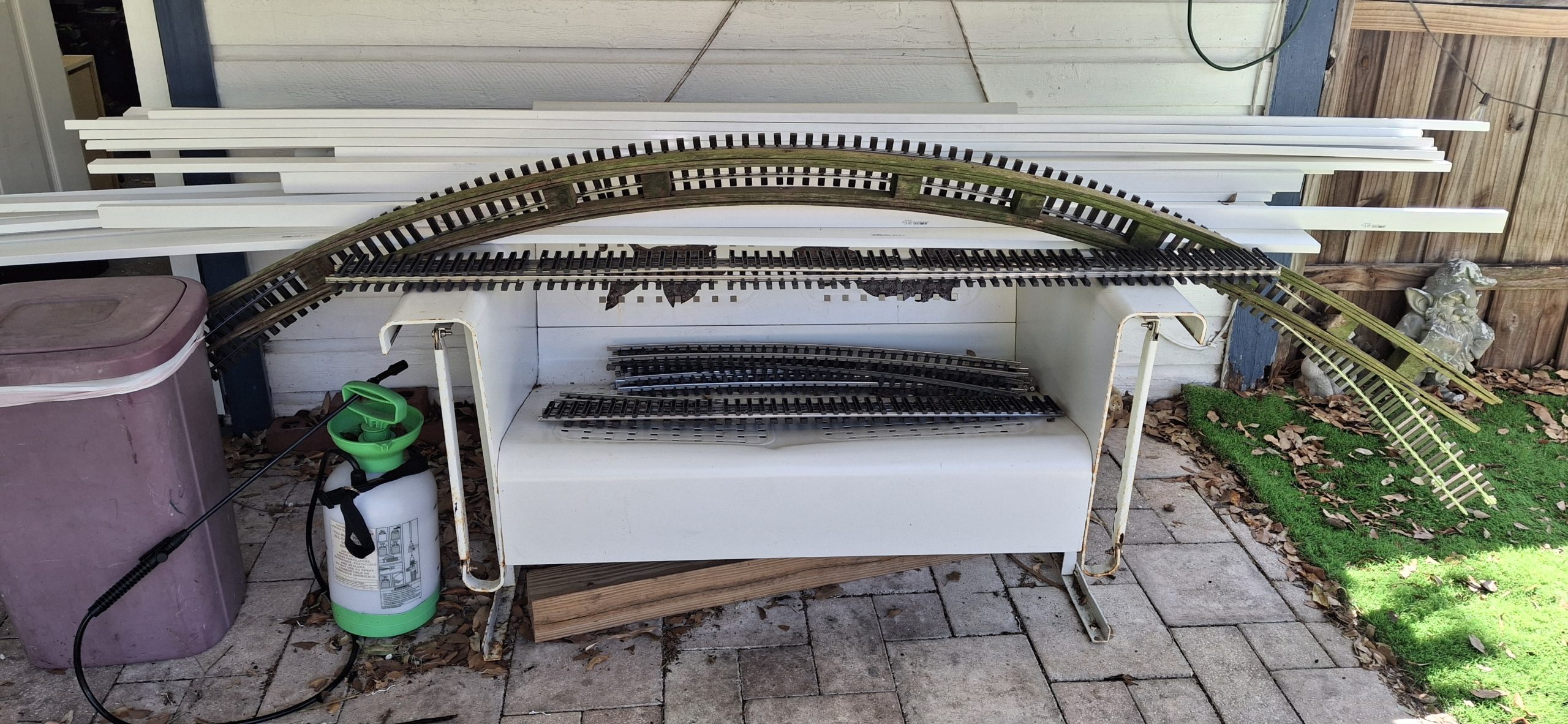
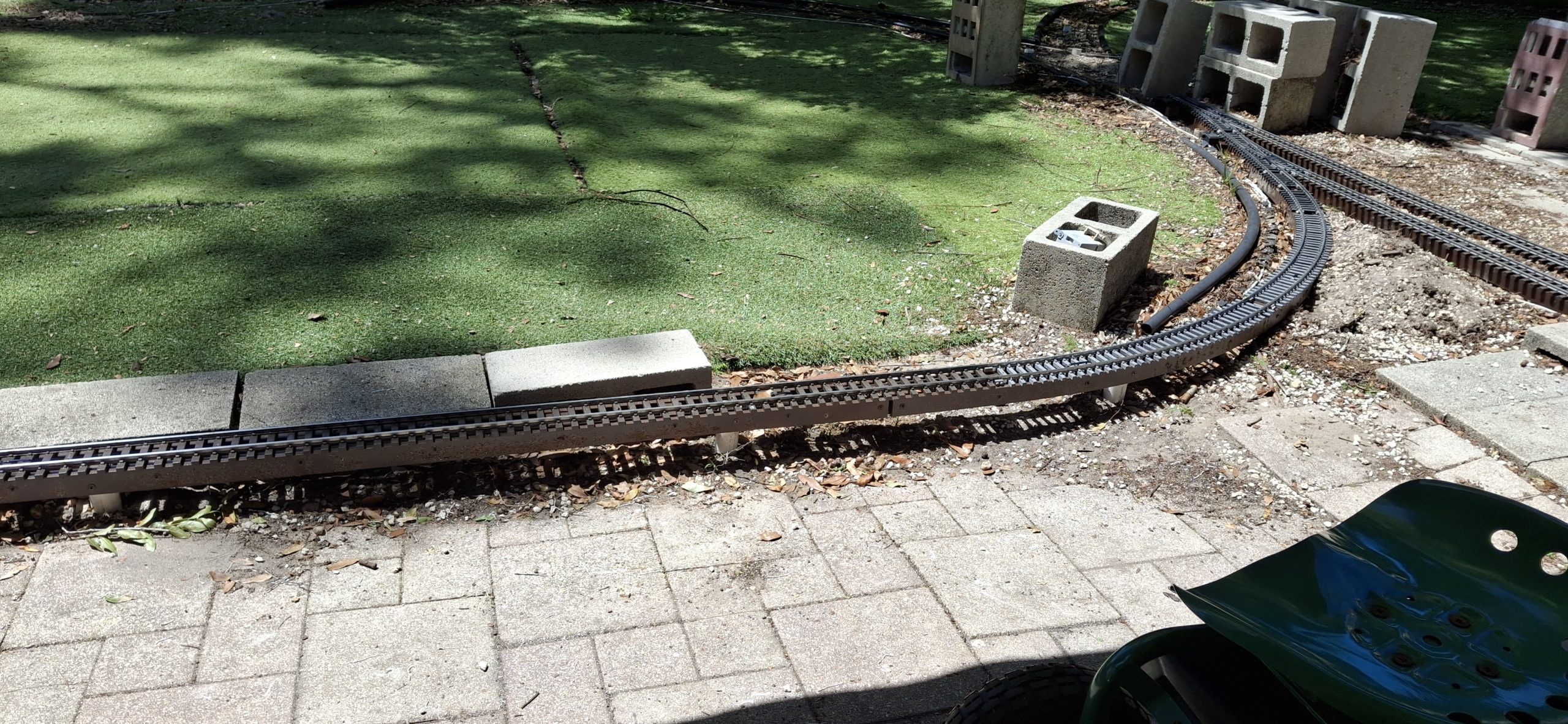
For the longest time I’ve struggled with how to “complete” the downtown wye. Due to space constraints, a standard switch won’t fit. We’ve designed ourselves into a corner, so to speak. In this case, a 14′ diameter semi-circle of track, and a need to escape it at the quarter circle mark to join with the diverging leg of the wye.
We “cheated” before by replacing one of the 14′ diameter sections of track with a 20′ diameter section, connected directly to the diverging route away from downtown. This left no way to enter the downtown leg of the wye from that direction. That leg was still accessible from the direction of the actual wye switch, but now nothing more than a dead end spur.
Necessity’s A Mother
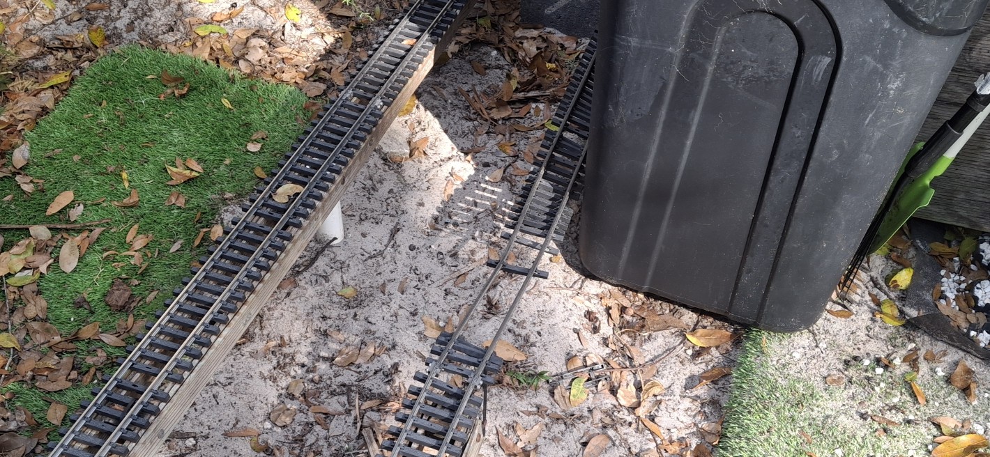
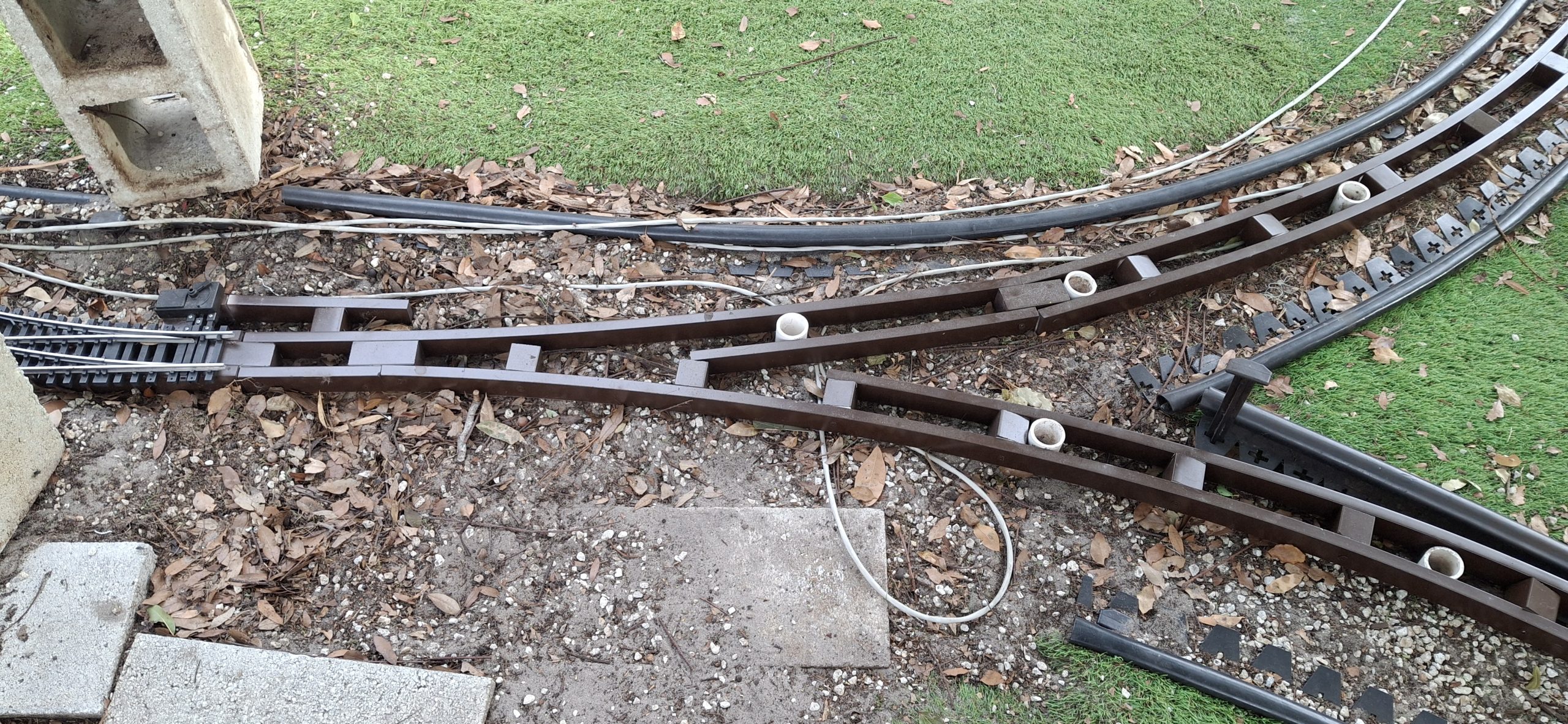
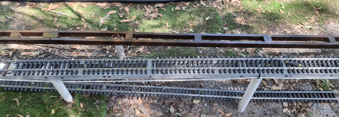
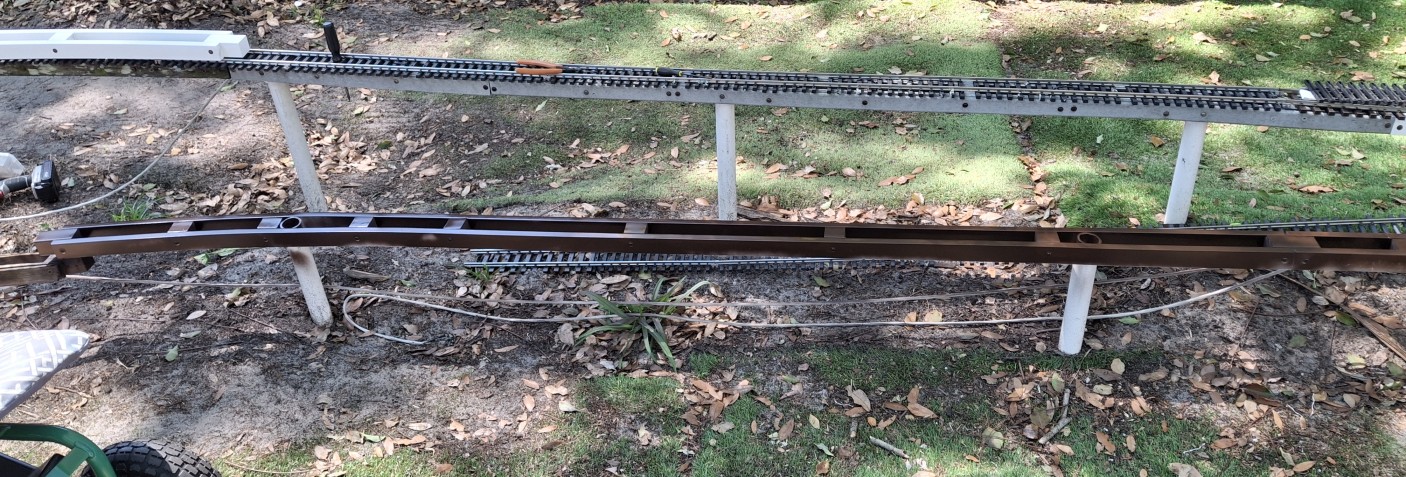
The wye switch was removed as well. The leg into downtown from the south has a wide radius switch, but that was also rearranged to better fit continuous operation. That entire section to the south leads to the lower loop around the deck. To avoid the need for a reverse loop controller, automatic or otherwise, the switches are placed “toe-to-toe” rather than “heel-to-heel”.
This one’s definitely going to need a picture (or three). I’m waving my hands over here trying to describe it and can already see the blank stares… We’ll get to that shortly. For now, let’s just say we side stepped this issue in favor of continuous running. Eventually we’ll need that auto-reverser, but that’s another project all by itself.
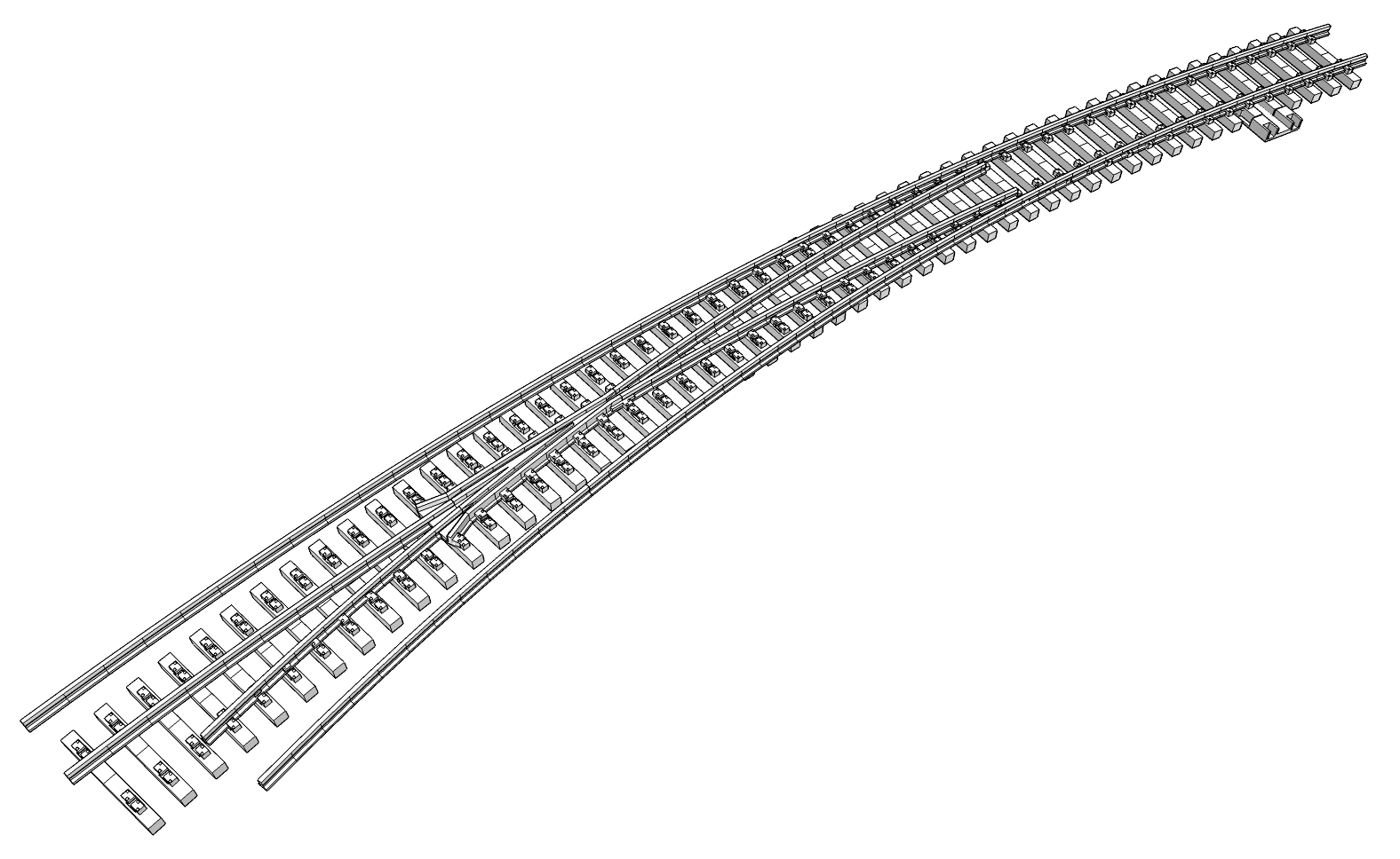
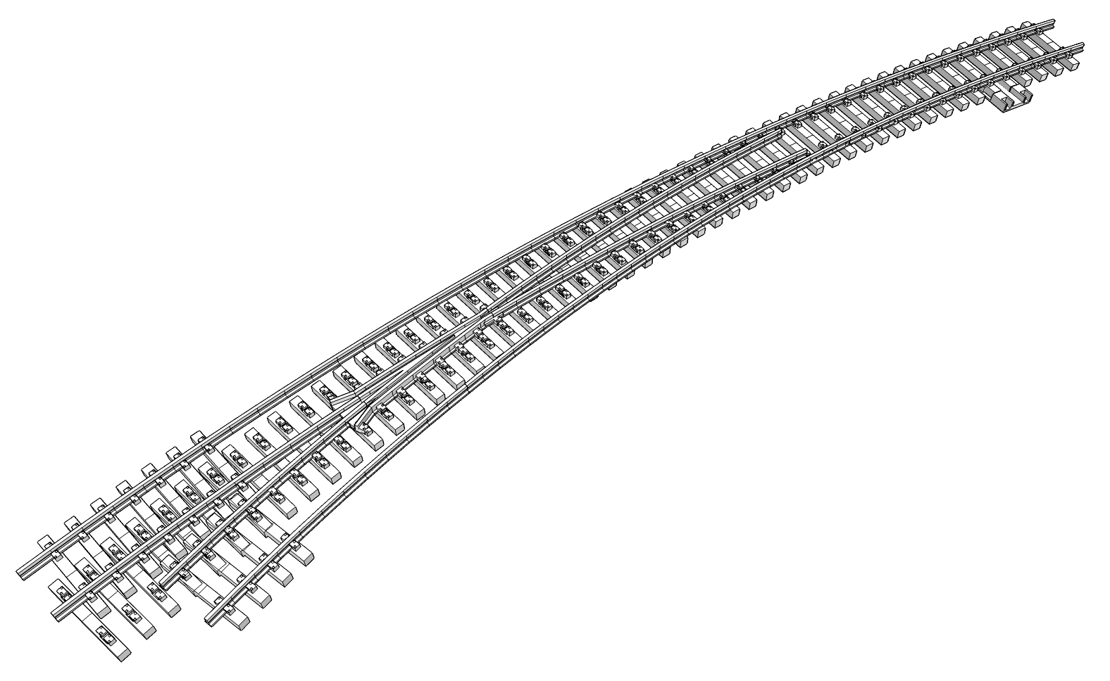
We’ve finally reached the point of needing that curved turnout. Which means it’s time to design one and start making it ourselves. To that end, I resurrected the homemade #5, an old tangent to 14′ diameter switch design I started drafting up ages ago. I shelved it when I realized I was in over my head, still a novice with the SketchUp software and 3D printing.
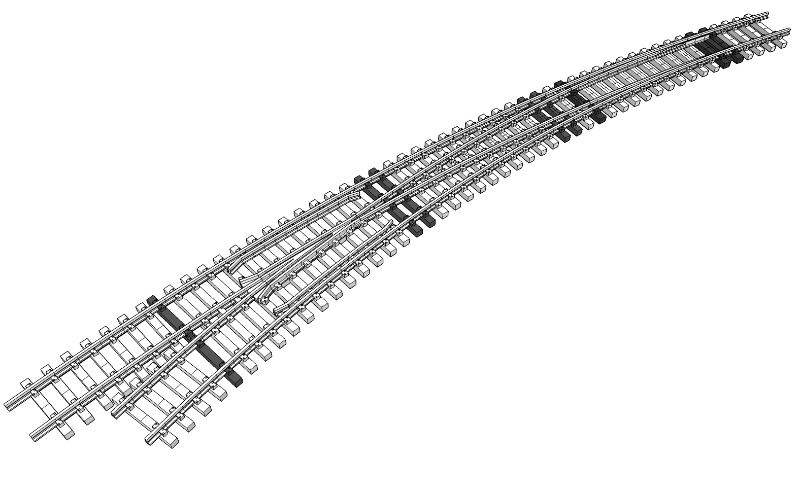
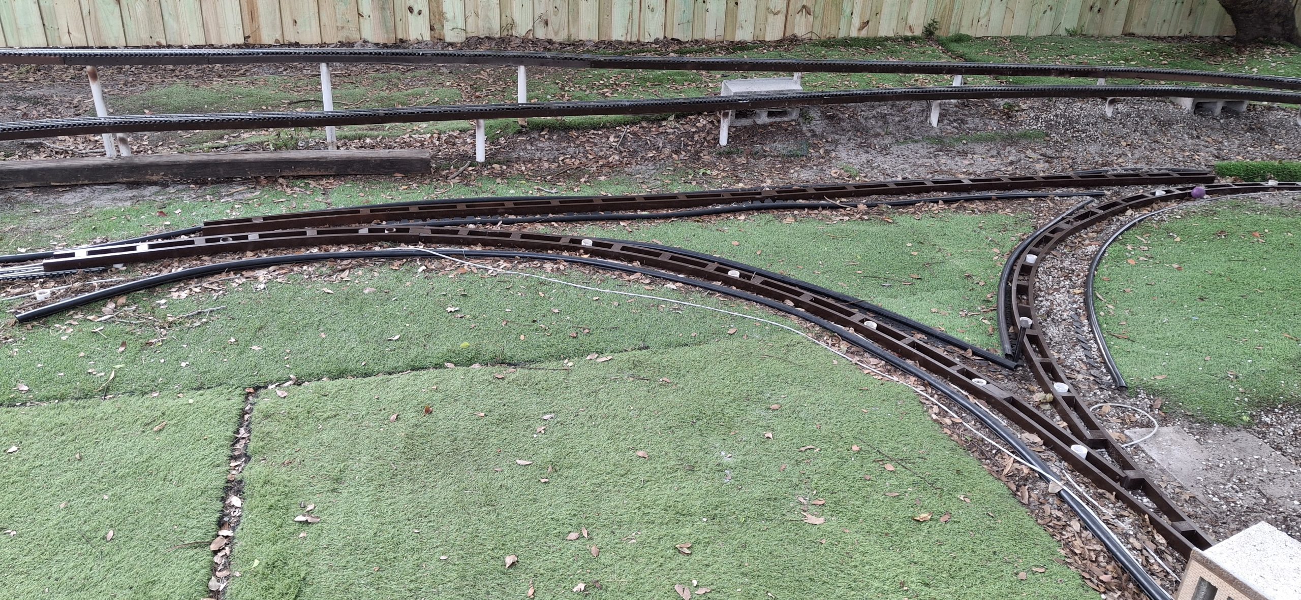
The Downtown Wye ArrangementWye South Leg Toe To Toe Switch Arrangement
A New Hope
I last touched that design in early March of 2020 and it shows! I’ve gained a lot of experience in those six years though. Now I’m putting it to the test on the homemade curved switch. All my time has been devoted to this new design, when I’m not working on replacing the rotted stringers that is, which means anytime during the week when I’m not working my day job.
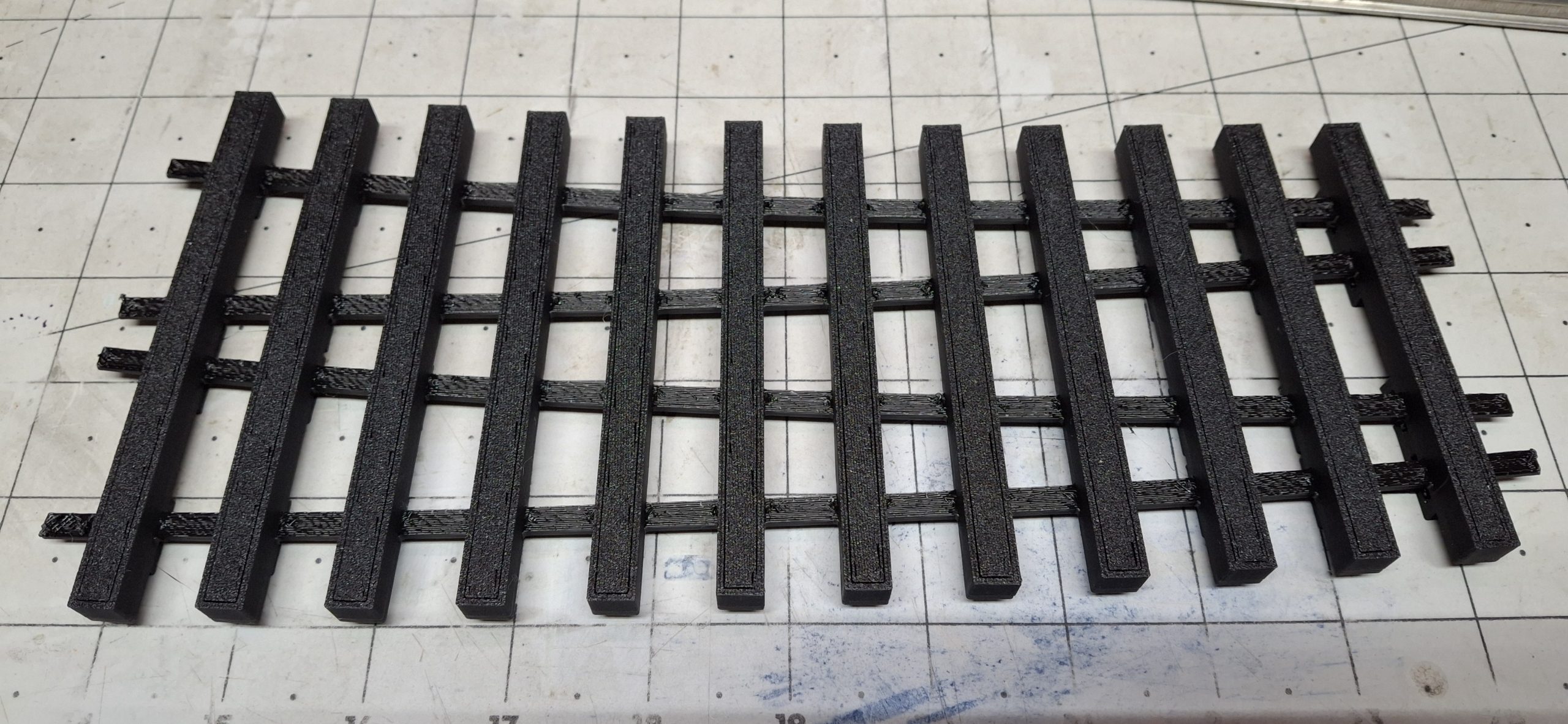
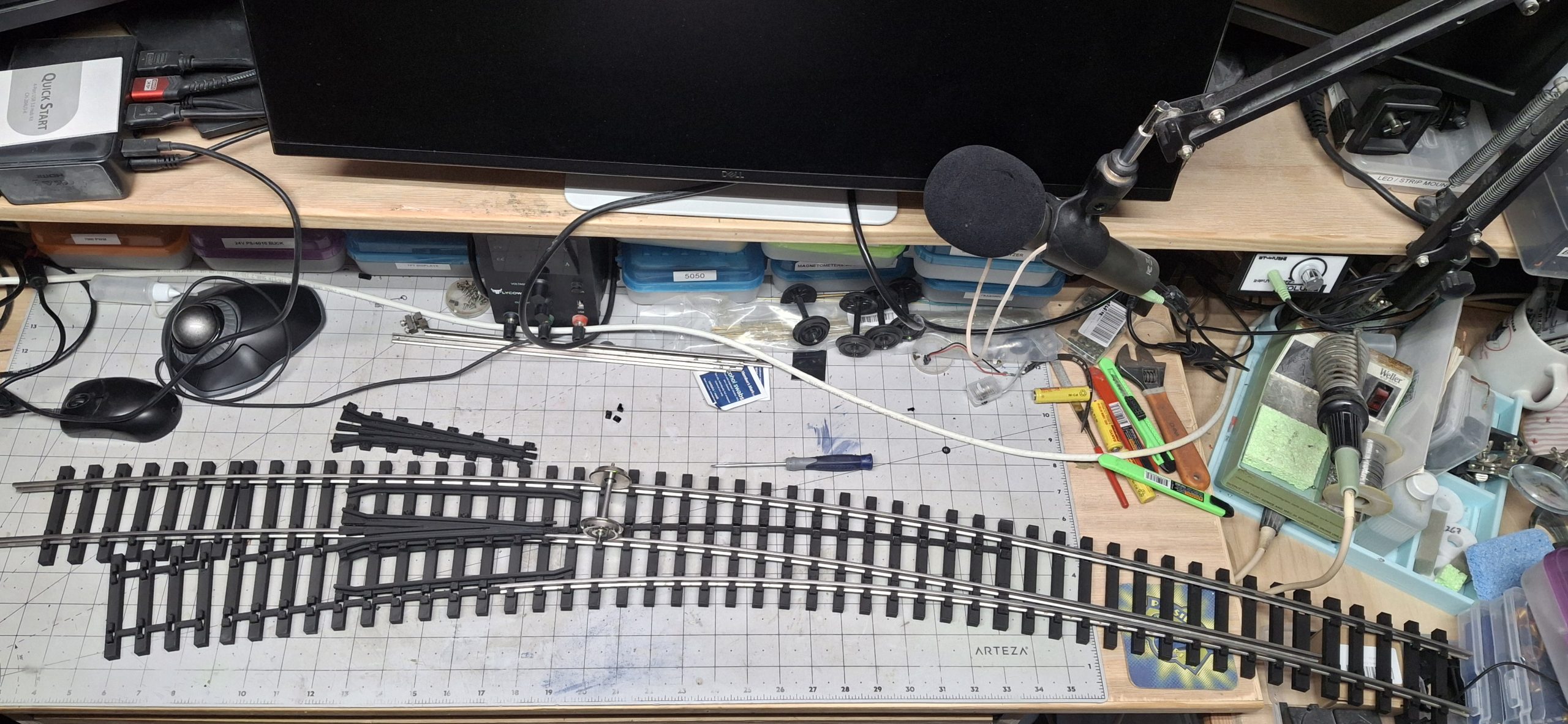
All that dedication paid off. In a little less than a week the preliminary design is complete and the prototype tie strips have all been 3D printed! Test fitting the tie strips for the heel and point rail ties suggests the fit is “a bit snug”. And by a bit snug, I mean I had to use the tack hammer to “tap” the inside 14′ diameter stock rail into position.
The remaining tie strips are printed and all the support material removed, all but those on the frog ties. Some background on the design of these tie strips. Each tie is connected to the next by a strip of material in order to keep them spaced apart and in the proper position relative to their placement along the switch. Hence the name “tie strips”. But I’m getting ahead of myself again.
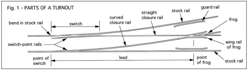
Parts Of A Turnout
Technical Difficulties
Ann tells me this is probably too technical for folks that haven’t looked at turnout (switch) design before. Too many unfamiliar terms and a bunch of hand waving around them without any kind of visual reference to help understand what I’m talking about. Let’s address that. The term “switch” refers to just a portion of the actual “turnout”, but the names are commonly used interchangeably.
Hopefully the diagram will be helpful. When discussing the stock rails, it means the two outside rails. The point rails are actually the switch part of the turnout, meaning they switch the route through the turnout, normal (usually the straight path), and reversed or diverging (usually the curved path). The closure rails are a continuation of the point rails, past the hinge point, as they’re closing in on the crossing (frog) of the diverging rails.
The frog has wing rails and guard rails help to guide the wheels through the frog. The idea is the wheel tread slowly leaves the wing rail as it also slowly begins to ride on the frog, smoothly transitioning from one to the other, starting around the point of the frog. That’s probably enough about switch design and far more than most folks would care to know about it. Again, hope this helps clear up any confusion.
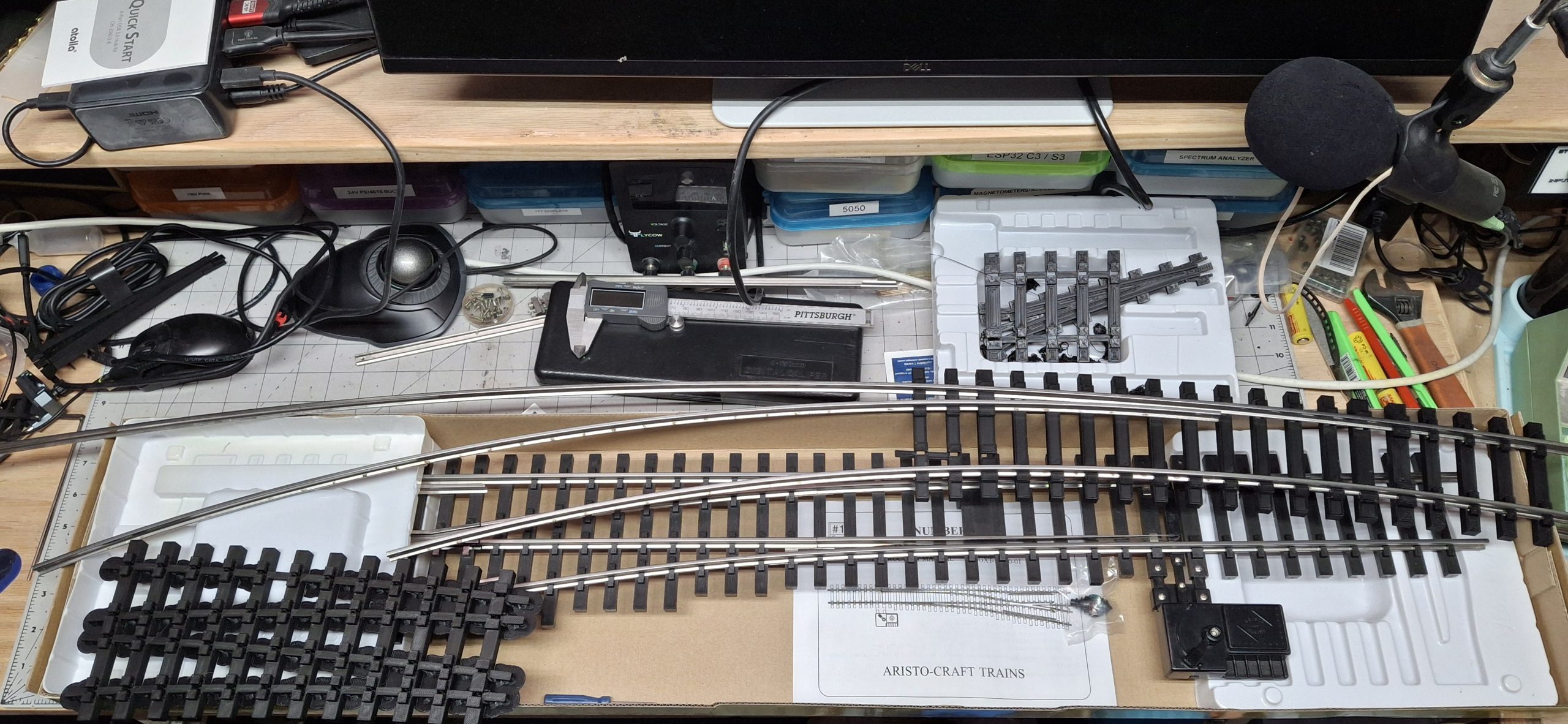
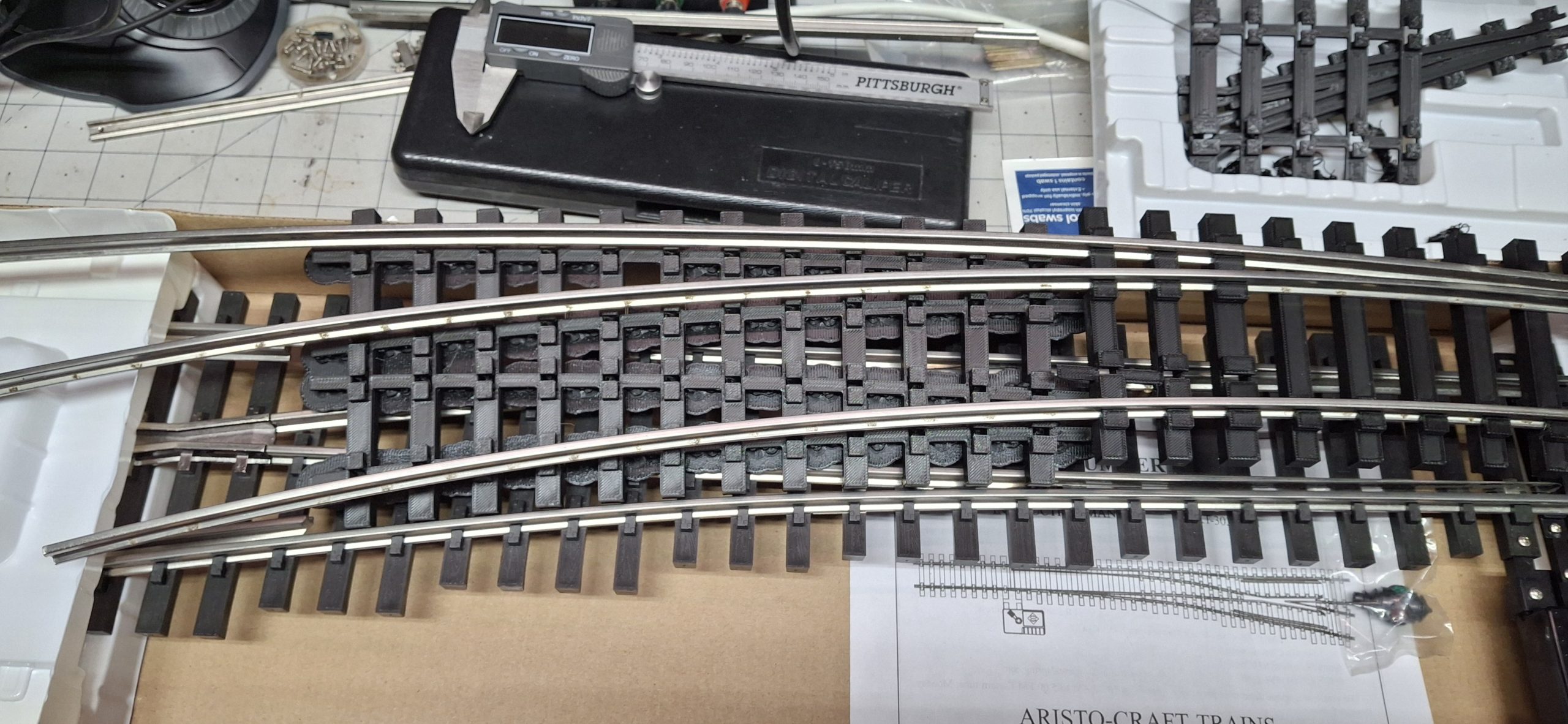
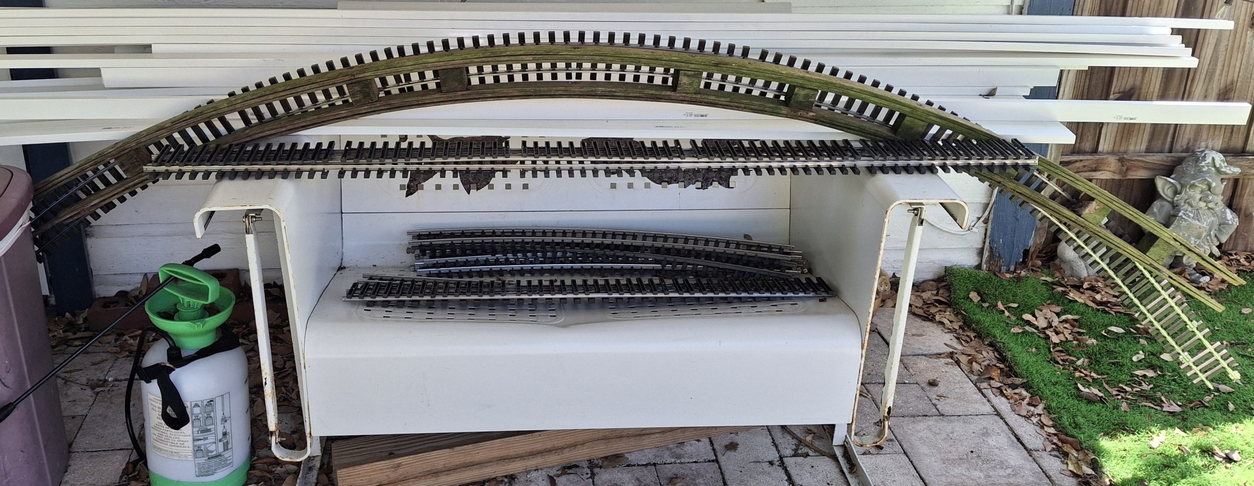
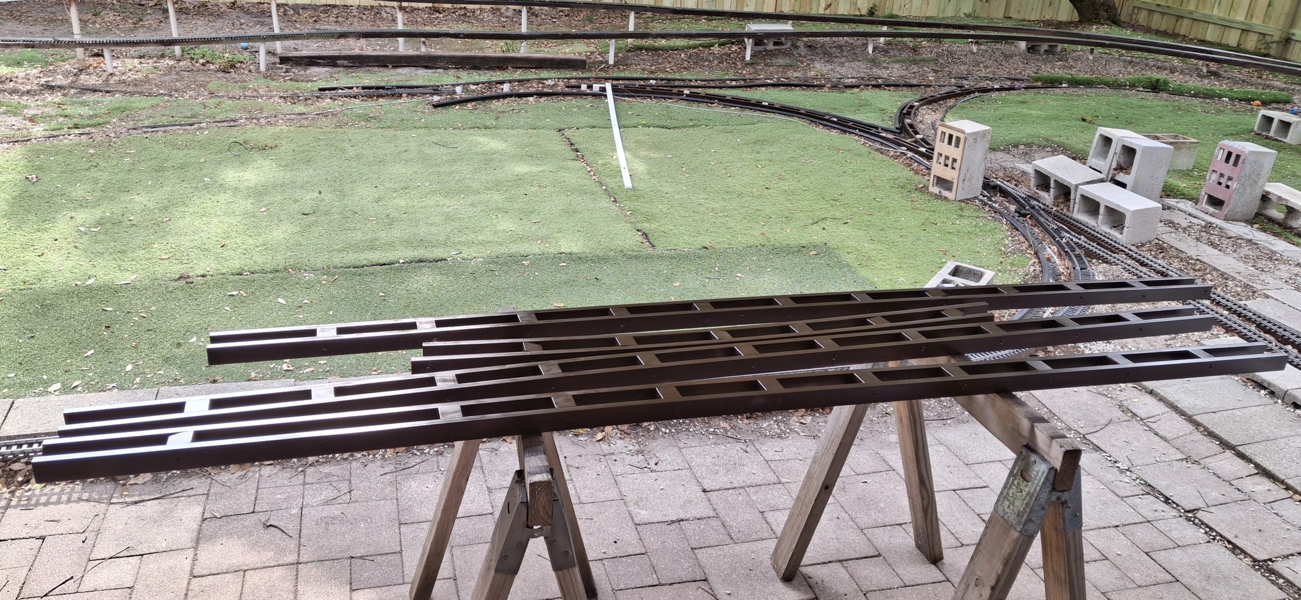
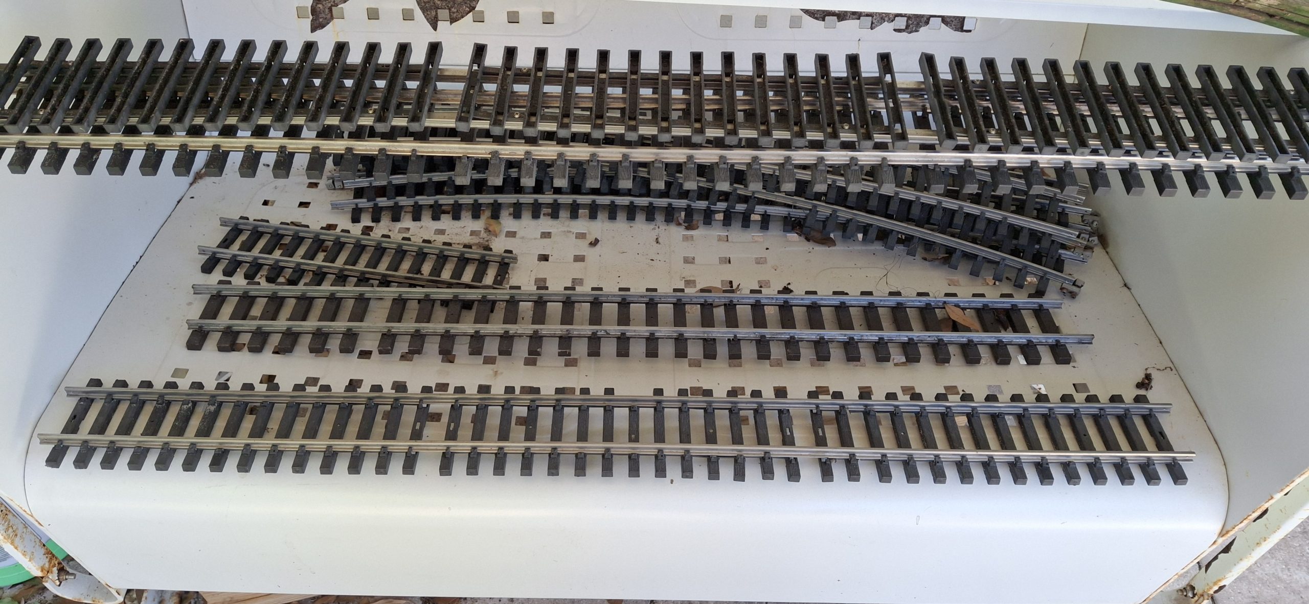
Size Comparison Between An Aristo-Craft #6 Switch To Our Homemade Curved SwitchClosure Rails Tie Strip With Supports Still Attached Closure Rails Tie Strip With Supports Still Attached (Bottom)Closure Rails Tie Strip With Supports Removed
Design Considerations
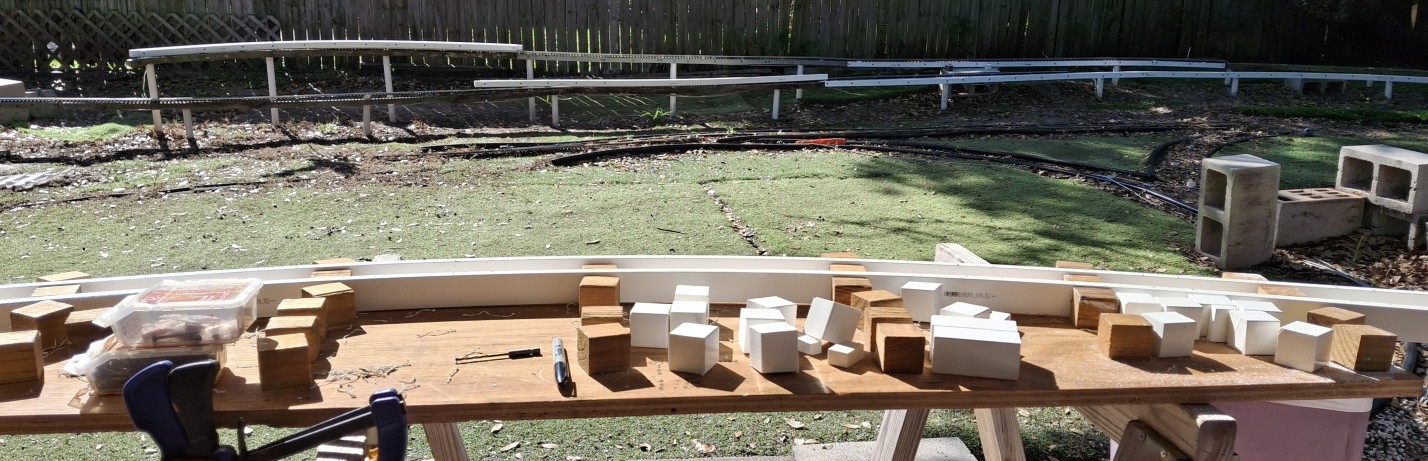
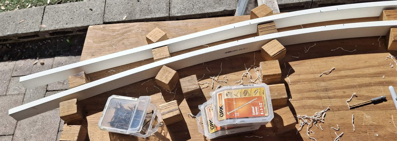
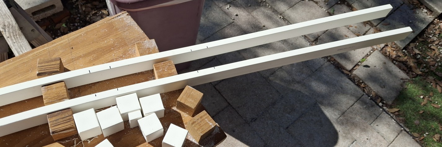
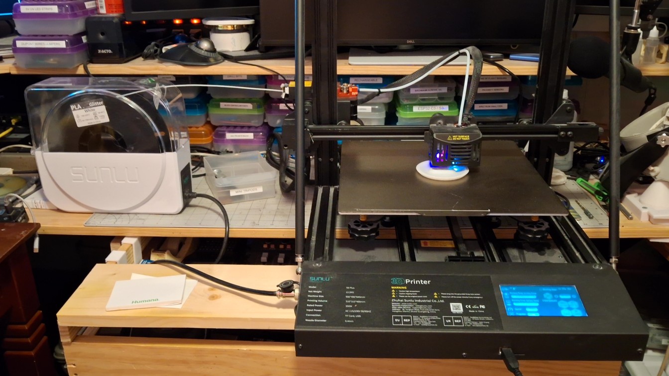
The tie strips are designed to be around 12″ at the longest, mainly due to 3D printer build volume constraints. The new 3D printer, an AnyCubic Kobra S1 Max, arrived not even two weeks ago and has a build volume of 350mm x 350mm x 350mm (13.77″ x 13.77″ x 13.77″). Needless to say I’ve been anxious to put it through its paces and see what it can do.
I’ve already encountered the “out of filament” event. An event that revealed what a total piece of crap the “old new” Sunlu 3D printer is when it comes to filament management. It certainly detects when it’s out of filament. It complains about it and asks for the filament to be replaced, but then loses its mind after that, requiring a power off reset to recover from it!
The AnyCubic? It functions the way the Sunlu should have. When it detects it’s out of filament, it homes the print head, remembering where it left off. Then it prompts to confirm refilling the slot in ACE cabinet. Once it detects the new filament is inserted it primes the system and awaits the request to resume printing, which it does, right where it left off! It’s a dream come true.
A Poor Assumption
It’s not all rainbows and unicorns though. As I mentioned, the fit is a bit snug. The ties are fragile, cracking and splitting along the layer lines when pressing them onto the rails. But by far the biggest drawback of the initial design is all the support material. It takes about half an hour to remove all the support material from each tie strip, using needle nose pliers no less!
Let me step back and describe the original design approach before we go much further. The design is “copied” from the original Aristo-craft switch ties. The thought is it worked for them for years, so it should provides clues where to start, and should be a good jumping off point for our design. Well, that was a poor assumption, at least for the ties themselves.
There are other limitations to the Aristo-craft switch design, but we’ll get to those shortly. Their tie design was meant to address injection molding and manufacturing constraints that we don’t have. We do have constraints, just not the same as those. Our constraints are related to 3D printing and the materials available that can survive the heat.
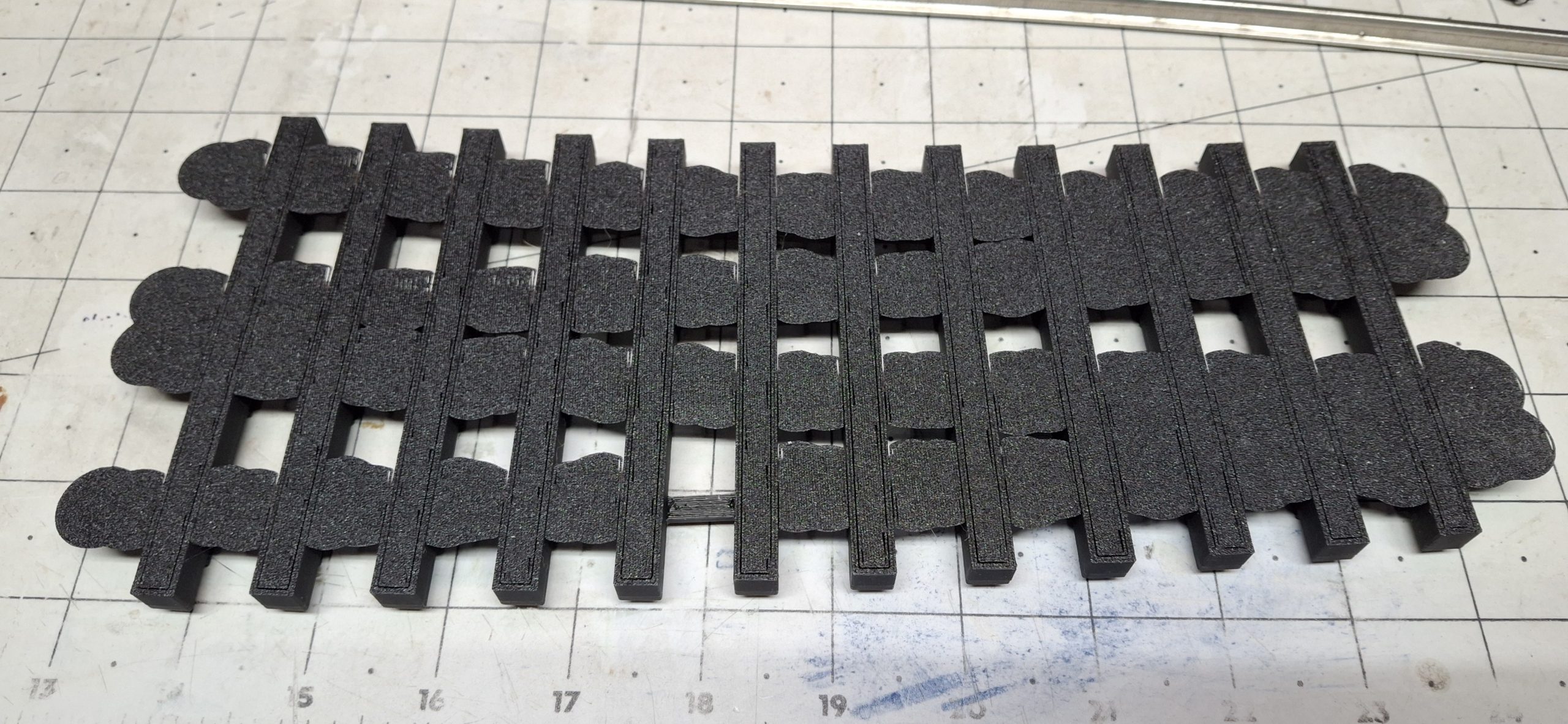
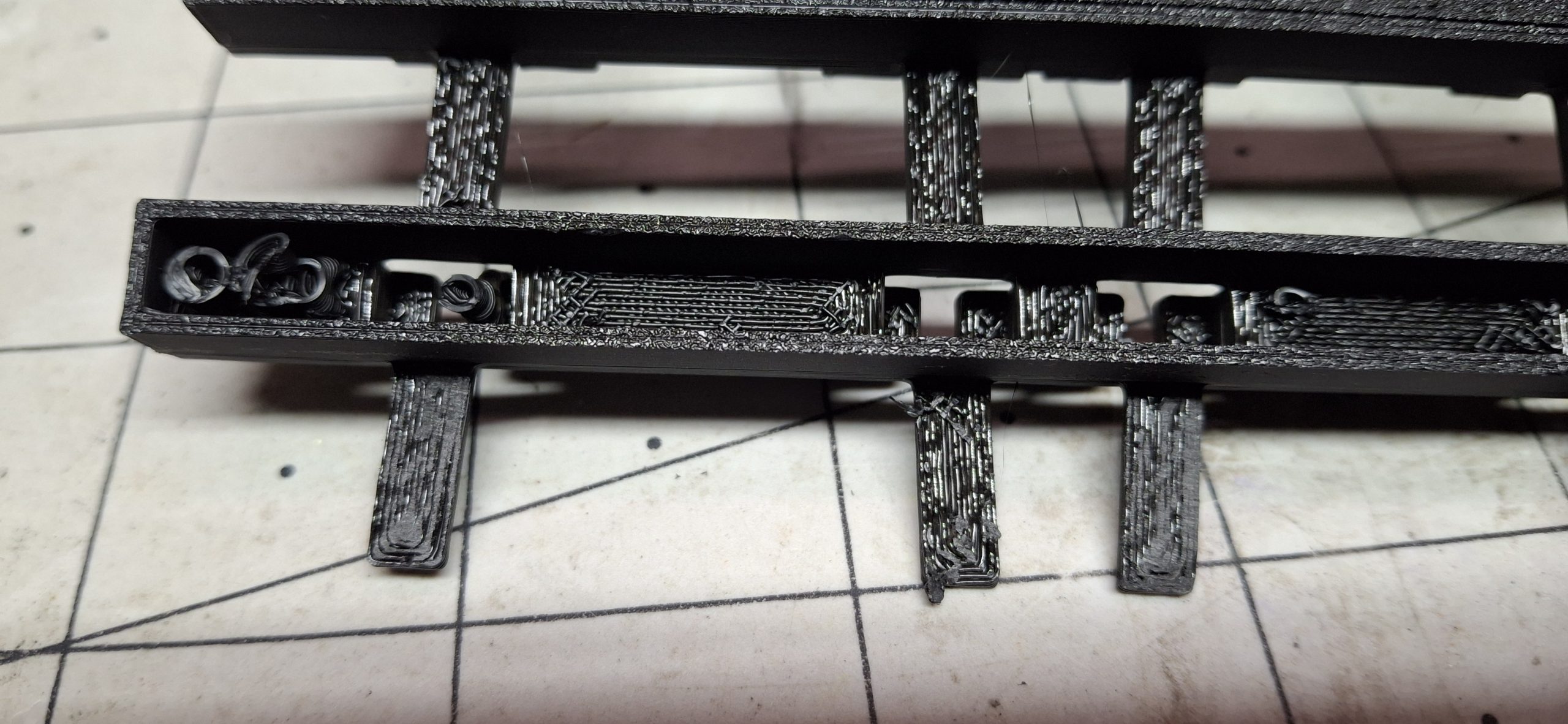
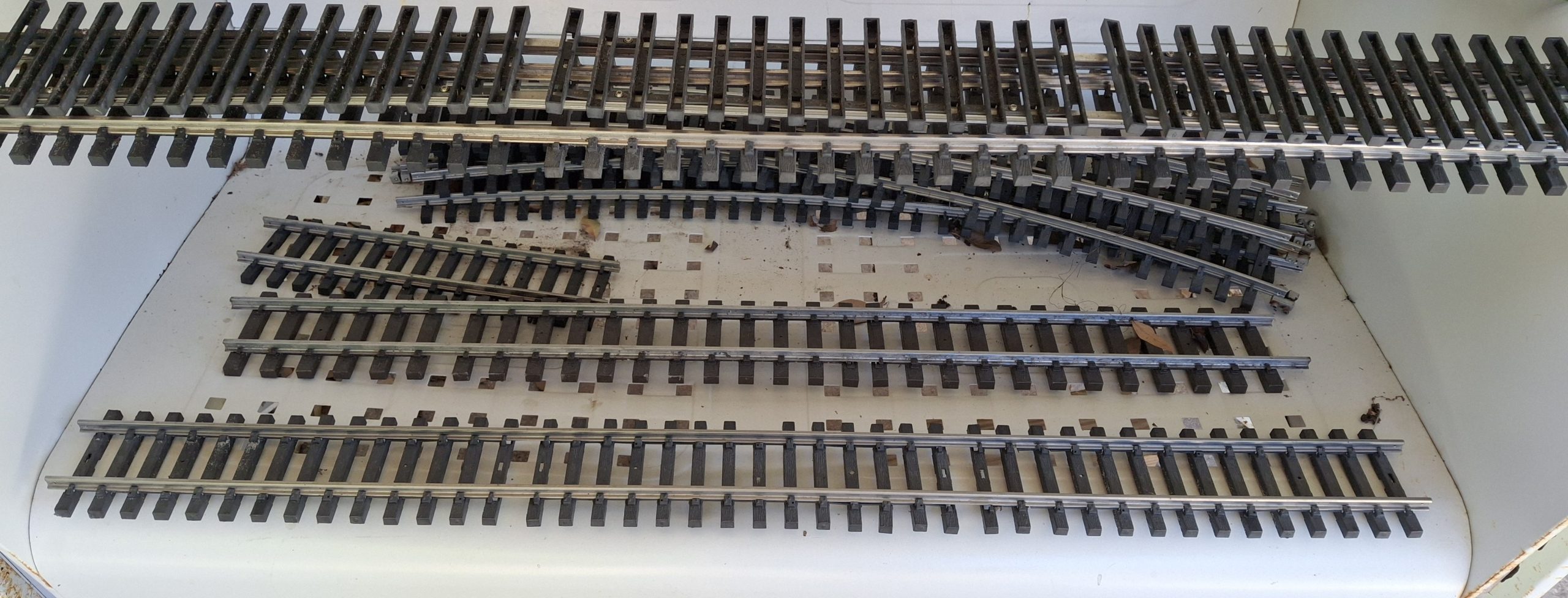
Closure Rails Tie Strip With Some Supports RemovedClosure Rails Tie Strip Detail Of Hollow Tie Supports Partially Removed Closure Rails Tie Strip One Hollow Tie And Rail Foot Clamp Supports Totally RemovedClosure Rails Tie Strip All Hollow Ties And Rail Foot Clamp Supports Totally Removed
Differing Design Constraints
The Aristo-craft design uses “hollow” ties with thin walls and openings on the tops of the ties where the rail “foot clamps” live, presumably to conserve the amount of material injected per part into the molds and facilitate the release of the parts from the molds. Parts in this case refers to the tie strips, not just single ties.
The Aristo-craft injection molds themselves provide the “overhang” support for the underside of the top of the tie. We don’t have that luxury when 3D printing. Any overhang of more than a 50° angle from vertical will cause issues. With nothing to support the molten plastic, it droops and deforms. Those familiar with 3D printing will know it as “bridging”.
Successive layers above the area of bridging depend on those previous layers for support, now missing and drooping because of lack of support beneath them. Again, those familiar with 3D printing know that supports are “waste” material. They get printed along with the desired part, but are only there to bridge the overhangs and support the layers above.
Refining The Design
After printing is complete, the supports must be removed, usually tossed in the trash. Wasteful, but necessary when the desire is to print as one piece, not many that need joined together in some fashion. For tie strips, we could certainly print a dozen or more separate ties, then print two strips of rail foot holds, one for each rail, and glue them all together.
I’ve not tried that approach, but have to think it would take just as long to glue a tie strip together as it does to remove all that wasted support material inside the hollow ties. A better approach would be to just redesign the ties to be “solid”, that is to say a defined number of walls in thickness with a certain percentage of infill inside them.
The ties don’t need to be hollow to begin with. That was an injection molding constraint. For not much more material than would have gone into printing the supports then thrown away, what used to be waste material is now incorporated into the tie itself, producing a much stronger tie in the process. If it’s going to get used anyway, may as well add it to the part!
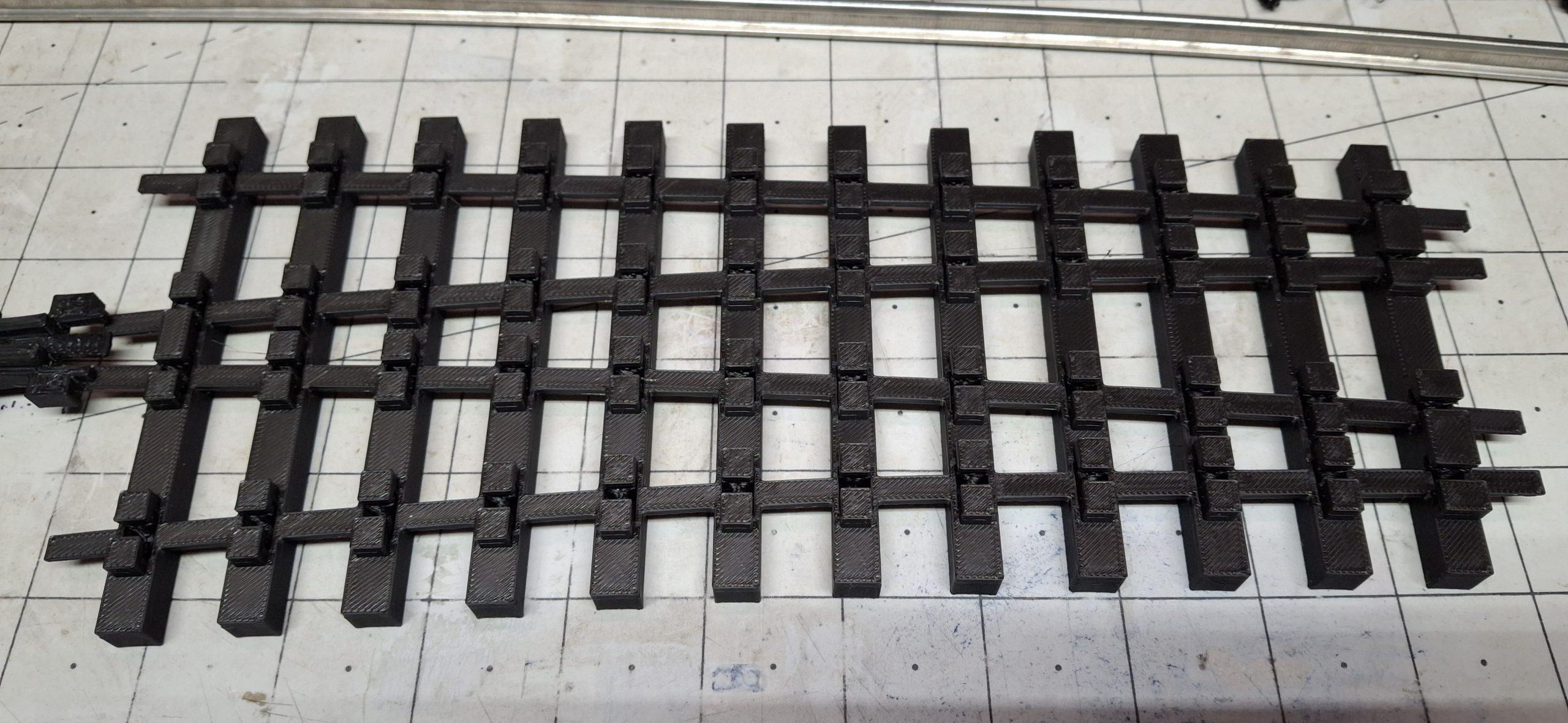
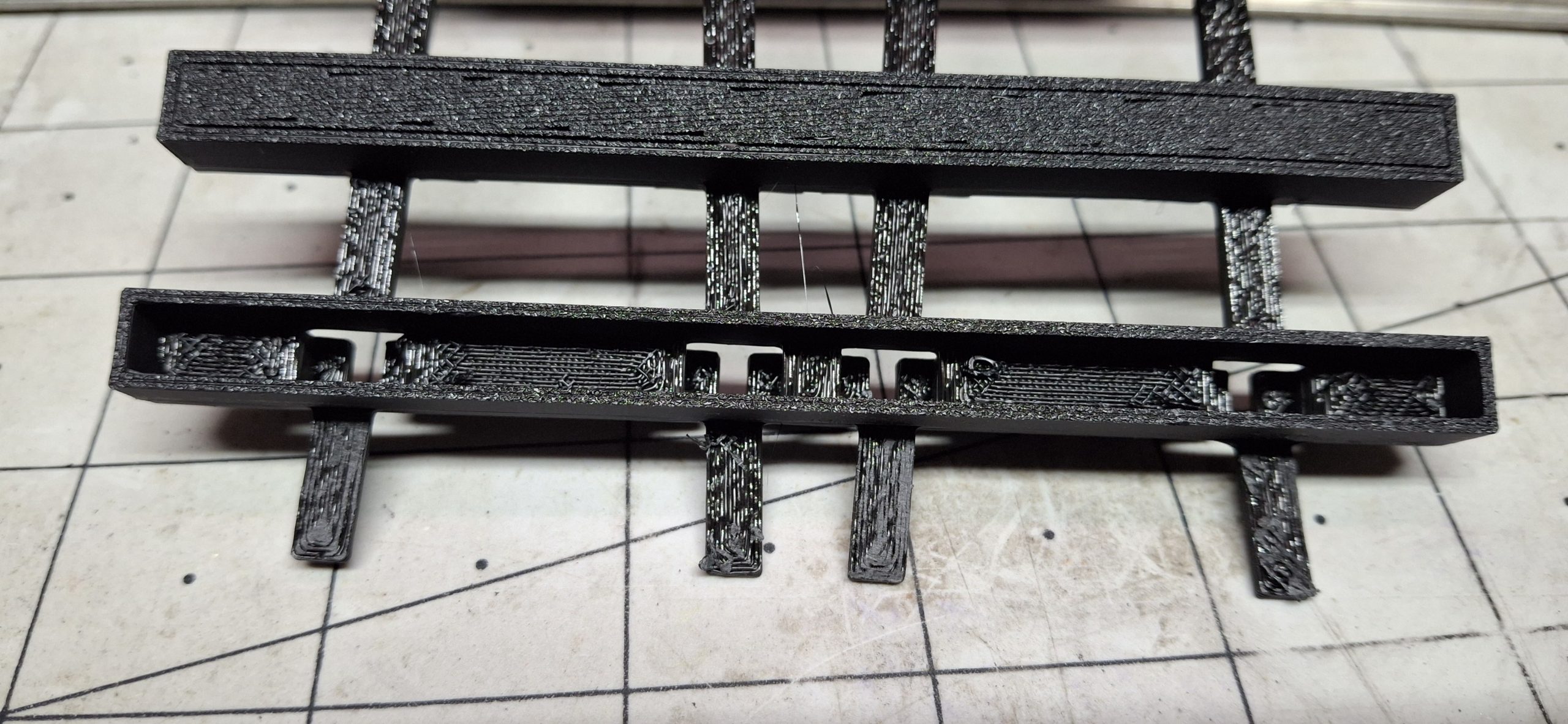
All Tie Strips Plus Frog And Integral Guard Rails On Frog Tie StripComing Together With All Tie Strips And Frog For 20' Diameter Route
Further Refinements
I kicked off printing the frog tie strip before getting out in the Barkyard, working on more stringer replacements. It’s more than a five hour print, which gives me plenty of time to refine the design for solid ties and put together a couple more PVC stringers. The tie strips for the diverging routes all use a single tie model, so updating the design fixes those eleven ties all at once. The rest of them? Not so much…
The print of the frog tie strip had long since finished by the time I knocked off for the day from replacing stringers in the Barkyard. I hadn’t planned on being out there all day, but managed to correctly re-construct the two wye legs that had been plagued by my previous misguided assumption about the wye switch. With the needed curved switch about to become a reality, it made sense to correct the mistakes of the past.
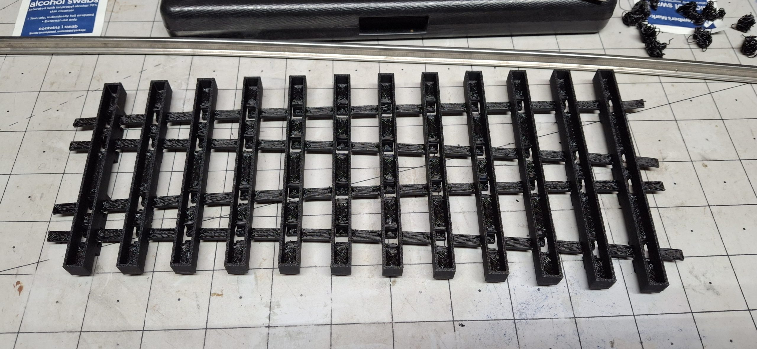
I removed frog tie strip from the build plate flex sheet and kicked off printing those diverging route tie strips. When they were done printing, I started the process of removing all the supports. This time it’s limited to just the connecting strips, which easily break off by hand, and the rail foot clamps. Those still require the needle nose pliers, popping them out from the top into the hollow area beneath. Quick and easy!
I tried removing the supports from the frog tie strip, this time concentrating on removal of just the supports for the foot clamps. The rest of the support material in the hollow of the tie can just stay there. It’s not visible, so why bother? I stopped short of removing them all though.
Further Refinement Considerations
Those diverging route tie strips are much stronger with infill and the ease of removing the supports is another vote in favor of this redesign. Another consideration for refinement is the tight fit of the foot clamps on the rails. I had already eased the fit by ten to twenty thousandths of an inch (¼mm – ½mm) in places where the rail angle compared to tie is large.
I forgot to add the supports for the foot clamps for the redesigned print and accidentally discovered they’re unnecessary! It’s a Bob Ross “Happy Accident” moment. So now we’re down to just the strap supports, which are easily removed in a minute or two. That’s a helluvan improvement over the half an hour for the previous designs.
Let’s rewind to the original design idea for this curved switch to better understand that last statement about rail angles and foot clamp clearances. Even with standard tangent to diverging curve switch designs, on the diverging route the rails fall at an angle to the ties. Eventually toward the end of the diverging routes, the ties resume their normal perpendicular orientation to the rails when they no longer interfere with each other.
Now consider this is a curved switch and regardless of which route is taken, we’ll call them them normal and diverging, since tangent doesn’t really seem to fit, both the normal and diverging rails will always be at an angle to the ties, save for those final diverging route ties. Given both routes are curved, one way to minimize that angle is to arrange the ties to the average curvature.
Tie Layout And Spacing Using Average (17' Diameter) CurvatureTie Layout And Spacing Using Average (17' Diameter) Curvature With Toe Ties AddedFinal Tie Layout And Spacing Based On Average (17' Diameter) Curvature
Initial Design Constraints
In our case, midway between the 14′ and 20′ diameters is 17′. Starting with the original tie design from way back, they are arranged every half degree for the full 22.5° curvature of an entire 20′ section. I made this a constraint to avoid the tragic outcome from my previous mistaken assumption that the Aristo-craft wye switch was a full 20′ diameter section. Ours is an entire 20′ diameter section long, coming in at around 4′.
When a full 22.5° 14′ diameter section is placed over the 20′ section, it’s only long enough to meet where the frog will sit! Anything less than a full 22.5° section of 20′ diameter track would be less than a complete switch. I arbitrarily added an additional 7.5° to the 14′ diameter route to ensure the ties from sectional track segments won’t interfere with each other.
What can I say? A hold over from my HO days where the #4 switches need a 1/3 18″ radius section for the switch to replace a single 18″ radius 30° curve section. Those legs of the wye already use flexible track segments bent to fit properly. Worst case is an extra 7.5° needs removed to fit with the new curved switch in place.
Additional Design Refinement
Getting back to the design decision to use a 17′ diameter tie layout, each tie needs to be adjusted because of this decision, more so than if it were a tangent / diverging route switch. Both routes need to be adjusted, not just the diverging route. By adjusted, I mean the length of the tie and the position of the foot clamps based on rail position as well as interference fitment.
That’s where the 10 to 20 thousandths figure comes from. Each of those 48 ties needs careful consideration, from centering the foot clamps over the rail foot, to sighting down the length of the rail from the inside to verify clearances from the tip of the foot clamp to the web of the rail. It’s like using X-ray vision to eliminate any interference between them.
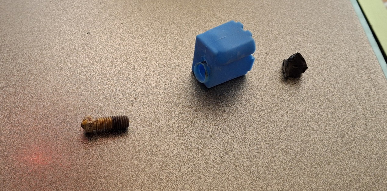
One other outcome of running out of filament is the brittle nature of the replacement filament. Don’t even look at those foot clamps wrong or they snap right off!. Finding out why this filament was so inexpensive. Definitely not a bargain. Never buying that stuff again. I’m guessing what I’d been printing with before was PLA+ and this latest stuff is just plain PLA. Dunno. It’s just plain crap for sure.
Zooming In Using "XRay Vision" To Look Inside The 14' Diameter Stock Rail For Interference
Real World Considerations
The brittle nature of the filament coupled with a lack of complete support removal is a sure way to snap it right off when attempting to test fit rail. So one more refinement will be to back off the foot clamps another 10 thousandths as well as raise them all by 10 thousandths. It’s also a vote to just reprint those other ties strips using the design refinements.
But that’s not as easy as changing one model to fix all of them like it was with the diverging route ties. Every one of those remaining switch ties is unique. Most have two additional rail foot clamps beyond the original two the model they’re based on came with. The exceptions are the approach ties to the point rails and the ties under the point rails. just sixteen of them out of the 48 switch ties.
I’m going to cut this one short for now. If I somehow manage to make substantial progress tonight, then I’ll come back and update this post. Otherwise, stayed tuned for Part II. There’s plenty more to be done to make this an operational switch, but so far there aren’t any show stoppers that would interfere with that goal.
Question? Concerns? Leave A Comment!
If you’re interested in obtaining the STL files to print your own curved switch, leave us a comment and we’ll be happy to email them to you. Also, if you have any other questions or concerns, please feel free to comment on this post. In any case, you’ll need to create a user account to do so. We don’t use any personal information for marketing or to spam you (see our privacy policy). You’ll receive a verification email. Reply to the link provided to verify your email address. It’s all automatic. No waiting on moderator approval! No spamming your inbox with useless advertisements and “Special Offers”. None of that nonsense.
Welcome back! We’re still welcoming Spring with new PVC stringers. If you missed our first post, you may want to start there first. This is a continuation of what we started there. Except now it’s well beyond the first day of Spring, nearly the end of April at this point, and we’re still working on replacing stringers! This post covers another three weekends of effort.
This is taking much longer than expected, but continued improvement each weekend brings us closer to our goal of running trains. We left off with all the elevated sections painted and installed. In addition, the downtown mainline, station siding, and long siding are installed. Those took longer because those stretches are on the ground and more rotted stringers needed dug out first.
The track is installed as well, with the one exception of the stretch where the bridges will go. For now it’s just a straight elevated section waiting for track and bridges. Originally the thought was the approaches would be of trestle construction, but now I’m leaning toward laced steel girder supports and plate girder bridges. That can wait until later. We can run trains without any of it.
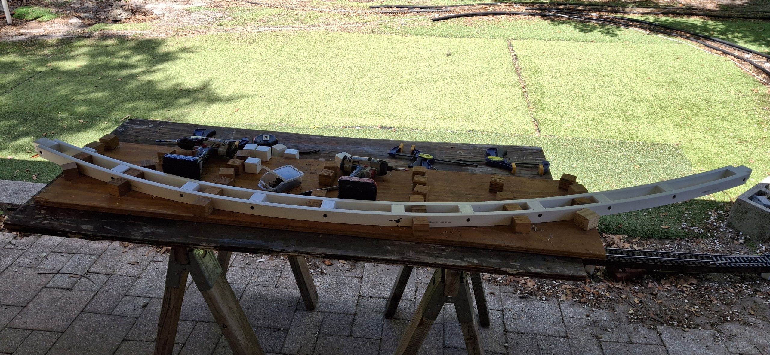
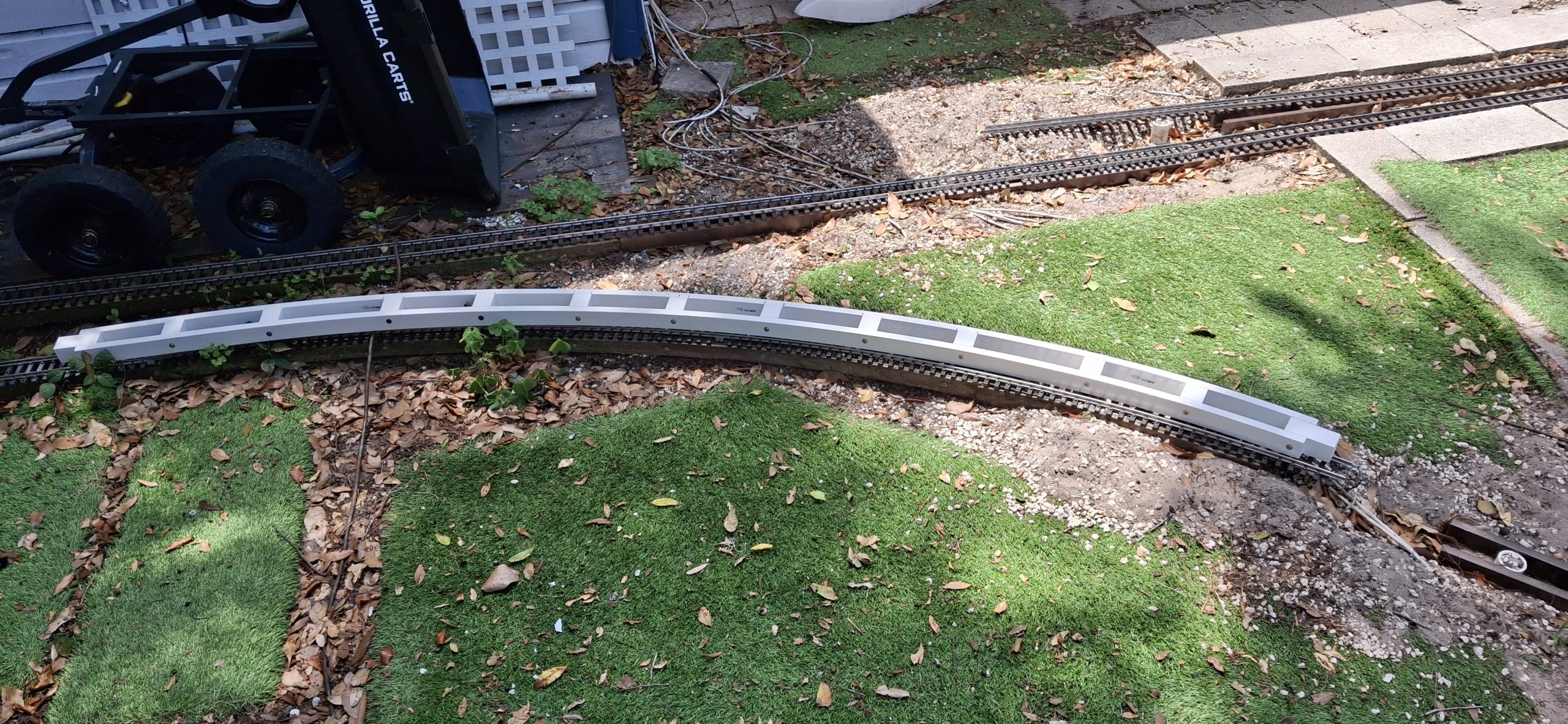
Making Another 14' Diameter StringerAnother 20' Diameter Stringer Ready For Paint And Placement Downtown Loop Main Street CrossingDowntown Loop Replacement Stringers
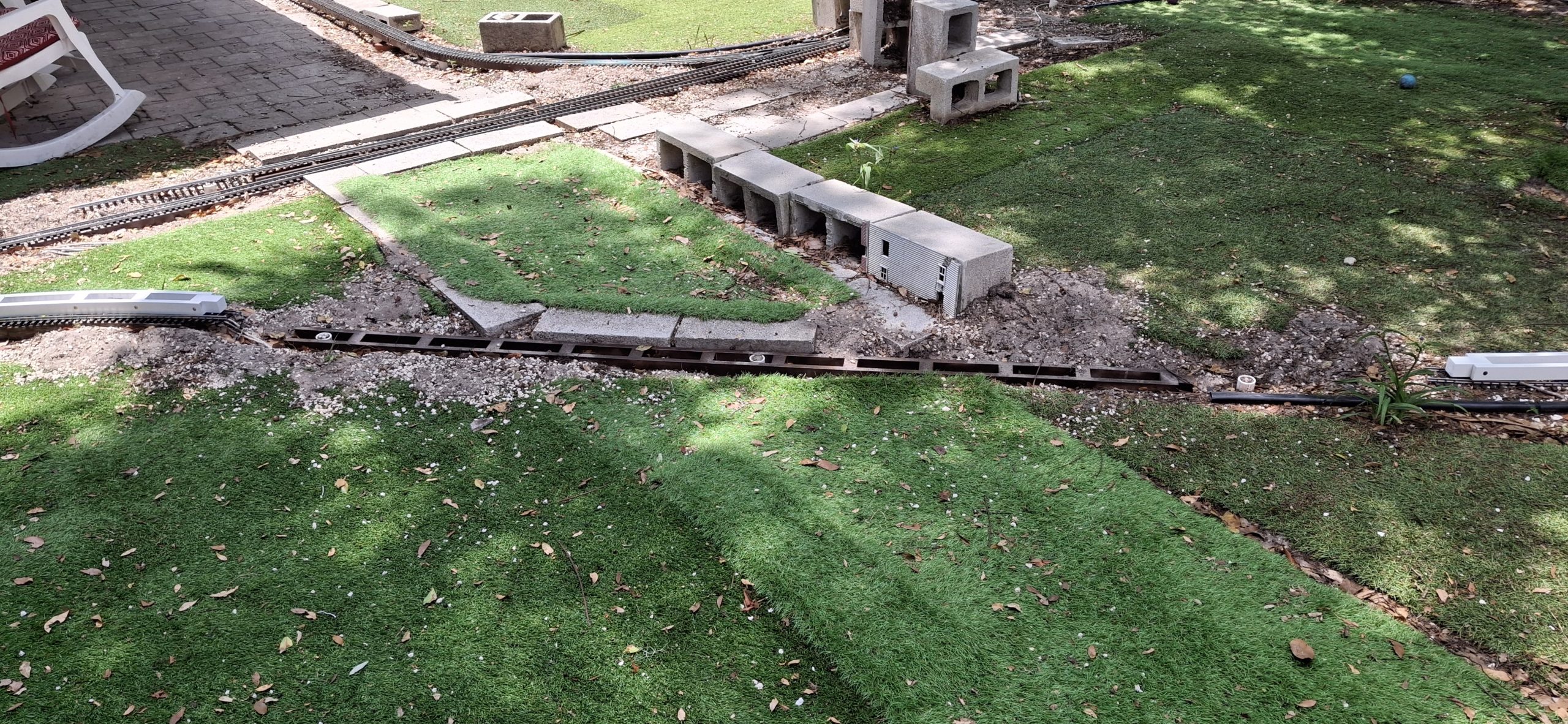
Fixing The Wye
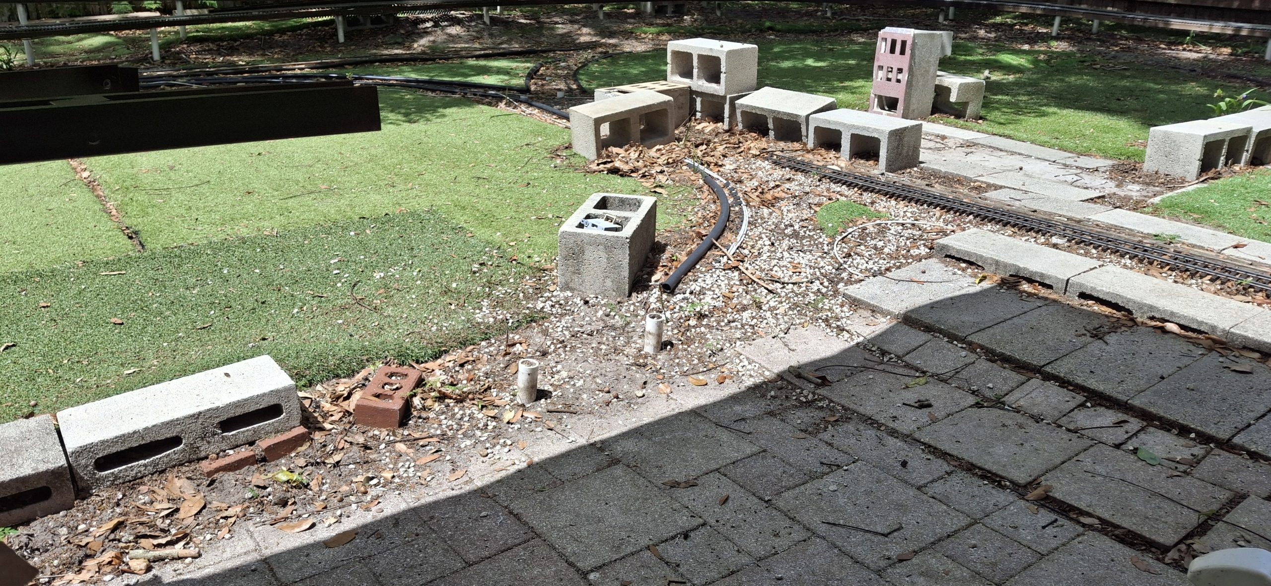
Hadn’t really planned on doing anything more than what’s necessary to replace the 20′ diameter track section and wye switch with 14′ diameter sections. Essentially we want to “hardwire” the Downtown loop to return to the mainline, reducing the layout to its original “dogbone” roots with two loops, one Downtown, and one over the deck.
The thinking was maybe we’d restore the wye in the future. Well, the future is now. What prompted this change? It all started with having to replace the stringers on the 20′ diameter section of the Downtown loop. It ended with finding the old homemade #5 switch design and bringing it out of mothballs. Somewhere in between we discovered that fixing the wye would be easier than not.
Since the track was still in place over the 20′ diameter section, the assumption was the stringer beneath was still in good shape. That was a poor assumption. Oh well, we’ll just make another 20′ diameter replacement while we’re at it. Slowly but surely that stretched into the next 14′ diameter section, then the next, and another after that.
Working toward the wye switch it became apparent all the wye stringers were rotted and need removed. Replacing each new section of the 14′ diameter stringers, it soon became apparent the posts weren’t arranged in a 14′ circle either. Turns out we’ll need another 14′ diameter stringer to reach the wye switch as well, once the remaining rotted stringers are removed that is.
Digging Out The Rotted 20' Diameter StringerRemoving What's Left Of The 20' Diameter Stringer The Pile Of Yellow Wood ShameGround Rated My @$$
If It Doesn’t Fit, Force It…
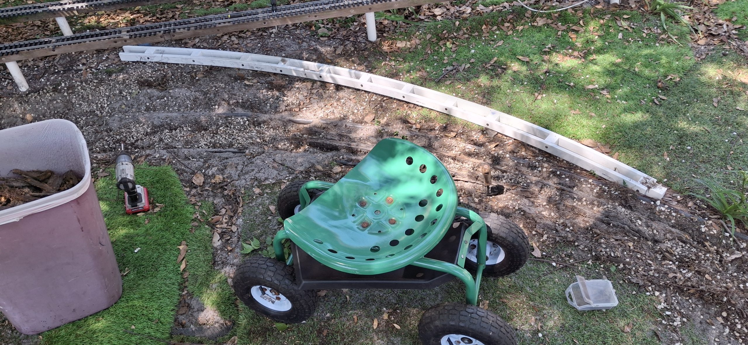
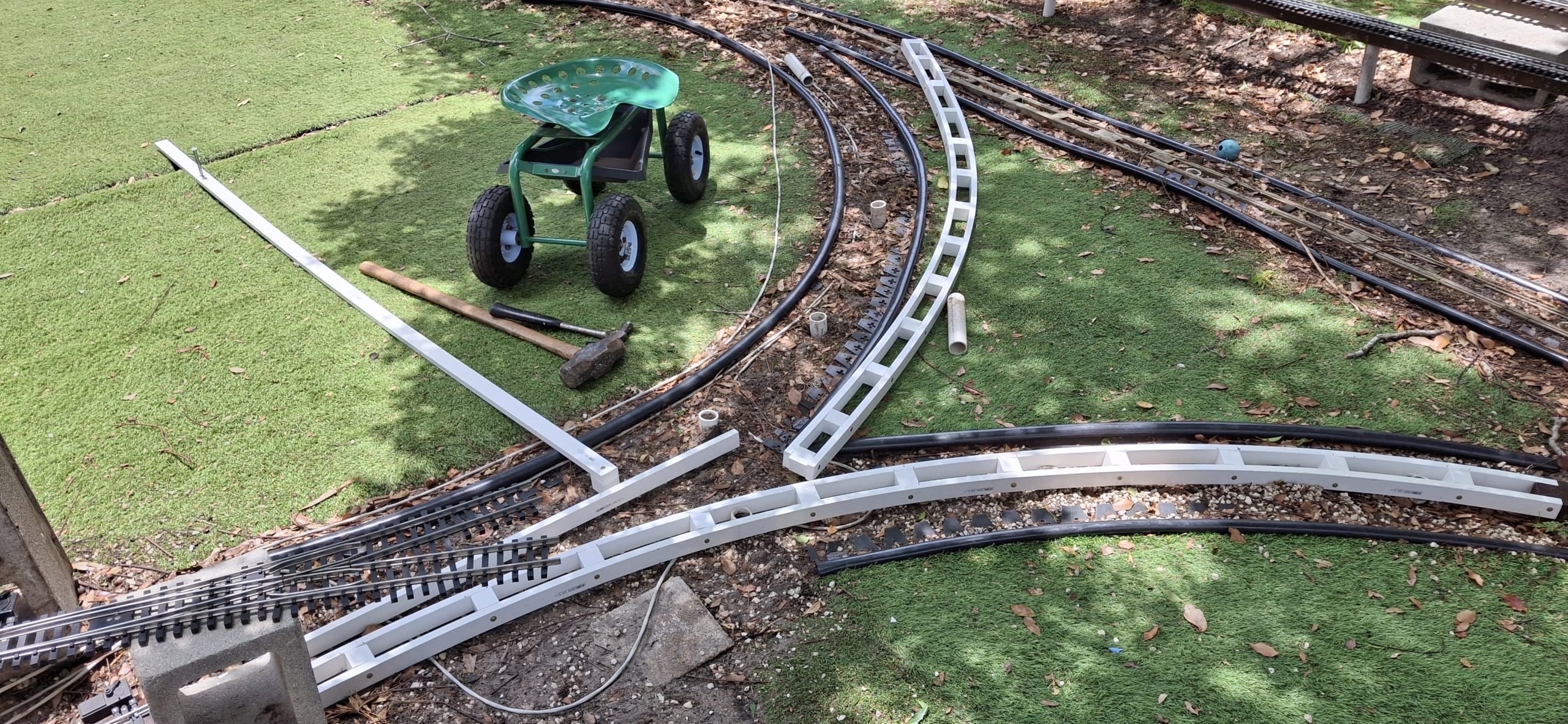
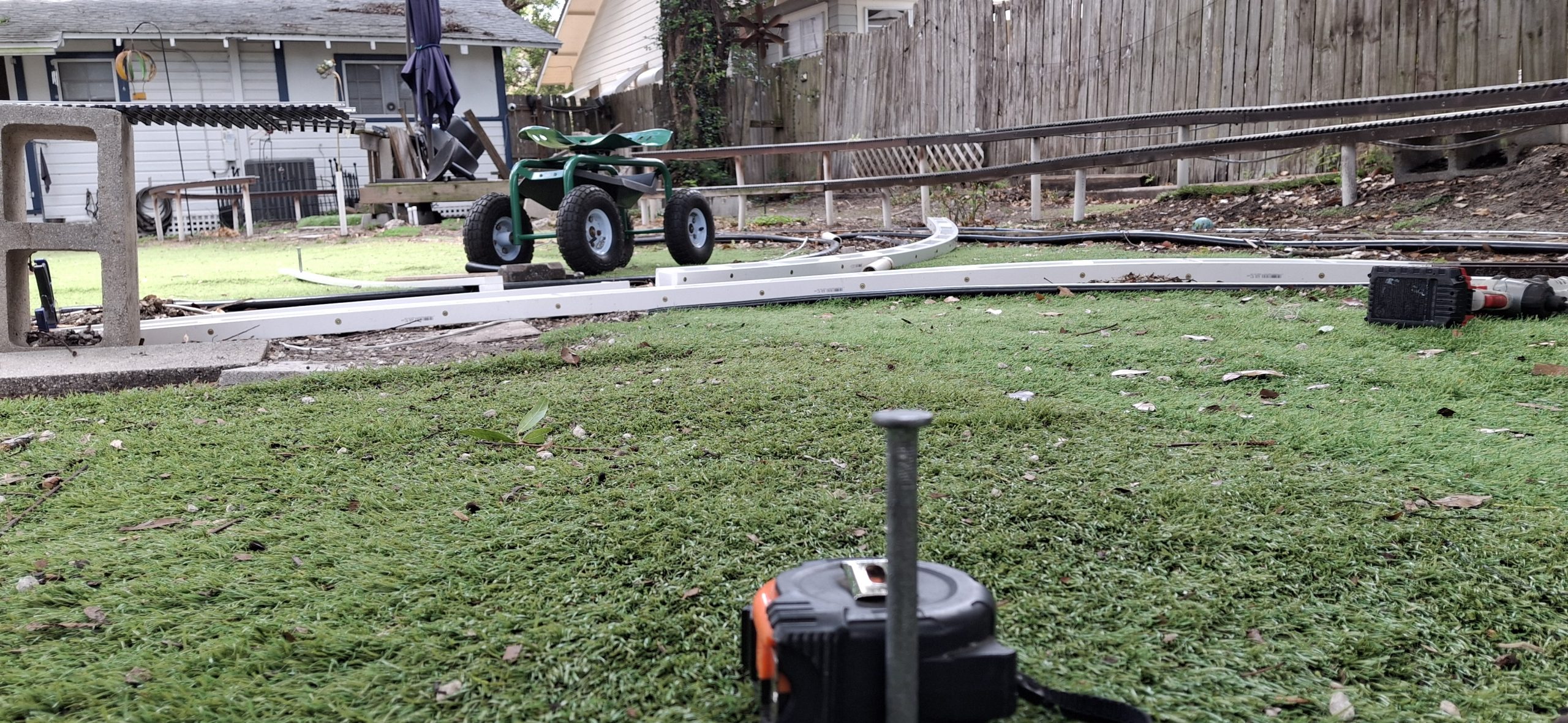
Force fitting those 14′ diameter legs of the wye may have made sense at the time, but now leaving them that way is more trouble than making it right. Time to break out that wye switch and take some measurements. We’re trying to locate the centers of those 14′ diameter circles, one on each side, based on the true geometry of the wye switch. But we’ll need something straight at least 7′ long.
Hmmm…. What do we have that is both long enough and straight enough? We have a whole stack of 8′ long PVC 1x2s not yet assembled into new stringers. One of those would certainly fit the bill. Marking out the centerline on the turf with a sharpie is close enough, but reminds me of previous opportunities lost without a more permanent center marker.
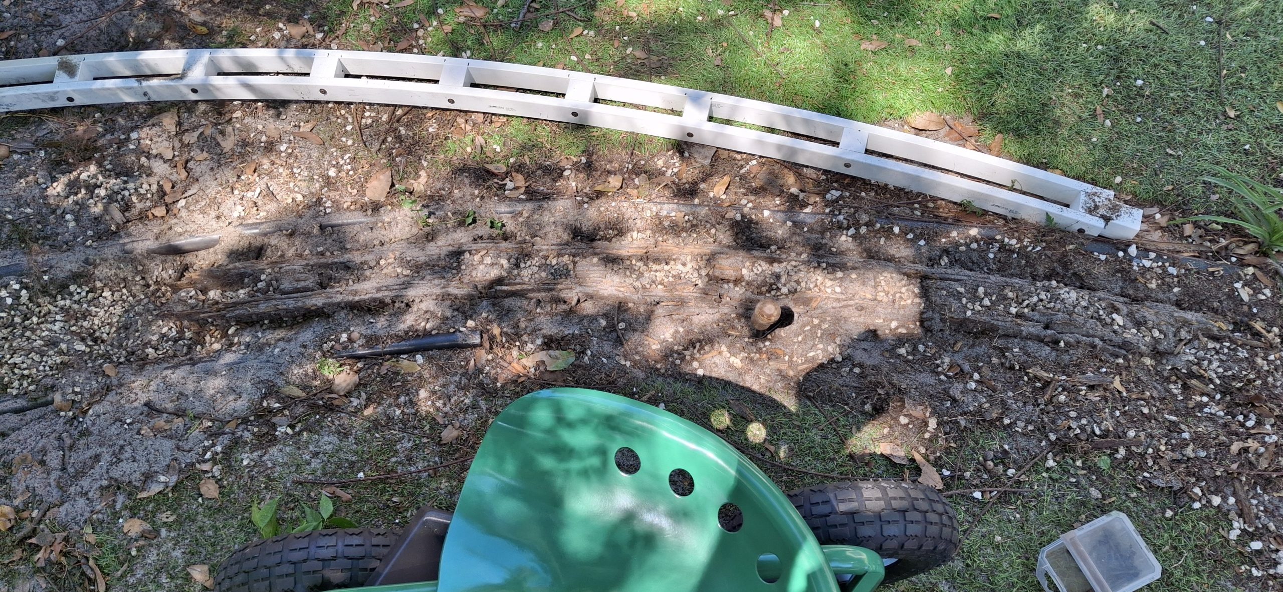
There has to be a better way to do this. Time to find one of those spare “turf nails”. Found a bunch of them in one of the drawers in the toolbox, and two different sizes no less! The idea is to “pin” the center with one of the larger turf nails. Beyond that, by attaching one of those 1⅝” spacers to one end of the 1×2 and drilling a hole to fit the nail marking the center at the other end, we have an accurate compass.
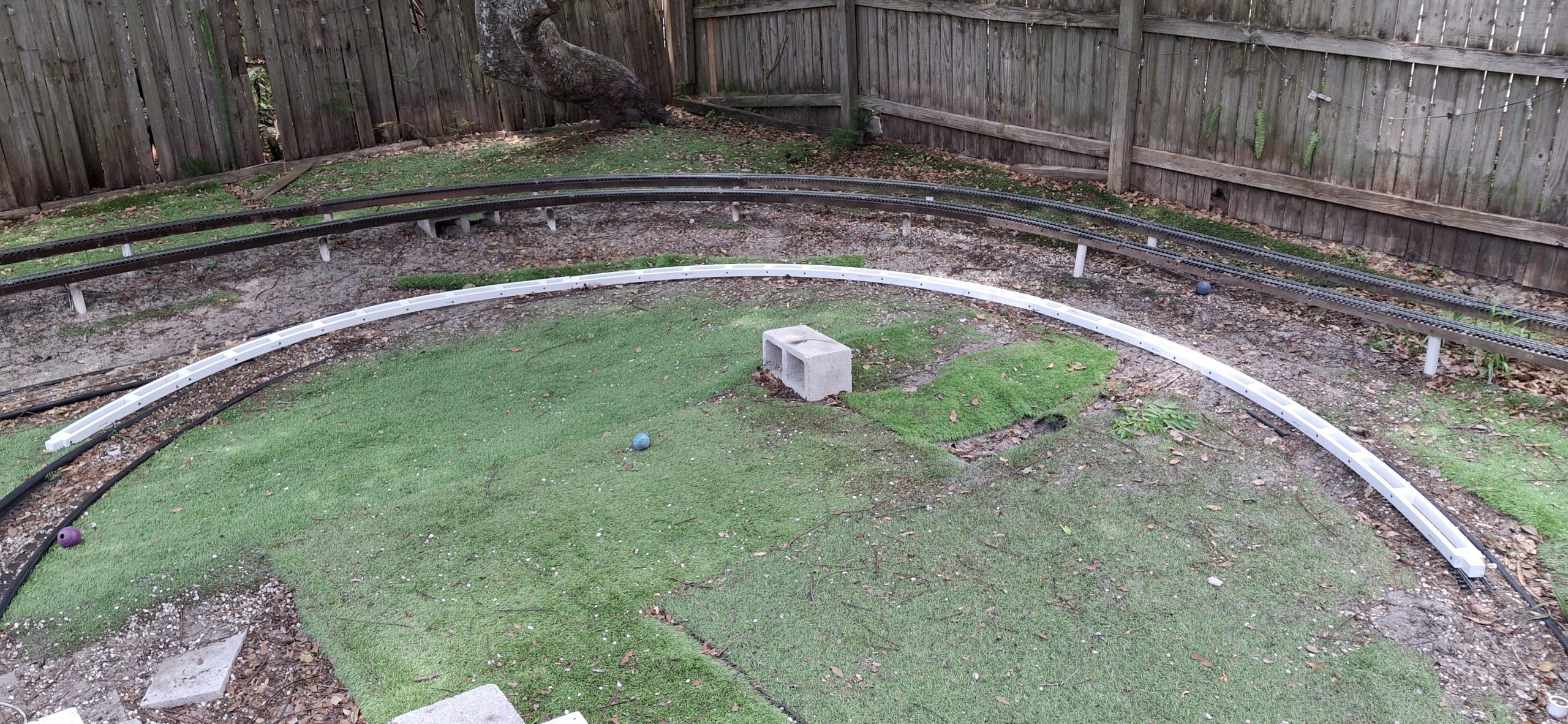
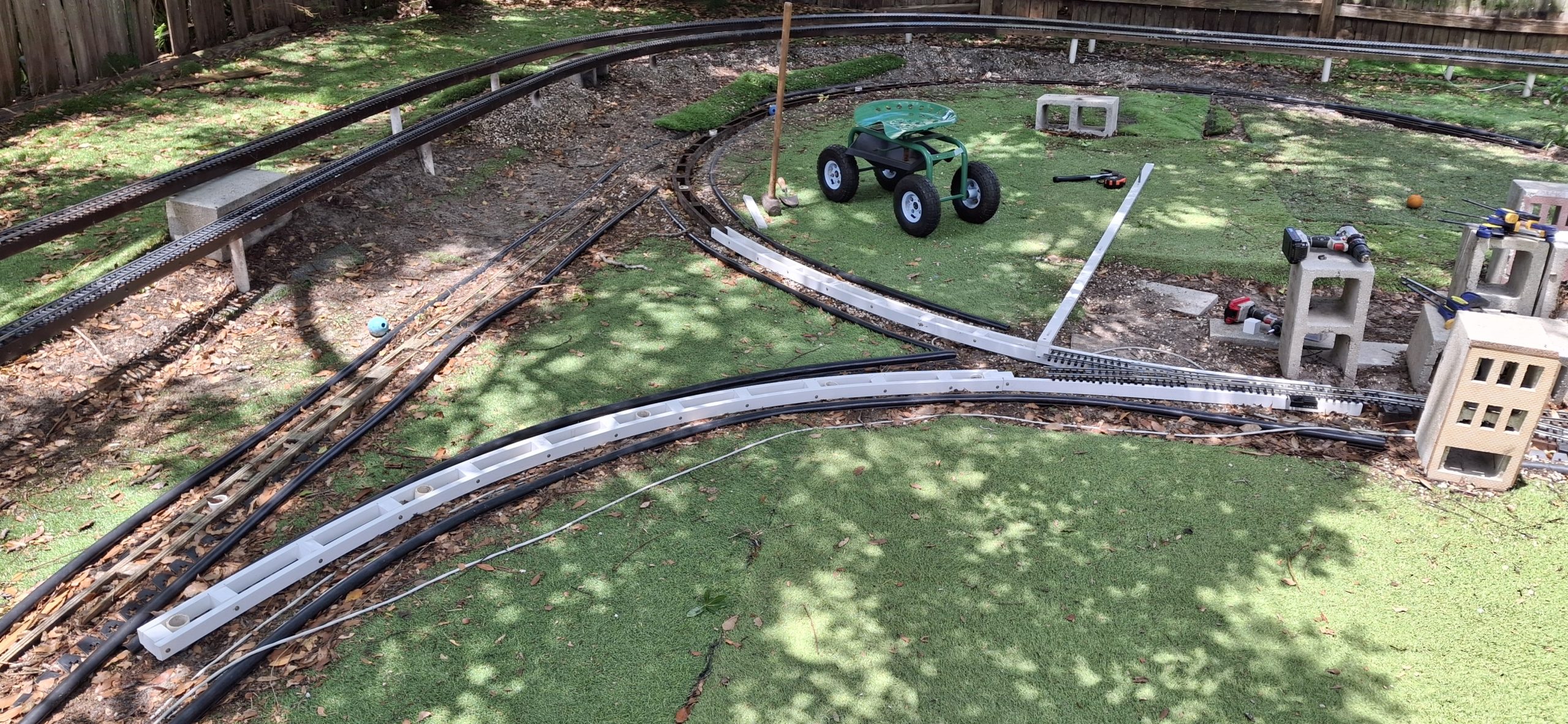
With our new PVC “compass”, we can “sweep” a 14′ diameter circle, holding the stringers in place with that spacer. It fits nicely between the two sides of the stringer and holds it in place while confidently driving a post into the correct location. That involves pulling out the existing incorrectly located posts with a set of Kleins then accurately smashing them back in with the sledge hammer.
Can't Get Enough 14' Diameter StringersUsing Our New "Compass" To Lay In The New StringersUsing Our New "Compass" To Lay In The New Stringers View Of The South Center From The North CenterStarting From The Correct Diverging Route AngleSweeping The 14' Diameter North Leg
All Kinds Of Wrong
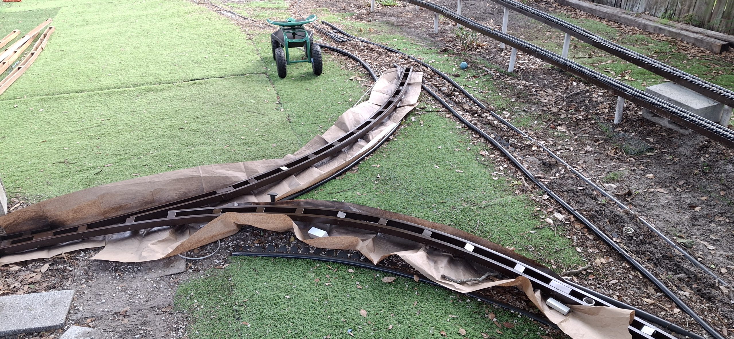
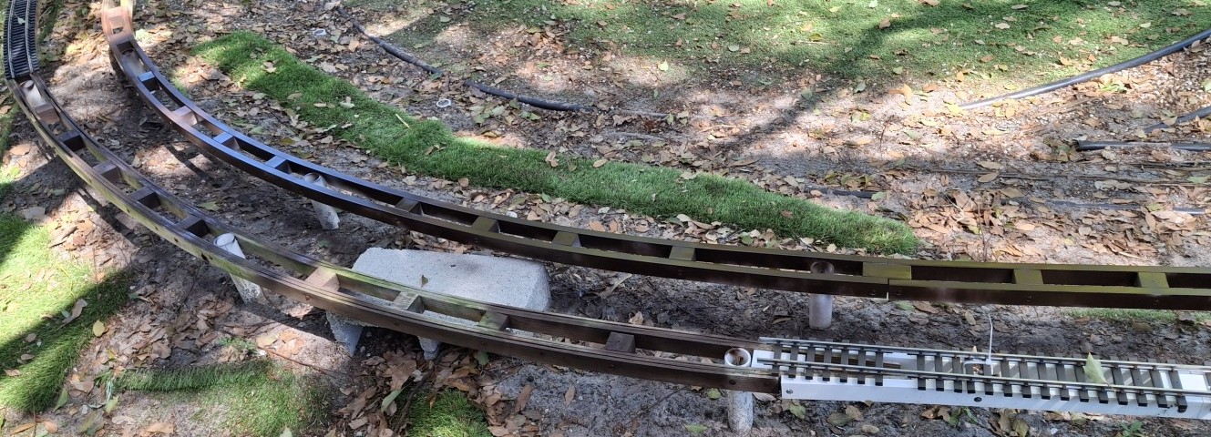
As helpful as our new PVC compass is for laying out the curved stringers, it also excels at pointing out all the mistakes in our original geometry. Both legs of the wye were off by more than twice the width of the track! No wonder the track refused to cooperate and go where it was supposed to without a fight. All kinds of wrong.
On the North leg of the wye, the closer it gets to where we need that curved switch, the more the radius relaxes into a wider curve. On the South leg, the closer it gets to those toe-to-toe switches, the tighter the radius gets! If you look closely at the pictures, you’ll see how far off the black edging is now. Good thing we’re using flex track for both curved legs!
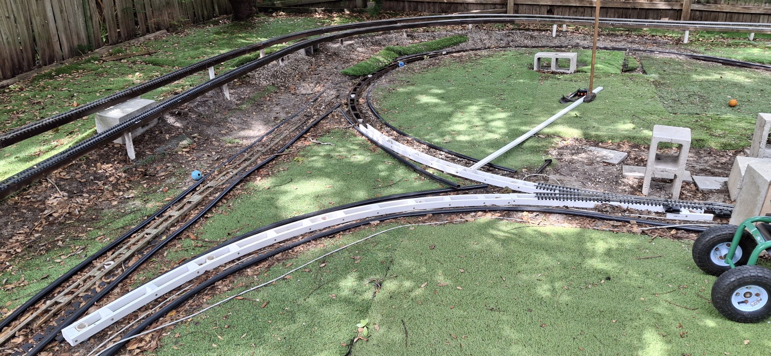
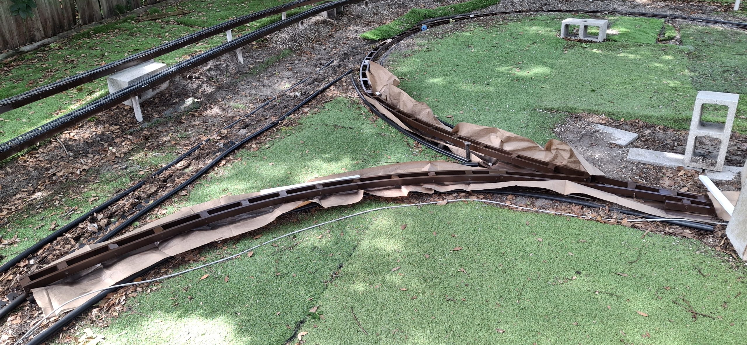
It may take some time with the rail bender to finesse the wonky curved flex tracks to fit properly, but it’s totally worth the effort. Both stringers now follow a smooth curve that fits the desired geometry. I just wish I’d painted those stringers before fastening them together! Nothing some strategically placed masking paper won’t handle.
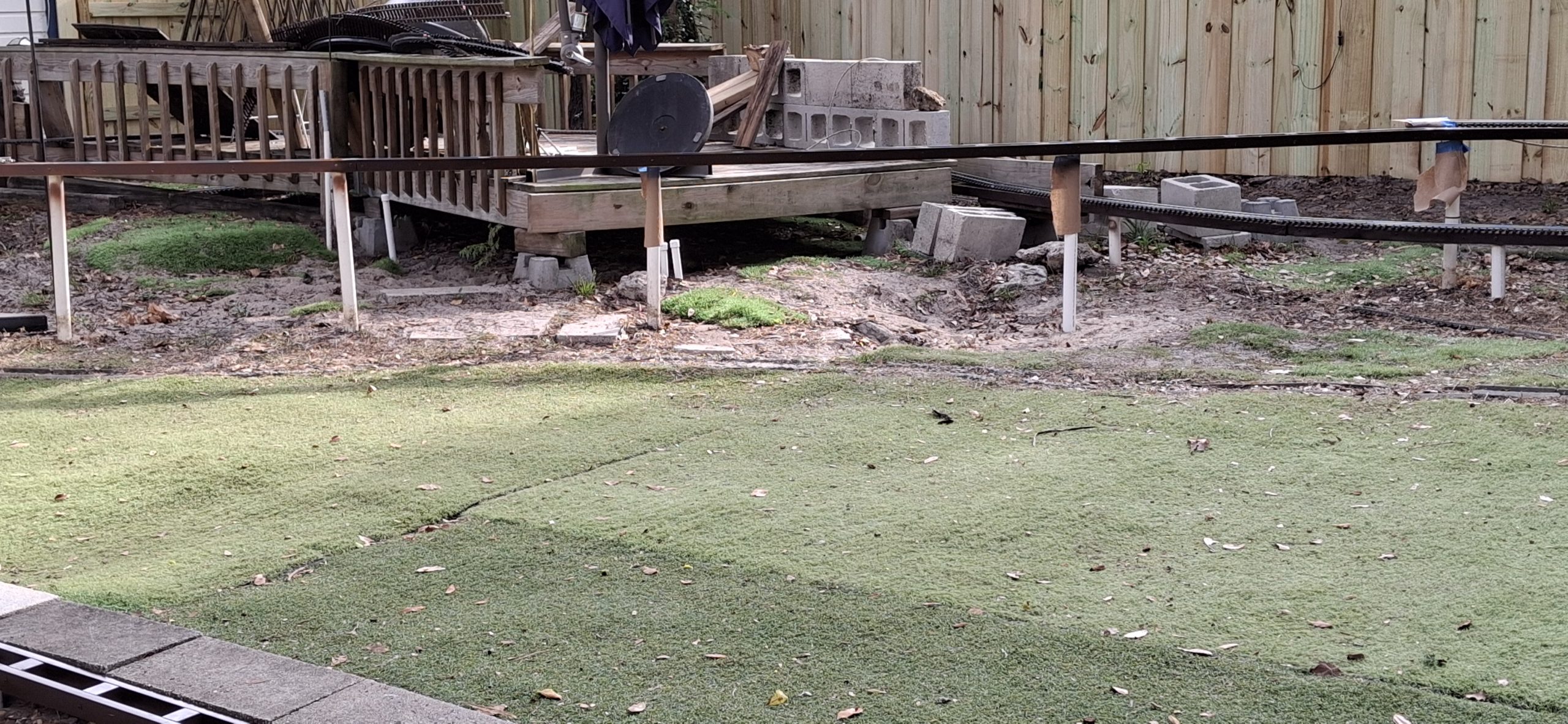
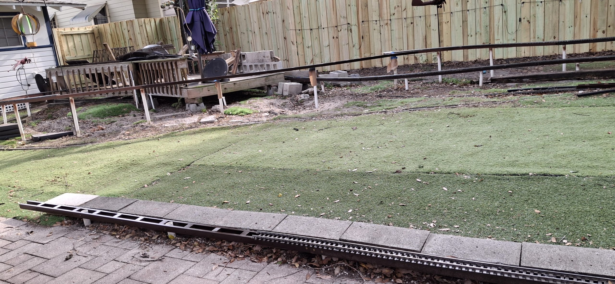
Ran Out Of Time To Replace The Straight Leg This Weekend Ran Out Of Time To Replace The Straight Leg This WeekendSPOILERS: Future Home Of The Curved SwitchTook Friday Off To Get A Jump On Finishing The Wye
So kind of a funny aside. A while back I asked Nick to pick up a couple cans of brown spray paint for me from Lowe’s. He got me two of the fancy adjustable nozzle Krylon brown and two of the 2X espresso color. I used those up weeks ago. The next time I was there, Lowe’s was out of the 2X espresso I wanted, so I got three with the fancy nozzle in dark brown. They’re also gone now.
Last time there I bought all the 2X espresso they had, the three left on the shelf and the remaining case of six I had to have an associate fetch from the rack high above using the huge rolling ladder thingy. After painting those wye stringers, I’m down to my last four cans! But I’m getting ahead of myself.
The only reason we’re talking about painting in the first place is because of protecting the PVC from Ultra-violet (UV) radiation, which breaks the bonds in the flexible long chain polymers, making it more and more brittle over time. Paint is a means of protecting the PVC from the UV degradation of baking in the hot Florida sun. An added bonus is it looks much better than bright white!
Hurricane Dropped Part Of The Tree On This Totally Destroyed 3' Track SectionThe Remnants Of The 10' Diameter Loops Behind The ShedLearn The Art Of Track Repair At Home - Repaired 3' Section
Time To Take A Fence Break
We almost got the wye finished, but had to stop and make sure we’re ready for the new fence to go in this coming week, the first full week of May (2026). So we also spent this last weekend pulling out the rest of the track and rotted stringers from behind the shed in preparation for the fence builders to come in and replace the fence. Wasn’t much left but the track itself and just a single 10′ diameter wood stringer still in fairly good shape.
Even that totally destroyed 3′ section of track came out, the one that hurricane Milton blew down a big chunk of the tree on that caused all the damage. Speaking of that destroyed 3′ section, I managed to get both rails straightened out and the tie strips back in place and screwed securely to the rails. Like it never happened! I was amazed that just sighting down the rails and some time with the rail bender was all it took.
But that wasn’t the only piece of track repaired. Add two 5′ sections to the list from yesterday. Just about every piece of track needs disassembled and the tie strips “reseated” over the foot of the rails before the track can be put back in place. Anyone who’s ever dealt with those annoying little Aristo-craft screws knows what a pain they are. My big hammy hands make it even more difficult, inevitably losing some of those fumbly screws in the process.
As an example, one of those 5′ sections was missing every fourth screw. I have some replacements but they only thread in a little over a turn before binding, like they’re the wrong thread pitch, so I gave up on that. Some are better than none. When you get right down to it, are they really necessary at all? Those Piko tie strips for the flex track have none and still hold the rails just fine.
Fence Break’s Over!
Fixing the track is about all we’re able to do while they remove what’s left of the old fence and basically build our new board-on-board fence in place, from scratch. I say they, but it’s basically one very dedicated individual, John, and he knows his stuff! Over the course of four days he nearly single handedly built our new fence. He had a “new hire” one day, but he quit and left early on his first day! We’re simply amazed by the quality and craftsmanship. And it looks awesome!
Judge for yourself. All but one of the pictures so far show the old, dilapidated fence in the background. Those pictures that follow will have the new fence in the background. Ann’s already out there stringing up the lights, and doing it the way she wants them done this time around, stretched straight and level. No sagging allowed! We even rerouted the dedicated extension cord around the back of the garage instead of draped over the track in front of the shed. Much better!
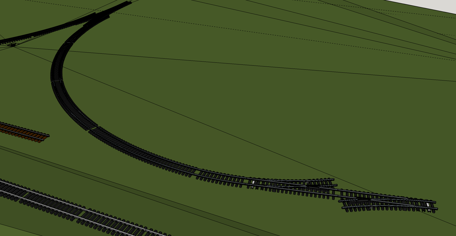
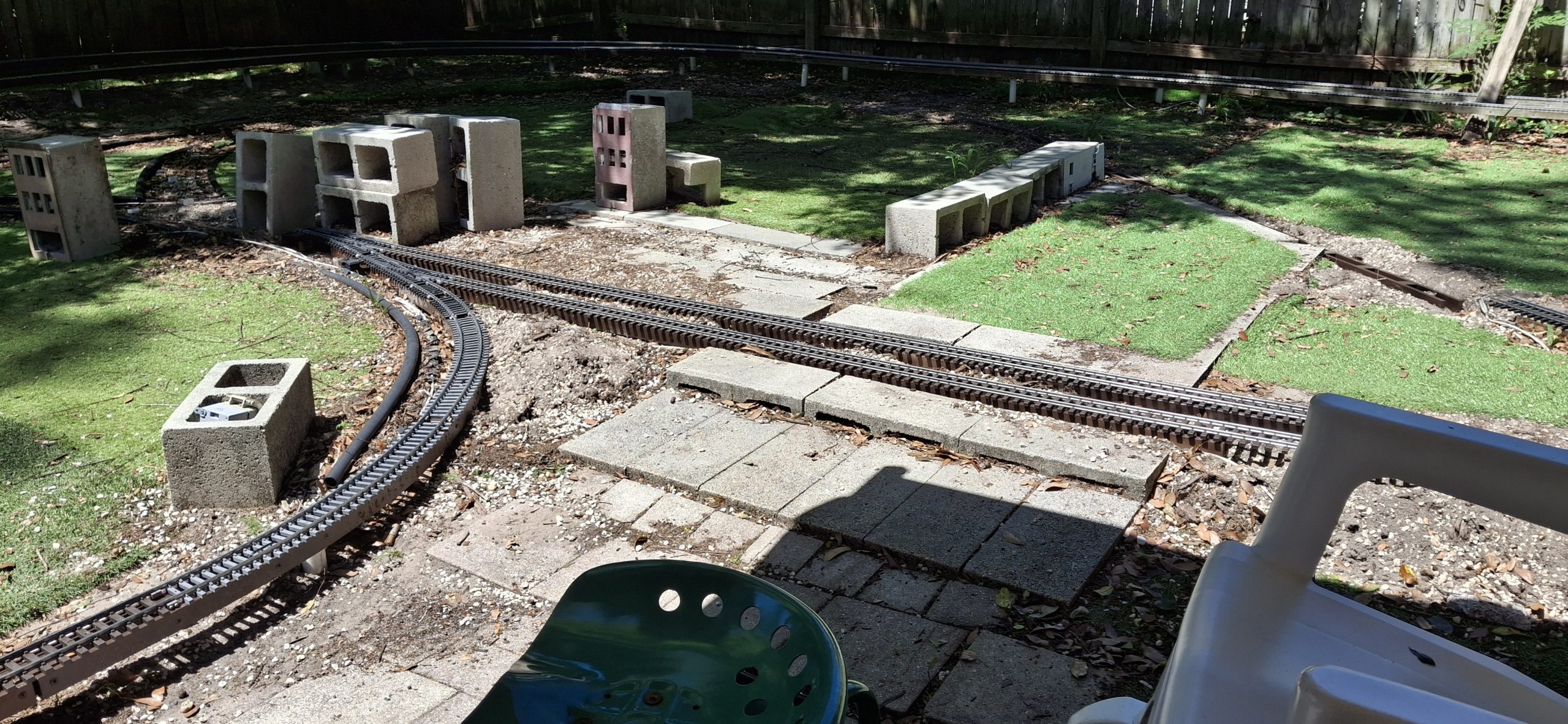
Time to get back to replacing the stringers. All the curved stringers we need are already finished, painted, and installed. Time for a bunch more straight ones. Two for the bridge section by the deck, two for the straight leg of the wye, and another to complete the station siding. Another weekend, another set of stringers installed. All but the straight leg of the wye. That’s going to take a LOT more work to finish.
Not only does the dirt need dug out, but there was turf under the old stringers, meaning it will need cut out of the way first, just to be able to get to the dirt under it! We’ll save that for next time. For now the progress is impressive. And more than we originally planned. But to make the wye a reality, we’ll need that curved switch. Good news everyone! That’s already in the works. I spent the week the fence was installed working on the design, captured in this post.
Somebody Order A Bunch Of Freshly Painted Stringers?The Only Thing Missing Is The Track And BridgesFinishing Out The Station Siding And The Bridge Stringers Nearly Completed Wye - Just Need To Dig That Straight Leg InSPOILERS: Future Home Of The Curved SwitchWye Switch Diverging Leg Detail
For A Limited Time Only
I’d been gathering the footage of the progress from the surveillance cameras, thinking they could be spliced together into a sort of time lapse montage. But then I missed the window to grab the footage from a couple weekends now. I’m surprised by this since I’ve been able to go back more than a week in the past. I can’t remember the last time I wasn’t able to. Oh well, I’m down to my last 3GB on a 4TB drive, not sure where I would have put it anyway!
Add the footage of the fence installation to that and we broke the bank, so to speak. I hastily rearranged data on the network storage server and removed duplicated items to make space for this video and more. I’m not real comfortable with the single point of failure state that left a lot of the existing captured video in, but I haven’t done anything with it years later, so chances are I’ll never do anything with it anyway and it’s just wasted storage. Time will tell.
For now, we’re busy with a single goal. Get. Trains. Running. Will we get there by Memorial Day? We’re definitely cutting it close with just one more weekend until Memorial Day weekend. I hate to leave you with a cliff hanger, but if you want to find out, you’ll have to stay tuned for Part III. I will admit we’ll be pushing it just to get all the stringers replaced, let alone all the track relayed.
Question? Concerns? Leave A Comment!
If you have any questions or concerns, please feel free to comment on this post. In any case, you’ll need to create a user account to do so. We don’t use any personal information for marketing or to spam you (see our privacy policy). We do it this way to avoid scammers spamming our posts. You’ll receive a verification email. Reply to the link provided to verify your email address. After that, it’s all automatic. No waiting on moderator approval! No spamming your inbox with useless advertisements and “Special Offers”. None of that nonsense.
Welcome back! We’re welcoming Spring with new springers, er… stringers. To celebrate the first day of Spring, we got out in the Barkyard to begin the annual stringer replacements. Well, technically it’s the second day of Spring, but close enough. We never expected this to become an annual event, but that’s what it is now.
Learning the hard way that modern wood products just don’t stand the test of time out in the elements. Not even when heavily treated to do so. Those wood stringers offer a sturdy base for our track and elevate much of our rail above ground. Inevitably those wooden stringers rot. Last fall, we decided to try using PVC to replace a few rotted sections.
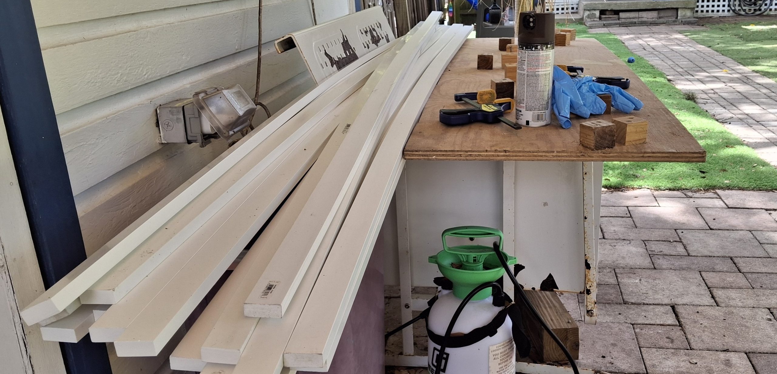
There are advantages to using PVC trim over pressure treated (PT) lumber. First is reduction of effort and waste. To construct wooden stringers, we rip a 2x4x8′ stud into not quite a dozen ¼”x1½”x8′ slats. It’s labor intensive considering the time spent at the table saw and it’s wasteful as each rip turns ⅛”x1½”x8′ into sawdust. That’s one third of the raw material converted directly to waste!
Another advantage of PVC stringers is ease of assembly. Each side of the stringer is now a single ⅝”x1½”x8′ PVC trim piece, not three slats that all need trimmed to different lengths when using the curve templates. I built those templates to help ease assembly, wrangling all six slats and a dozen spacer blocks into some semblance of order.
Before - Rotten Wooden StringersAfter - Soon To Be Rotten Wooden Stringers
Let’s Do This The Easy Way
Now it’s just a single pass with a pair of the PVC 1x2s, drill and screw each to the spacer blocks, then trim either end and done. It still takes about an hour to assemble an 8′ section of stringer, but it saves about another hour of ripping a 2×4 into slats, not to mention the countless hours of removing rotted sections and replacing them every year.
Speaking of those jigs, they’re not really necessary when using PVC. Assuming the posts are arranged in the desired pattern, circular or otherwise, just attach the spacer blocks to one side then fasten that in place along those posts. Attaching the remaining side is easy enough using clamps to hold it in place while fastening it to the first side and posts.
So far we’ve used the 14′ and 20′ curve jig. The 10′ diameter curves could be a different story. We skidded the shed out from the fence another 8″ a while back with the hope of fitting larger curves to replace those tight 10′ diameter sections. They were enough to get us up and running originally, but now we have flex track and a rail bender to fit any size curve.
Building 14' Diameter Stringer - New Stringers In BackgroundLeft End Overhang - One Leg Needs TrimmedRight End Overhang - One Leg Needs Trimmed
Getting A Head Start
Every year there’s a push to get trains running again. This year we’re starting earlier than most, in the past usually waiting until May to get trains running by Memorial Day. Some years that even stretched to July 4th. And every year it’s the same thing. Replace the rotted wooden stringers. As we said, it’s become an annual event.
Those concrete roadbed “bricks” we’re experimenting with work, but are much more labor intensive than posts and stringers, and nowhere near as sturdy and immoveable as we thought they’d be. Still working on how to streamline that process… Comparing the ease of replacing the rotted wooden stringers with PVC ones with the amount of effort using concrete bricks, it’s a no brainer!
So far we’ve replaced about 100′ of stringers, both straight and curved sections, but we’ve also taken up more than 300′ of track where the stringers had already rotted out over the past year or so and no longer held the track. We’re still behind the curve for getting trains running by Memorial Day, but we’re working hard to make that happen.
Corner PVC Stringer In Place And Painted Next To Wooden Stringer8' PVC Stringers, One Painted, One Not 8' PVC Stringer Next To "Plastic Wood" Stringer20' Diameter Curved Stringer To Bridges Corner Stringers From The Inside This TimeYet Another Inside Look At 8' PVC Stringers Inside Look At 8' PVC and "Plastic Wood" Stringers20' Diameter Curved Stringer And Rotted Stringer Disposal
Just Enough
The plan is to replace just enough track to have a continuous loop trains can run on. This would consist of the downtown loop, that North leg of the wye loops around through downtown along the mainline back to the elevated sections. The elevated sections need bridges in place to run trains past the deck and back to downtown.
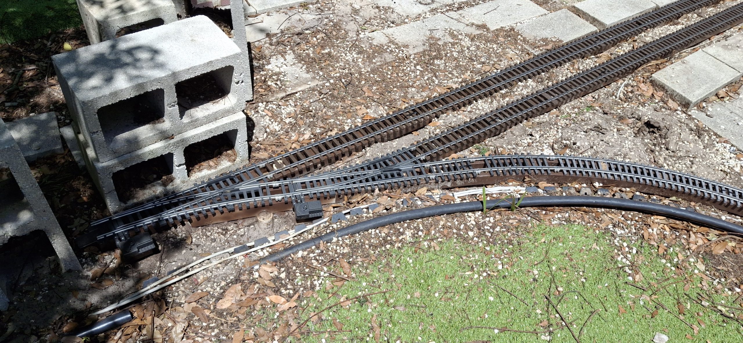
The lower loop around the deck and the other legs of the wye will have to wait. Essentially the mainline Downtown connects to the wye switch (West). The diverging legs of the wye arrangement go left (South) to the deck and right (North) to the downtown loop. The only thing missing to make it an operational wye is a switch connecting the North leg to the straight leg to the West.
But a standard switch doesn’t fit. When I first laid out that downtown wye section, I thought the Aristo-craft wye switch replaced a full 20′ curved segment of track. I found out the hard way it didn’t. Trying to fit those 14′ diameter curves to the diverging routes of the wye switch didn’t work as planned.
The angles were off just enough that it didn’t fit without having to resort to flex track and bending a tighter radius to make it fit. Without the wye switch in place, the 14′ diameter segments fit just fine. It may be better to redo that section to make it fit right while we already have it apart and all torn up anyway. We shall see…
The Downtown Wye ArrangementWye South Leg Toe To Toe Switch Arrangement
Making Progress
Amazing what was accomplished in a single weekend. All of the elevated sections are in place and painted with the track repaired and installed. That was easy compared to what’s next. The ground level sections, starting with the mainline and siding switches to the station siding. And there’s a reason for starting there.
Because of the “hiccup” with the wye switch not quite aligning with the diverging legs of the wye, that becomes the most important location on the layout. Everything has to be measured against and fit to that point. Why? Because the station siding just fits using 10′ diameter curves and the two wide radius switches. And that has to be the starting point for the wye switch.
Another consideration is the height of the mainline crossing Main Street into Downtown. The original track height is too tall by about the thickness of a concrete block cap, roughly 1⅝”. The quick and dirty way around that in the past was to just line Main Street with concrete block caps, simulating curbing, sidewalks and building foundations.
Future PVC Stringers Ready For AssemblyCutting More Spacer Blocks From PVC 2x2
It’s A Dirty Job…
Time to start digging out what remains of the rotted mainline and siding stringers. I need someplace to put all the dirt and gravel while test fitting the yet to be assembled replacements, but somehow I’ve managed to use all the five gallons buckets for something else.
A number of unused 16qt storage bins with lids are sitting in the garage, so they’re pressed into service. Fitting the new replacements fills two of them! I hadn’t planned on fixing anything more than the station siding, but as the digging exposes more and more of what remains of the other siding, the danger of exposed screws is apparent. Better fix it all while we’re in here.
Those 10′ diameter stringers have always been right at the edge of being too tight of a curve for any material, wanting to spring back to their original straight shape when removed from the jig. Thankfully we only need two sections (~60°), not an entire quarter circle (90°). It’s still straining to maintain its shape against the posts, and the screws are pulling out of the twisting spacers.
Station Siding Site And Mainline Main Street CrossingMainline And Sidings RestoredMainline And Siding Lowered For Main Street Crossing
Repairing The Track
About as common as replacing rotted stringers is having to repair the track. It seems that just looking at the track wrong will cause the rail to pull out of the simulated tie plates and spikes. Now consider three good sized German Shepherd “pups” constantly pounding on them. Add to that constant UV bombardment from our hot Florida sun baking them brittle and prone to breakage.
Just about every piece of track needs disassembled and the tie strips “reseated” over the foot of the rails before the track can be put back in place. Anyone who’s ever dealt with those annoying little Aristo-craft screws knows what a pain they are. My big hammy hands make it even more difficult, inevitably losing some of those fumbly screws in the process.
In the past I’ve tried to patiently coax the ties back around the foot of the rail using tiny screwdrivers and other tools with limited success. What usually ends up happening is the another tie gets pushed off the rail while struggling to hold it in place and fix the first tie. Anyone that knows me knows what little patience I have doesn’t last long with fiddly things like that.
Track Waiting For The New Fence Install To Be FinishedTrack In Need Of Repair Above And Repaired Below
Relaying The Track
Anyway, each track section is laid back in its place as it’s repaired. SplitJaw™ rail clamps are then installed to connect it to the previous section. Learning from past mistakes, when securing a single tie with a screw to the stringer beneath, either the screw pulls through the tie or the tie gets ripped free from the rail, now uselessly still mounted to the stringer.
We recently switched to using zip ties every so often to hold several ties to an joiner block of the underlying stringer. It’s much more forgiving using this method. The track usually has enough give that it simply shifts to the side when absorbing impacts. That’s not to say that the track can’t still be damaged, but it certainly takes a lot more effort to do so.
Pulling the zip tie too tight is a quick way to cause damage. The most difficult part is placing those zip ties when the stringers rest directly on the ground. It’s a struggle to feed them down through the ties, underneath the spacer block and then back up through the ties to secure them. But at least now the mainline and siding tracks are fully restored and in place.
"Main Street" CrossingsThe Most Important Place On The Railroad The Station Siding To The "Platform"The Station Siding Along The "Platform"
What The Future Holds
Another weekend, another part of the Barkyard restored. The next big win would be to get the rest of the ground level track in place, including the rest of the wye. That’s most likely a future thing though. As it stands, the wye really isn’t a fully functional wye arrangement. The downtown loop doesn’t have the option of returning to downtown and looping back to the elevated sections.
It’s only connected to the straight leg of the wye using a 20′ diameter track section in place of the 14′ diameter section. That straight leg does have a switch at the other end, allowing trains to run along the lower loop around the deck and then along the South leg of the wye back to downtown and the mainline heading East.
What we need is a 14’/20′ diameter curved switch to connect the straight leg to the other leg of the wye. It’s not clear in those screen captures though. They don’t make 14’/20′ diameter curved switches. At least not that I’m aware of. There’s not enough room for anything else to fit. I’ve designed myself into a corner.
Spoilers
Back to the drawing board! Years ago I had started designing a home made #5 switch to connect a diverging 14′ diameter route with a 3′ long tangent route. I think I originally had the downtown wye in mind. I’ve put all the details in this post dedicated to the new switch design.
There’s a new discovery in there as well. One that could have MAJOR impact on Downtown! Let’s just say I can’t wait for my new 3D printer to get here! It’s due to arrive in the mid April timeframe. I ordered it back in November of last year (2025). Think of it as “next generation” printer technology compared to my other “first generation” technology printers, where everything is manual.
I’m looking forward to not have to manually swap spools of filament mid print while crossing my fingers that something doesn’t screw up. This new one can handle four different colors in one print. The printer actually supports up to 16 colors at once, but I opted for just the four in a single ACE cabinet to begin with. Not sure where I would put the other three ACE cabinets anyway.
For A Limited Time Only
I had been gathering the footage of the progress from the surveillance cameras, thinking they could be spliced together into a sort of time lapse montage. But then I missed the window to grab the footage from last weekend. I’m surprised by this since I’ve been able to go back more than a week in the past. I can’t remember the last time I wasn’t able to.
Oh well, I’m down to my last 3GB on a 4TB drive, not sure where I would have put it anyway! I was waiting for the 8TB NVME drive prices to come down, but with AI and all the global upending lately, that ain’t happening. It’s DOUBLE what it was last year! They want $200 more for the 4TB drive I already have! Also nearly double! And they want more AI and more data centers?
Don’t get me wrong. I’m not Grandpa Simpson shouting at the clouds. I’ve used AI in increasing capacities at work since before the Large Language Models (LLMs) emerged. AI has its uses, but it’s not the panacea it’s made out to be. It’s wrong more often than it’s right. And when it’s wrong, it still takes a human to detect those mistakes and retrain it to reduce their frequency.
At some point those rough cut videos will reappear, but not right now. We’re making too much progress toward getting trains running again.
Question? Concerns? Leave A Comment!
If you have any questions or concerns, please feel free to comment on this post. In any case, you’ll need to create a user account to do so. We don’t use any personal information for marketing or to spam you (see our privacy policy). We do it this way to avoid scammers spamming our posts. You’ll receive a verification email. Reply to the link provided to verify your email address. It’s all automatic. No waiting on moderator approval! No spamming your inbox with useless advertisements and “Special Offers”. None of that nonsense.
Welcome back. This is the second part of our New Acquisitions For 2026 series. We highly recommend starting there if you haven’t seen it yet. We’ll be picking up where we left off in that original post. And as much as I want to say we saved the best for last, it’s doubtful this will be the last post about our latest acquisitions.
We’re very excited to have added these classic Aristocraft treasures to our collection. These “relics” are quickly becoming unobtanium. For those that remain for sale, the sellers are asking outrageous prices, presumably because of their perceived rarity. I’ll add them to my watchlist just to see if anyone is crazy enough to pay those ridiculous prices.
An added bonus in having them on hand is it allows them to be copied. And by copied, I mean their designs captured and perhaps 3D printed. Not all of the original design can be exactly duplicated, like metal driver wheels and gearboxes and such, and even some of the plastics will require redesign to support the limitations of 3D printing.
But for the most part, those missing and broken parts can be replicated fairly quickly, and to a reasonable degree of realism. But we’ll get to that in a bit.
Run In Stand “Power Pod” For USATrains Equipment
Where Did We Leave Off?
We’re getting set up to better test the mechanisms of these new acquisitions. That starts with a revised run in stand design that supplies power directly to the drivers. After the mishap with the test track, it’s time to get proper run in stands in place. But there’s a problem. The run in stands don’t have power feeds built into them.
Unlike their USATrains counterparts, Aristocraft doesn’t use power “skates” to enhance power pickup, but rather picks up directly through the wheels and axle bushings themselves. Our 3D printed run in stands rely on a separate “power pod” that feeds power up from the rails directly to those skates.
For the most part, a set of test leads can be clipped to the wheels of the pony truck on Aristocraft equipment. But on the custom Mikado, the power leads appear to have been deleted, presumably fallout from the DCC conversion. The main drivers still feed power from the track, so time for some mods to the run in stands themselves.
The initial thought is a quick and dirty feed through the bearings, thereby incurring the wrath of every jackal and troll on the internet, screaming “It will ruin the bearings!” in the comments. Well, stand down. That won’t work. Ask me how I know…
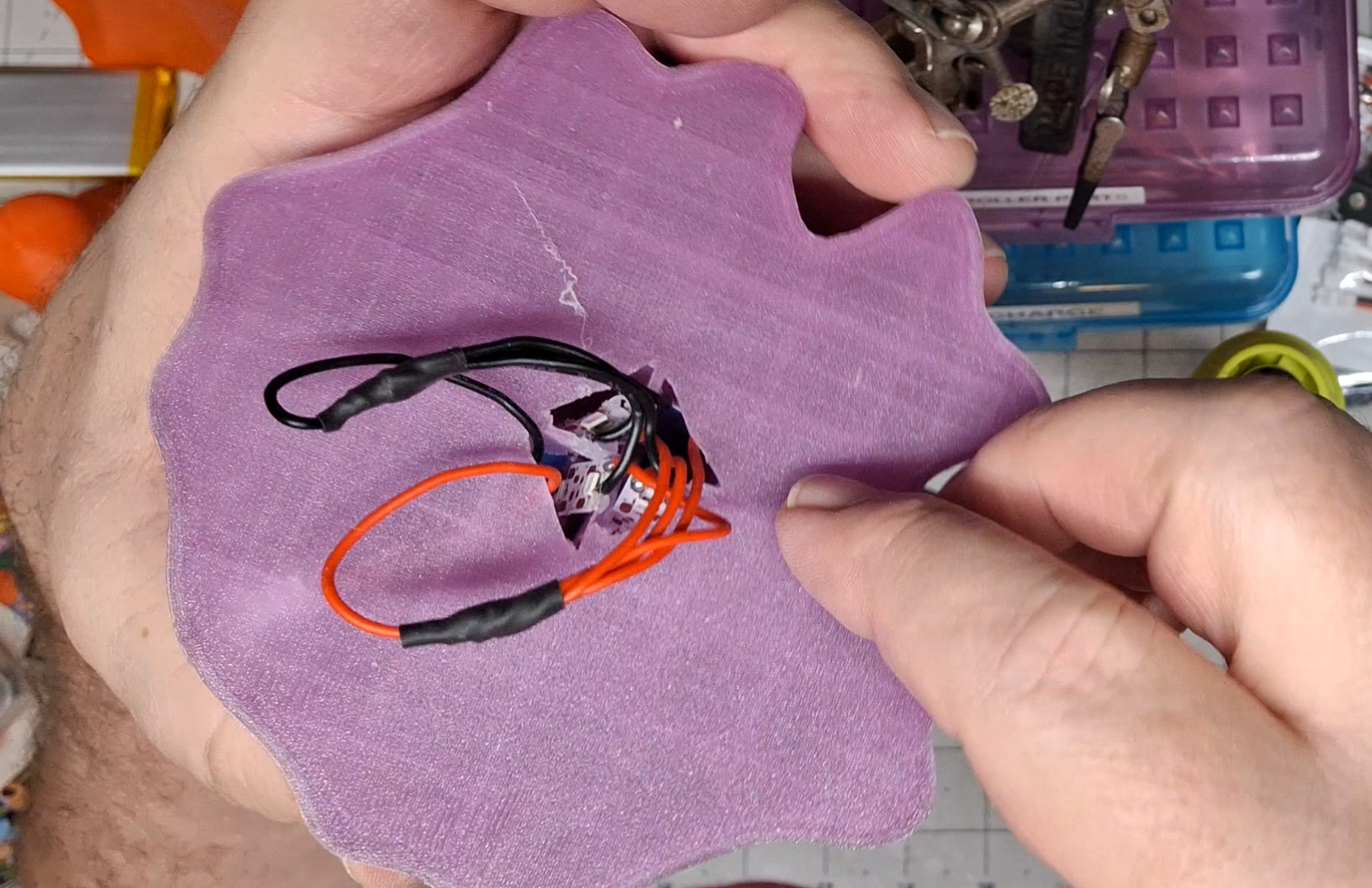
Attempt To Add Power Feed Thru Run In Stand Bearings With Copper Tape
That Would Be Too Easy
Unfortunately running the copper tape up from the rail to the inner bearing race doesn’t work. Apparently these bearings use plastic or ceramic balls because there’s no electrical continuity between the inner and outer races. Figures. That would be too easy…
So now what’s the plan? The only idea that comes to mind is some sort of “feeler” contact that rides directly on the outer race to feed power to it. That leads to thoughts of etched brass or stamped phosphor bronze contacts. Neither is quick considering the amount of time searching online to find something that already exists and will work.
Next idea. 3D print an insert to the existing run in stands with some sort of “springy feeler arms”. The initial sketches quickly point out the drawback of an insert over the bearing bosses. There’s not enough space for an arm that’s long enough and flexible enough and still only lightly contacts the outer race. Lightly is the key idea here.
Next idea. Just make an insert thin enough to fit between the sides and the outer race and cover it with the copper tape. The outer race will directly contact the copper tape on both sides. It could actually be on just one side, but we’ll see how well this works. The thickness of the insert is entirely based on trial and error.
New Power Feed “Inserts” For Existing Run In Stands
Tested?
A number of “prototype” inserts of various thicknesses are tested. The final thickness of the insert is between 1⁄16″ (~1.6mm) and 0.08″ (2mm). The trade off is increased drag on the outer bearing race vs. reliable electrical contact between it and the copper tape. The proof of the pudding and all that…
Four run in stands are quickly modified and pressed into service. And they work! Well, maybe I shouldn’t get so excited, they work most of the time. That trade off we talked about is in play here. If I press against one of them to narrow the gauge between it and the other side, the engine runs for a short time, then stops until I press it again.
This may have more to do with the rickety nature of the run in stands’ clamping force on the rail than the actual bearing contact with the copper tape. The original design opted for speed of production and not overall stability. Looking back, there are two areas for improvement in the original design. But we’ll get to those in a bit.
Thankfully there are recordings of the various engines tested, my memory not being what it used to be. They may become more of those “rough cuts” videos in the near future, but for now, they help me to remember which ones run smoothly and which ones still need work.
Custom Mikado Innards
Testing The Custom Mikado
The custom Mikado is doing well up until the last run, when that growling bearing noise started and became much more pronounced. Hopefully it’s just a lubrication issue. The Mikado from last year needs a new front drive shaft bearing in the front driver axle gear box. Its rusty appearance was a dead give away.
It may be the same issue here with the custom Mikado. That bearing faces forward and any moisture to be found will hit it head on. Won’t know for sure until we dive deeper into the mechanism. That’s not in the cards at the moment. We’ll save all that time consuming effort for later.
The cab and boiler were removed and it was all open at the time of testing. That’s when the Digitrax DCC decoder and Dallee sound card were discovered. Which reminds me, I still need to connect a speaker to test it. That is, once I figure out which of the three connectors goes to the speaker. May go straight to the horse’s mouth just to be sure.
Southern Tender All Clean And Shined Up Sporting New Wheels
The Southern Tender
There was a period between testing the custom Mikado and testing the Pacifics where the effort was devoted to the Southern tender. The wheels are a total basket case. The listing showed three of the four wheelsets in pieces, but it arrived with all four wheelsets in pieces. It has two Aristocraft couplers, including one where the drawbar should be.
First it’s disassembled and cleaned, including removing and scrubbing the top, then polishing the brass grab irons and the uncoupling lever with bar keepers friend. After straightening it of course. Funny story. I straightened that uncoupling lever to where it was barely noticeable, and spent the time to polish it, only to break off one of the levers!
I was a bit miffed at the time, mainly because of the wasted effort, but quickly got over it and ordered some 1⁄16″ brass rod to fabricate a replacement with. Considering that’s all cosmetic and we’re thinking of redecorating it to PRR anyway, we’ll save that for later. The OEM sound card checks out, so that’s a win.
Fabricated Decoupling Lever Replacement Comparison
Cosmetic Issues
While we’re discussing cosmetic issues, let take some time to discuss some of the common ones. Let’s start with missing parts, by far the most common problem with all our new treasures. If they’re not missing altogether, the cow catchers are broken into pieces. Thankfully in every case the mounting screws are still there in the front bolster.
As the saying goes, “All the bells and whistles…” are just as likely to be missing. In most cases, if the bell is missing, the bell harp is missing or broken as well. A significant number of engines are missing their air pumps too. One of them is even missing a cab window!
With the exception of the clear window material, replacements for all of them can be 3D printed. Once the designs have been captured that is. That’s the hard part, and involves trial and error fitting the design to the part so that everything looks and fits right.
The last of the 3D Solutech brown filament is still loaded in the old 3D printer, used just minutes ago to print the run in stand inserts. It takes a number of design iterations just to get the bell harp close. It’s not an exact match to OEM by any means, but it’s close enough to get the job done, and looks good doing it.
Adding All The Bells And Whistles
Parts Is Parts
Next is the bell itself. Again, it’s not an exact match to OEM, but close enough. The bell hanger is a tough one to print as one piece without supports. As small as it is, removing the supports would most likely break the fragile part.
To avoid supports a compromise is made. Printing it as two halves, flat, back to back. The two halves are then folded together along the small hinge points between them and glued together into one solid piece. This is then glued to the top of the bell to create a complete bell assembly that will fit between the arms of the bell harp and pivot freely.
The whistle has just as many parts, and just as tiny, if not more so. Difficult to handle to say the least. While this probably could have been designed to be two halves hinged together as well, no matter where the seam is placed, it will be visible. It’s similar to the “parting lines” left behind where the OEM injection molds come together.
To avoid that the chime and top are printed as one part, and the bottom another, both standing up. The mount is printed flat. The top and bottom parts are glued together to form the whistle itself, then the mount glued to the flat part of the cutout in the chime, snug against the bottom. The end result is a nice, round whistle with no visible seams.
3D Printed Cow Catcher Replacement
We’ll need replacements where the cow catcher and parts are missing altogether. Same for the air pumps. Once again the solutions are a multipart approach. The cow catcher has steps that would present an abrupt overhang, difficult to 3D print without supports. So those steps are printed separately then glued to the main assembly.
A similar situation exists for the the air pumps, where 3D printing the lower and upper cylinders together presents an abrupt overhang, difficult to print without supports. The lower cylinders are printed as one part, the upper cylinders another, and the piping a third. The piping is printed as two halves. All are glued together into a single assembly.
The air pump could be printed as two halves, but that would lead to “layer lines”, or “staircasing”. The drawback to printing a round object is the boundaries between the uppermost layers become exaggerated and obvious to the eye. More simply, the top looks more like a stack of slabs, too thick to maintain the illusion of roundness.
The only items that remain to be designed are the cab window frame and all the crosshead pieces. The clear part of the cab window will start as a piece of clear styrene of the proper size with the 3D printed frame overlayed on it. The crosshead is a future project due to the many pieces involved.
A Dusty Relic With New 3D Printed Bell, Bell Harp, Whistle, And Two Stage Air Pump
Color Matching
Just as difficult as matching the OEM part shape and size is matching the color, at least for B&O royal blue. Black is not black, but many different shades, and can be shiny or matte to boot. Matching the bell and whistle gold color to the actual brass color is just as challenging. That silk gold is too gold!
It’s comical how the “gold” paint pen looks more like brass yet better matches the color of the OEM bell and whistle. Oddly enough, that same bright gold looks fitting on the NYC Pacific, with its tarnished and dull brass grab rails looking almost blacked out. Being lazy about it and just leaving it that way for now.
The Prussian blue is a close match to the B&O blue when applied over the Navy blue 3D printed parts. Searching for the Prussian blue color online yields two dominant, yet different versions. One looks very close to the B&O blue and the other more saturated, with a somewhat more greenish tinge to it.
The search also turned up a post on the Railway Preservation News forum (rypn.org) with an actual reference to the PPG 15504 number, specifically named “Bando” blue, along with some other railroad color resources.
If you’re interested in obtaining the STL files to print your own replacements, leave us a comment and we’ll be happy to email them to you. See the instructions at the end of the post. But for now, let’s get back to testing.
B&O Pacific Running Smoothly On The Test Stand
Testing the B&O Pacific
The next unit under test is the B&O Pacific. With the exception of the smooth drive operation, everything else is less than satisfying. During the initial test on the run in stands, the valve eccentric crank on the fireman’s side breaks off! That’s about the time I noticed the bent grab rail and broken stanchion too.
Beginning to wonder if they dropped this thing when packaging it for shipping, or maybe just the packaging for shipping itself did all this damage. The listing picture shows the headlight mounted and the wires intact, the grab rail straight, the stanchion mounted where it belongs, along with the cow catcher.
Looking closely, I can see the cracks in the crank arm, so perhaps well hidden pre-existing conditions too. Nothing a little TLC can’t fix, but certainly not disclosed in the listing! A short diversion to design and 3D print a replacement later, the broken pieces are glued back together and pressed back into service.
Found the pieces of the of the cow catcher, missing when I went to glue it back together, along with the headlight in a separate package, I might believe a shipping mishap had they been found just floated around loosely in the box everything was shipped in. The separate packaging’s a deliberate attempt at the time of shipping to assure they’re found.
NYC Pacific Running Like Crap On The Test Stand
Testing The NYC Pacific
On the rails with it is the NYC tender to test the PH Hobbies sound card. It works. It has reed switches for chuff input, with a magnet glued to an axle, and two more for bell and whistle triggers. I grabbed a magnet and tested the bell and whistle too. Sounds like it gets stuck in a loop using the startup sound at idle, but who knows?
Swapped out the B&O with the NYC Pacific. Yeah. You guessed it. For all that “New Motor Block” bullshit, this thing sounds like a playing cards against the spokes of a bicycle wheel. Just a terrible, constant clicking noise, like slamming the car into park while it’s still moving. We’ll save all that effort for later.
For as much of the description that was dedicated to singing this thing’s praises, it certainly doesn’t live up to any of the hype. They left out the part that the new can motor installation didn’t work out as expected and more work is needed to assure reliable operation.
Awful Solder Job On New Can Motor- Now With Added Foam
NYC Pacific Follow Up
Fast forward follow up. It’s a new can motor alright, if the absolutely terrible soldering job on the leads is any indication, and no “built-in” fan. It’s sealed in a can, hence the name “can motor”. Where would you “build in” a fan? Where would it draw air from when there aren’t any openings in the can? Whatever.
It’s a can motor that’s not mounted to anything. It’s just “free floating” between a moveable, semi-circular support that can slide along its length and the cover, which screws to the bottom of the frame and has a set of stops on both ends meant to contain the OEM motor block.
The rear stop’s been hogged out to allow clearance for installation, but the motor is free to move back and forth. With it all the way forward, the universal starts binding. Slowly moving it back, the clicking begins as the ends of the brass universal “spider” start impacting the sides of the plastic tunnel between the motor housing and the drive shaft.
For now, a small chunk of dense foam packing material from the new filament drier holds the motor forward, preventing it from sliding back and forth. Long term, the can motor has three threaded mounting holes on its front face that can be incorporated into a new motor mount, yet to be designed and 3D printed.
Milwaukee Road Mikado #481 Running Smoothly On The Test Stand
Testing The Milwaukee Road Mikados
Thankfully testing the Milwaukee Road Mikados goes smoothly. Having the test track and run in stands already dialed in from the custom Mikado helps speed up the process. Both run smoothly with no issues. Lights work. Not sure about the smoke units though.
Inadvertently tested one of the other engines, either the custom Mikado or the NYC Pacific. Don’t recall which. Do remember the smell of something burning then realizing it’s the smoke unit was on. Turned it off so as not to burn out the heating element. All the smoke fluid is out in the garage, so nothing to test with anyway.
Don’t normally run smoke units for a number of reasons. First is the risk of burning out the element, or worse yet, melting something irreplaceable because of it overheating. Another is the limited fluid reservoirs, spending more time constantly topping off smoke fluid than actually being able to sit back, relax, and enjoy watching the trains run.
Even when running with the smoke on, it’s not very impressive. The smoke is pale white, not the dark black belched from the stacks as the firebox was stoked in anticipation for heavy workloads. Same with the old school first and second generation diesels we run. They belched black sooty smoke until the turbochargers could spool up.\
Milwaukee Road Mikado #465 Running Smoothly On The Test Stand
Where Have All The Tenders Gone?
Another follow up, searching for Aristocraft long steel tenders for sale online turns up very little, and for the few I did find they want $300 or more! What is going on? It’s like the universe knows I need one and they instantly become scarce and expensive at the same time! Seriously, where did all the reasonably priced tenders go?
Guess it’s time to look at scratch building something… Or designing and 3D printing a reasonable facsimile. If that’s the case, maybe I’ll grab a Vanderbuilt tender instead and create designs for both. That’s if I can find one and it’s under $200. At least I found a source for the 31mm wheels and already have the solution for all wheel pickup.
Need to figure out the bending jigs for the grab irons and decoupling levers and such. The replacement decoupling lever fabricated for the Southern tender was all hand made using my “eyecrometer” to measure and gauge where to bend. But that’s a problem for future me.
Burlington Long Steel Caboose With Working Smoke Stack
New Cabeese
Just scored an Aristocraft Long Steel Caboose in the CB&Q Burlington Route livery for $80 and shipping. The one with the pot belly stove that really smokes out the stack. It was one of those “Make Offer” deals on eBay. Scored another “Make Offer” deal in the PRR livery for $75 and shipping.
Also scored a pair of Aristocraft stainless steel #6 turnouts (ART-20330, ART-20340) for $300 and shipping. Well, tax and shipping, so roughly $350 for unobtainium. They were originally listed for $399 with a “Make Offer” deal as well. Seldom listed, in the past they were either bid up too high or someone had already pulled the “Buy It Now” trigger.
I do like the “Make Offer” style listings better. Most of the time the seller accepts my offer. But sometimes sellers counter with something too close to the original price. More irritating than a counter offer that’s not made in good faith are the sellers that send an insulting offer shortly after adding their item to my watchlist.
It’s almost like they’re saying, “I know what I got, no lowball offers”, before even making an offer! Most of the time those are the listings I watch to see if they actually sell for that price or just get perpetually relisted at the same, ridiculously high price. When everything else is listed at half what they’re asking, it seems ridiculously optimistic.
But enough griping about the pitfalls of online shopping. Let’s move on! The matter at hand centers around improving the testing arrangements.
PRR Long Steel Caboose Arrives Tomorrow
Improving The Testing Experience
If the experience with the runaway custom Mikado taught me nothing else, it’s that we need to come up with some improvements to the testing arrangements. A good start would be a dedicated test track power supply, complete with reverse, and possibly other features.
The current situation relies on the bench supply and a set of test leads with large alligator clips on the ends. One end clips on the output of the bench supply and the other on the rails. This is less than satisfactory in a number of ways. First is the potential for another runaway experience.
As diligent as I try to be with setting it to back to zero output before turning it off, I sometimes don’t. Imagine turning it off with the notion of turning it back on a short time later with the same setting for further testing, then getting distracted and not going back to it, let alone setting it back to zero. Next time it’s turned on, it’s not set to zero.
Just had this happen when attempting to test some 12V LED bulbs with a screw base (E5.5) that fit LGB equipment. Connected up the socket to the bench supply, threaded in the bulb, turned on the supply and… You guessed it. Set to much more than 12V!
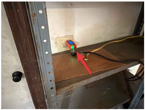
Another drawback of using test leads is getting the polarity wrong 50% of the time all the time. For whatever reason I can’t seem to remember which rail needs to be positive relative to the desired direction. A dedicated test track power supply with built in reverser and a dedicated polarized cable connection to the track would solve that problem.
Time to pull one of the many block control prototypes out of mothballs and dedicate it to the task. Maybe even take the time to add the DCC-EX support to it now that we have that custom Mikado with the Digitrax decoder inside. Thinking about replacing those analog meters with a single digital display too.
The digital display allows software control over the context of what’s displayed rather than dedicating a large area for just voltage and current readings. It also allows for size reduction. While we’re on the improvement bandwagon, time to improve the run in stands and eliminate that “rickety” feeling.
Improving The Run In Stand Design
The first of the two areas for improvement in the run in stand design is the clamping force on the track. It’s a constant annoyance really. Originally designed for the flex track rails with the Piko tie strips, they don’t do so well with Aristocraft track with US tie strips. They’re only marginally better on the flex track to be honest.
The issue is the height and flexibility of the tie plates molded into the ties themselves. The originals have a “wrap-around” design meant to capture both the head and the web of the rail. The thought is to reduce the web portion or eliminate it altogether. But that means replacing all the existing ones we already have with new versions.
A better idea would be to create a new part that spans both rails that the originals would clamp to, and the new part would then clamp to the rails. This not only solves the replacement issue, but also eliminates the time consuming task of fine tuning both sides to match each wheel supported.
That improves ease of use. Currently there is a one to one correspondence between one run in stand and one wheel. This results in extra effort to fine tune the placement of a pair of run in stands for one axle. It would be much better if they were paired into a single unit that adjusts for the axle position all in one operation and then clamped down.
There are commercially available units that utilize this one unit per axle approach. There are even 3D printed ones for sale on eBay, passing power thru the bearings no less! Considering the number of run in stands we already have printed and assembled, should probably have two designs, one to accommodate those and one for new production.
Question? Concerns? Leave A Comment!
If you’re interested in obtaining the STL files to print your own replacement parts, leave us a comment and we’ll be happy to email them to you. Also, if you have any other questions or concerns, please feel free to comment on this post. In any case, you’ll need to create a user account to do so, but we don’t use any personal information for marketing or to spam you (see our privacy policy). You’ll receive a verification email. Reply to the link provided to verify your email address. After that, it’s all automatic. No waiting on moderator approval! No spamming your inbox with useless advertisements and “Special Offers”. None of that nonsense.
What rings in the new year better than new acquisitions? Well, those new year’s resolutions come to mind, but by now almost everyone has given up on them. Like vowing to get the taxes all taken care of before it’s too late to get them to the accountant, but let’s not ruin things this early in the post…
Speaking of accountants, at work they tell me we’re getting a 3% bonus! And that means new acquisitions! It’s a convergence of forces of the universe that I’m reminded of all the things I’ve been watching on eBay, because of the gathering information for the taxes, and having the money to spend on them at the same time.
And it’s not just one or two items. It’s many. And it’s many because, for whatever reason, those with the goods to sell decided that steam engines should be sold separately from their tenders. At least when it comes to old Aristocraft items it seems.
I can understand a lone item here or there, where the partner ended up scrapped for whatever reason, but every single item? Come on! I call BS. Or profiteering. And this time around I notice that the online hobby stores are double listing items on their web sites as well as eBay. But not soon enough to avoid making a costly mistake!
The eBay Listing – Pricey For Just The Engine!
A “Costly” Mistake
So a bit of background about how we got here first. When my bonus was deposited in my account, and I knew it was a done deal, I recalled the post in my inbox about a clearance sale. I think it was SPRINGCLEAN2026, but I remembered it as 25% off when it was really only $25 off. Not the end of the world. It’s still “free” money.
Well, money I don’t have to pay anyway. That’s assuming the seller hasn’t already added that cost back into the price of the items marked “clearance”. And that’s where I made the mistake that cost me pretty much all of the $25 I would have saved had I not been so impatient.
I let myself fall into the whole “Act now! Supplies are limited” marketing ploy. I already added a bunch of stuff to my cart on their web site, but didn’t see the Mikado they had listed on eBay there. Turns out it’s because their web site filters were set to only show me items that were 50% off or more. When I checked the 40% off box, there it was.
Long story short, by the time I figured that out, I already pulled the “Buy It Now” trigger on eBay, to the tune of $40 more for the same item! Tax and shipping pushed it over the $400 mark! What a dumb@$$! Shipping is free over $500 on their web site. I could have added this item to the rest, and much cheaper!. Good thing I had that $25 off…
The eBay Listing PicturesThe eBay Listing Details
New Treasures
To add insult to injury, these items are more costly this time around, by at least $100! And that doesn’t consider purchasing the engines and tenders separately. Since when are tenders alone worth $300 or more? That’s what the engine and tender sets used to cost! New treasures indeed! Costly new treasures.
I tried to match those lone items, engines and tenders, and bring them back together as a set, but it’s hard enough to tell what’s what online as it is, with fuzzy pictures and abbreviated and misleading descriptions. I hoped to find another tender with a Phoenix sound card, like I did with my previous scores last year, but no such luck.
I did “score” something inside the eBay Mikado, but I’m getting ahead of myself again. Let’s focus on our new treasures first before getting into all the details for each one. Let’s start with that eBay Mikado just mentioned.
Matching Online Listing Details
Another Mikado!
It’s called out as “21504 ATSF, original box not included” in the listing. But it arrived in the original box, ART-21514 Reading #1702? It’s definitely not #1702! The end of the box is labelled with tape, something akin to “#4076 GTW Digitrax – Dallee Sound Kadee’s Two Tenders”. So it’s neither. Let’s call it “custom”.
Right away my curiosity is piqued by the “Two Tenders”. My thought is one of those two tenders has a Digitrax decoder in it, coupled with a Dallee sound card, whatever that is. Never heard of it. But then again, I’m more than twenty years late to this party, and learning as I go.
Searching for tenders for sale that might match this custom Mikado turns up nothing. Oh well. At least I scored another Mikado! And much more for that matter. To be specific, many more Aristocraft Pacifics, Mikados, and Long Steel tenders.
Another Royal Blue B&O Pacific!
More Pacifics!
We now have yet another Royal Blue B&O Pacific and tender. Both sold individually, not as a set. The engine matches one of our other ones with the bright chrome wheels on the pilot and pony trucks. The tender matches the one with chrome wheels too. The tender has the original OEM “transistor radio” sound board in it, which does work.
Also scored an Aristocraft B&O flatcar in the blue livery. We already have the Bachmann one in the bright @$$ yellow livery. Too bright for my liking, but it is what it is, the platform for the Arduino “measure the layout” experiment mothballed long ago. I’ll see if I can find the IoTT episode that inspired it.
Speaking of that flatcar, I just spent an hour looking for the receipt to figure out what year the equipment photo needs stored under. The search turned up nothing! I have no idea when we got this one or where it came from. Very unnerving. It’s not online or the Garden Railroad file folders. Perhaps it’s stashed with the tax year it was bought in?
That Bright @$$ Yellow B&O Flatcar With Onboard Measurement ElectronicsLatest Acquisition Aristocraft B&O Flatcar
Then there’s the lone Southern tender. It’s in pretty sad shape, and the price reflected it. It has the OEM sound board too, and it works as well, and all the wheels too. But the plastic axle joiners are in their usual decrepit, crumbling state. That’s alright though. That’s the main reason I bought it, for parts if nothing else.
A little background here… In my zeal to resurrect our existing B&O tender with the gray wheels, I managed to snap the axle right off one of them! Hopefully one of these wheels will replace that one. But we’ll get back to that later. Maybe here. Maybe in another post.
The one last treasure from this first haul is a New York Central Pacific. Neither of the Pacifics came with the original boxes. Unfortunately, the price didn’t reflect it as well as it should have. Because of this, the first thing that needs done is to set up test tracks with run in stands for the both of them. We’ll get to that in Part II.
NYC Pacific
More Mikados!
So now we have twice the number of Pacifics, but still just two Mikados. Not satisfied with that 2:1 ratio, the quest becomes acquiring more Mikados. And acquire more Mikados we did. Two more to be exact, but only two on this second order, and of course a day late for the $25 off clearance sale!
Both are Milwaukee Road, ART-21513. One road number #465, which we have already, and one we don’t, #481. Both came with the original box, but as old as they are, these boxes are falling apart from age or water exposure or whatever. I may look at designing some custom 3D printed TPU packaging for the ones without boxes, but not today.
Also scored a custom tender to go with the NYC Pacific. Originally an ART-21804 CNJ on the box, it’s been customized to New York Central already. Perfect! Another bonus is it comes with a PH Hobbies sound card. A step above the original OEM sound board in features and sound quality, with chuff, bell, and whistle trigger inputs.
We’re spread thin on tenders to match these new Mikados though. I already have one Milwaukee Road tender from the #465 we already have. Add to that the Pennsylvania tender meant to go with that Mikado. Short of cobbling something together to allow dual tender operation, that leaves one tender to go with one of the new Mikados.
We can redecorate the Southern tender, essentially paint over it, and maybe add some decals later. But those wheels! Not sure what to think about them. We’ll get to that story in Part II. There aren’t enough tenders for what we have, and those we do have require extensive modifications and repairs before they’re ready for action.
So we’re still one tender short. I could have sworn there was another tender somewhere, but maybe I’m just dreaming… Nope. We’re one short for the custom Mikado mistakenly purchased on eBay. But wait, that’s supposed to be an ART-21504 ATSF with no box, not the custom one in the ART-21514 Reading box?
NYC Tender
I’m So Confused…
I’m so confused now. Originally that Mikado was listed both on eBay and online as ART-21504 AT&SF, original box not included. But we got a custom GTW #4706 in the ART-21514 Reading #1702 box that has all the tape labels on the end? How did we end up with the box? It plainly says no box. Was there a mix up?
Plenty of questions and no answers to be had. The picture clearly shows AT&SF on the cab under the window, but that’s a different listing? That other listing is identical except for pictures. It clearly says ART-21504 ATSF, no box. But I got an ART-21514 Reading #1702 box with the custom GTW #4706 inside, like the tape on the end of the box says.
Guess they used the other listing’s description as a starting and never went back to update it. But I’ll stop second guessing now. At the end of the day, we’re still one tender short. We’ll have to remedy that. I’ll have to go search eBay for another “bargain” tender. Once the taxes are ready to go the the accountant that is…
Another Royal Blue B&O Tender
Trash Or Treasure?
First step is a visual inspection of our latest acquisitions. Are they trash or are they treasure? Have to say, they’re mighty proud of these items and they’re priced accordingly. And right off it’s obvious the “C7 – Very Good” ratings they’ve given them is stretching the truth, to say the least.
More than minor scratches and blemishes. Bent, broken, and missing parts. Loose wheels. You get the idea. Nothing unexpected when buying used equipment online, but from an online store optimistically evaluating the condition to inflate the value of items, certainly not expected if they expect repeat business. Fool me once and all that…
But let’s get on with the inspections! Some of the first items to arrive are the custom Mikado and the two Pacifics we’ve already mentioned. Let’s start with the Mikado since we talked about it already and it arrived first.
Seriously Decrepit Southern Tender
The Custom Mikado
It’s apparent from the less than pristine #4076 on the fireman’s side of cab that it’s been apart. The missing cab window is further evidence of that. The painted over #4076 on the engineer’ side is a headscratcher though. Why go to all the trouble to renumber it just to paint over it? Perhaps acquired by someone else and their attempt to remove it?
It does have Kadee couplers, even where the drawbar to the tender should be. We’ll move that behind the tender and restore the drawbar. The bell and harp hang over the smokebox door, hinge broken. The headlight and bracket are loose. It has the whistle and air pump, but the cow catcher and the entire right side cross head are missing.
The handrails, running boards, and wheel rims all have a thick coat of white paint. Must be more of the customization meant to match the GTW livery. If the paint thickness doesn’t make it look toylike, the stray edges of the paint lines certainly do. So far just aesthetics, missing and broken parts though. Like the left front crosshead mount.
Lacking the patience to setup some run in stands, the bench supply is connected to the rails of a 3′ test track. Placing the test subject on the track and turning on the bench supply sends it racing off the workbench in reverse! Instinctively my right hand drops to stop it while my left furiously tries to adjust the bench supply.
About that time it emits a horrible grinding grunt and now the motor just hums. Great! It used to run until I broke it. Reversing the leads to run forward, the motor still just hums. That’s when I notice the side rods between the first, second, and third set of drivers form an angle, not the straight line they should be, and the wheels are loose!
Costly “Custom” Mikado
More Like The Cursed Mikado
Even straightening out the side rods and tightening the wheel doesn’t help. In fact, now the motor doesn’t even hum? Somehow I made it worse! Wonderful. Time to set it aside and ponder the rest of the newly acquired treasures? Not yet. Thinking it may just be something simple, like a blown fuse, I decide to take it apart.
That’s when I noticed one of the cab windows is missing. Only one fell out instead of two when lifting the cab off. Then I nearly slice my thumb open trying to lift the boiler shell off the rest of the chassis, breaking loose one of the popoff valves ahead of the steam dome in the process! This thing may be custom, but it’s cursed as well.
Once inside I find both the Dallee sound card and the Digitrax DCC decoder! Treasure I thought still lived in one of those tenders I couldn’t find, found buried inside the engine! It quickly becomes clear why “Signs of customization by previous owner” was documented in the listing. A custom harness has replaced the OEM wiring.
Or rather cobbled in, with its wires just spliced into the OEM harness and the original wires snipped off everywhere, left to potentially short out on the electronics. There are three connectors hanging out the back of the engine, not two like OEM. No idea what they connect to with the tenders long gone. Guessing one is for the speaker though.
The next morning plenty of pictures are snapped to document the state of the engine as received. The boiler and cab are refitted to keep everything together so as not to lose anything or break anything else. Whatever gremlins kept it from working last night were driven off by reassembly because now it works! The Digitrax DG583AR decoder works!
Another B&O Royal Blue Pacific
The B&O Pacific
The B&O Pacific is another sad case. The headlight ripped right off, one wire is still hanging out of the engine and the other out of the headlight, also missing the lens. At least they sent it along with it. The cow catcher is broken off, but they sent that too, and the screws are still in the bolster. Pictures show it and the headlight intact! Packing mishap?
Beyond that, the whistle and bell are missing, along with one arm of the bell harp. The fireman’s side grab rail near the cab is bent and the stanchion broken off, also pictured intact. It can be bent back to shape and the stanchion glued in place. One saving grace is the two stage air pump will allow replacements to be designed and 3D printed.
One last item of note is the bright chrome pilot and pony truck wheels. It matches one of the B&O Pacifics we have. The other one has dark gray, let’s say graphite color wheels with brass/gold accents on the spokes and rims. Even the tender has chrome wheels to match another one we have. Already mentioned the other has dark gray cast ones.
Never understood why the bright chrome though. Don’t think I’ve ever seen a prototype with mirror finish chrome wheels. Anther difference between the two types of B&O Pacifics is “ladders” hanging from the reverse gear trunnions, but only on those with chrome wheels? If you have any information on these differences, please drop a comment!
NYC Pacific
The NYC Pacific
The NYC Pacific is in pretty sad shape too. The listing says, “Rated C-6: Very Good”. My eye! The cow catcher, bell, whistle, and air pump are all missing. The description says it has the newer (SD-45 style) smoke unit, but the pictures show the old style one with the tool box fluid reservoir and switch on the pilot! It definitely has the old fan driven one.
The description also states “All new motor block – Can Motor Drive with Built In Cooling Fan – All Drive Axles Gear Driven – 3 Patent Ball Bearing Equipped Prime Mover Gearboxes – 2 Flywheels For Better Locomotive Performance”, which scares me for a number of reasons.
First, does “All new motor block – Can Motor Drive with Built In Cooling Fan” mean the motor was replaced because the old one was faulty or is this just marketing hype copied directly from an Aristocraft brochure? I don’t recall any of the motor blocks having a cooling fan, but again, I’m no expert on Aristocraft.
Next is “All Drive Axles Gear Driven – 3 Patent Ball Bearing Equipped Prime Mover Gearboxes”. I’m looking right at the damned thing and there are still only two gear driven axles with the center drivers spring loaded and floating, independent of the drive shaft between the front and rear driver axles. Same as every other Aristocraft Pacific we have.
All the listing says is Functional, but judging from the God awful gear grinding sounds it’s making, either the “All new motor block” was incorrectly installed or the old drivetrain is completely worn out and needs replaced with an “All new motor block” and “Patent Ball Bearing Equipped Prime Mover Gearboxes”.
What’s Left Of The Wheelsets
The Southern Tender
The Southern tender is another enigma. The listing says no box, yet it arrived in a box? It’s labelled “ART-21404 Burlington / 2 Piece Set” perhaps? Hard to tell. Key portions of the label have been torn away. This one was listed as “C5 – Good”? Really? Thinking I need to subtract an entire condition level when considering their items in the future.
The picture shows three of the four wheelsets missing! It’s the typical plastic axle joiner “decrepitude” that I’ve already designed and 3D printed replacements for. The listing says ART-21405, just adding to the discrepancy list. Not going to say it’s a bargain at $80, but it’s a far cry from the $300-$395 they want for other tenders in better shape.
The paint is chipped and all the brass grab irons need polished. The decoupling lever is bent all over the place along its length, including the levers on both ends, and it needs a good polishing as well. That is, if it can be straightened out without noticeable bends! It has a working OEM sound board, and Aristocraft couplers on both ends.
The pictures show all of this, so at least it’s no surprise. Another comical item is there’s a piece of a leaf spring from the trucks stuck between the tender body and grab iron. Both trucks have all their leaf springs intact, so either someone’s looking for it in their shipment, or the original owner had broken a truck elsewhere that ended up here.
Couplers On Both Ends?
Have to wonder, what’s up with couplers on both ends of the tenders? Two of them have Aristocraft couplers on both ends. And of those, one of them has a broken coupler. It’s the decrepit Southern one, surprise, surprise. That’s alright, we’ll be replacing it with the standard drawbar anyway.
Seem to remember one of those engines having a Kadee coupler on the drawbar too. That’s right, the custom Mikado. Had to go back and look! It has couplers on both ends as well. An Aristocraft coupler up front, and a Kadee on the drawbar. That Aristocraft uncoupling “tab” interferes with the 3D printer cow catcher where a Kadee may have cleared.
But I’m getting ahead of myself again. We’ll save that for Part II. So let’s wrap this up and end on a positive note. I am very pleased with the new treasures acquired with my bonus this year. I’ve already spent more time on them than I should have, but made tremendous progress toward restoring them.
At the very least, replacing the missing parts is complete, with one exception. But I’ll leave that as a teaser for the next post.
Question? Concerns? Leave A Comment!
If you have any questions or concerns, please feel free to comment on this post. You’ll need to create a user account to do so, but we don’t use any personal information for marketing or to spam you (see our privacy policy). You’ll receive a verification email. Reply with the link provided to verify your email address. After that, it’s all automatic. No waiting on moderator approval! No spamming your inbox with useless advertisements and “Special Offers”. None of that nonsense.
We hope you’re having a wonderful new year 2026. Ours is starting out in productive fashion, getting out in the Barkyard and getting things done! While I could make a list, I find my lists quickly become so detailed, they’re overwhelming by the time I’m done. But I’ll try to give the bullet points anyway.
Speaking of overwhelming, my lists pale in comparison to getting the Barkyard operational again. Now that the holidays and all the work that went in to getting the other house sold are in the past, it’s time to get back to work on the Barkyard. But at least we’re moving forward and not backward.
When I say backward, I’m talking about having to tear up track and remove rotted stringers, basically taking things apart instead of putting them together. It’s pretty bad when it’s been nearly a year since we’ve run any trains. I should probably check on that figure and see how long it’s really been… Time flies and all that.
Where Do We Go From Here?
So where do we start? Without getting into too much detail, all that backward momentum together with all that “stuff” that came over from the other house has consumed any space left in the garage. Bins and boxes of screws and nails and hardware and motorcycle parts and tools and… You get the idea. All the leftovers from the other house.
Now stack all that together, more like on top of, all the track and switches and PVC to make replacement stringers with and we’ve got quite the disaster of a mess to deal with before we can even think about gaining forward momentum again, let alone getting back to operation.
I’ve had my eye on a new shed. One that’s more than twice as big as the old one. I’ve even done some “what-if-ing” to see how I can fit something that big into our track plan without disturbing what we already have too much. After all, we’re trying to get things operational again, not tear up even more track!
A New Shed
There are a number of drawbacks to that new, larger shed. First is what to do with the old shed. Next is site preparation. Where the old shed sits now is already level. Who knows what we’ll run into preparing the new site? Then there’s the old fence that needs replaced first. And the dying tree behind the fence that needs cut down before that.
As much as I want that new shed, it’s a losing proposition when all the “has-to-be-done-firsts” are added up. Too many dependencies. Too many things to go wrong. All this before considering the large price tag that goes along with a large shed.
While we’re talking about disadvantages and drawbacks, the old shed has its own set. At slightly less than 7’x7′, nothing that’s longer than that can go in there unless it’s stacked tall instead of wide, like 4’x8′ sheet goods. Basically anything much longer than 6′ can’t lay down flat. It needs to stand vertically.
And now that I have those 8′ long stringers from the old HO layout that came over from the other house, they have to stand upright at the roof peak just to fit! But at least they do fit. But I’m getting ahead of myself again.
A New Shed!
A Better Idea
Ann came up with a better idea, buy a smaller shed instead of that large one. That’s right. A smaller shed for just the lawn and gardening equipment. Because it’s smaller, it can sit next to the house along the driveway. Much more convenient than having to walk all the way to the back of the Barkyard for what’s needed in the front yard!
The Christmas blog was all about 3D printing all those snowmen, but we did a LOT more over the Christmas break than make Christmas presents for friends and family. Ann had a number of things on her list, and the new shed was only one of them!
Before the assembling the shed came the new shower doors. We managed to get those installed in a day. Less than a day actually. That in and of itself self is amazing. No yelling. No arguments. No harsh words or hard feelings. Just a sense of accomplishment and a Christmas present to ourselves that keeps on giving.
Assembling Ann’s new shed took the better part of the next day, but we’re two for two now. Two projects complete in two days! With that finished, Ann moved all the lawn and garden equipment from the old shed to her new one, freeing up much needed space for everything in the way in the garage, soon to have a new home in the old shed.
Skidding The Shed
Not so fast! First we need to replace the rotted plywood floor and framing under the old shed before everything can be moved to the shed. To do that, we need to skid the shed off of the rotted floor onto a set of 4x4s, then remove all that rotted wood to the curb for trash pickup. And before we can do that, we need to empty the shed.
That all goes smoothly. And quickly. We began to pull up the rotted plywood. But that left us with irregularly shaped pieces, too big to fit in the trash barrel. Turns out the plywood was so rotted I could use the flat shovel to chop it into small enough squares to easily bag up and drag to the curb. There isn’t much left of the 2x4s…
The site already level enough from when we first put the floor in place. That’s not accounting for any settling, but the HexPave will contain the gravel and gravel will pretty much self level itself once the shed is in place over it.
We decided to lay down landscape fabric to help keep the gravel from sinking into the sand. After that, it’s a matter of fine tuning the levelling and placement of the fabric and HexPavers. Finally the many bags of gravel get poured in and the new base is ready to skid the shed back in place.
Skidding the shed back over its new base proved to be much more difficult than skidding it off the old, rotted one. It takes repeated, coordinated, focused shoves from both of us to slowly nudge it into place. But once it’s done, it’s done. And done in a day no less! We both slept well that night…
Finally Moving In The Right Direction
And that’s what got the ball rolling. Finally. Forward momentum. And we managed to get it all done over Christmas break! Three projects complete in three days! Actually there were more than that, but those three were the big ones that mattered.
Now the stuff that’s always in the way in the garage can go out to the shed. All those leftover cabinet grade plywood pieces. All the storage bins full of plumbing pieces and parts under the long bench along the back wall now neatly fit on the shelf unit just inside the doors to the shed.
And now I can actually see the floor and vacuum up all the sawdust. That space freed up beneath the bench is now the home of the router table and other items from beneath the casting bench. That leaves room to get the old Super Magna engine up off the floor and on the shelf where the router table used to sit.
I’ll need to build a “crate” to mount that engine to and move it out to the shed eventually. But that can wait. It’s out of the way. Now I can deal with that bag of concrete we ripped open just trying to get the engine into the garage. Neatly tucked into a five gallon bucket, the stray dry mix on the floor gets vacuumed up along with that sawdust.
Stacks Of Snacks!
More Stuff?
All of that just to make room for more stuff. But that was the idea. The shed is already full and now the garage is overflowing yet again. And I still have more in the bed of the truck that needs a home! But there’s hope. Most of what’s in those bins can go in the garage wall cabinets or out to the shed once sorted through.
Now I can sift and sort through all the bins of this and that and whatnot that came over from the other house, no longer living in the bed of the truck, and organize it all together with like items already here. For expedience, all the motorcycle parts get condensed down into as few bins as possible and go straight to the shed.
That leaves room to sort through what’s left of the garage items in the large 90qt bins. Those are slowly condensed down into smaller 6qt and 16qt bins, freeing up a couple more of those 90qt bins. The trick is to find the time to do the sorting. I’ve taken a few lunch hours to get through a major portion of it.
The unspoken truth is there’s more than sorting to be done. Plenty of reorganization to the storage layout in the wall cabinets will go hand in hand with that sorting. The electrical items had already expanded from one to two cabinets. And now there’s more from the other house! Looks like the fasteners cabinet is due next.
Reorganization?
Thinking about it, all of them are due. I already have a few things in mind, like 3D printed saw blade storage and other such organizational aides, like 3D printed compartmental dividers to segregate all the raw materials to build trestles with into like sized pieces parts.
Speaking of those trestle parts, that was another major victory over the Christmas break. Moving ALL those containers with ALL those trestle building parts down from the shelf over the carriage doors and onto the bench. From there, the like sized parts were placed together in the bottom of a 90qt bin, using the 3D printed dividers to organize them.
Three things were soon apparent. First, the need for taller dividers. Second, the need for a second layer. Third, the 90qt bin is way too tall for the job. I searched for like sized, shorter bins and soon found a six pack of 41qt bins and ordered them. They’re about the same length and width, but much shorter. Just the ticket.
That frees up yet another 90bt bin. The only thing keeping this from completion is the lack of a layer divider of sorts. Those 3D printed dividers will need a redesign to make them more like stackable trays. Several containers of parts still sit on the bench until then, but it’s a good start.
The shelf space that freed up is now home to a multitude of 6qt and 16qt bins with seldom needed stuff, some already in the garage, and some moved there from the office now that there’s room for it. And it’s all up out of the way yet readily accessible using the short green ladder. Just add labels…
Stack Of Snacks!
What’s Next?
Even with a stack of those large 90qt bins sitting in front of the table saw, there’s still much more room to move around in the garage. But enough about all the stuff in the garage already! What’s next? Preparing the taxes. Ugh. And acquisitions of course! Yay!
What do those have in common you ask? Not much, other than looking up eBay purchases for record keeping. And that sets the trap! Once on eBay, I’m reminded of all the things I was watching, like Aristocraft steam engines and other garden scale railroad items.
I’ll just briefly mention some of the items recently acquired. More to come in future posts! We already have two Aristocraft B&O Pacifics and a Milwaukee Road Mikado. Each has its own quirks and missing pieces. So why not add a third B&O Pacific as well as a New York Central Pacific?
And while we’re at it, how about three more Mikados? Two more Milwaukee Road and an oddball custom job that’s supposed to be a Grand Trunk Western unit. The most irritating thing about all of these is none of them included the tenders! I was hoping to score another Phoenix sound card in at least one of them, but no such luck…
I’ll save all the good stuff for the next post. And there’s plenty of it too!
Question? Concerns? Leave A Comment!
If you have any questions or concerns, please feel free to comment on this post. You’ll need to create a user account to do so, but we don’t use any personal information for marketing or to spam you (see our privacy policy). You’ll receive a verification email. Reply with the link provided to verify your email address. After that, it’s all automatic. No waiting on moderator approval! No spamming your inbox with useless advertisements and “Special Offers”. None of that nonsense.
Merry Christmas from all of us here at the Barkyard Railroad! We’ve been busy since before Thanksgiving, or rather, I’ve been busy making Posable “fidget” snowmen as Christmas presents for our family and my teammates at work. I’ve kept it a secret until now so as not to spoil the surprise. When I saw that video, I thought what wonderful gifts they would make.
Normally I would have a picture of the house all decorated for Christmas. But we’ve scaled back this year, or should I say Ann’s scaled back? She normally handles the decorations knowing I would go overboard with them. This year she decided none of those blue icicle strings, but at least we have Christmas lights and all the other yard and mailbox decorations.
Instead I’ll share the snowmen (and women) I’ve been 3D printing, up until about a week ago anyway. They say after the 15th there’s no guarantee it will arrive before Christmas, but I put my faith in the USPS Ground Advantage plan. Not so funny, funny story there, but I’ll save it for later. Let’s just say I’m a bit disappointed with the Post Office for once.
Our Merry Little Christmas Tree With Festive Fidget Snowmen And Women
Be Kind And Rewind
I’ll need to rewind a bit here. We left off with a constant, around the clock, 24/7 production pace until another nozzle clog on the old printer stopped it. After yet another nozzle replacement and some tweaks to the retraction settings, we’re back in business. But what exactly does that mean? I didn’t go into too much detail last time, shooting for a high level overview.
Hopefully I won’t bore you with all the little details here, but I think it’s safe to say an explanation of the process is in order. Worried I’d lose track of all the pieces parts printed and how much filament it took, I created a spreadsheet to track all the combinations and who they were bound for, with an included picture for each of the various combinations used. This helped me keep things straight.
It tracks how much filament it takes to print each part, what color it’s printed in, and how long it takes to print. Using a “matrix” of “checkboxes” to specify each particular combination of pieces that make up an individual snowman or woman, I’m able to label and number each produced. I’ll get into the details in a bit, but I never thought I’d print more than 60 of these!
Originally I meant to record every aspect of how these are made for more video content, but soon realized there wasn’t enough time to both record and produce. Progress is slow but steady. Having two 3D printers doubles the speed and halves the time, but it doesn’t help decide what to print next. It definitely doesn’t help assemble them whatsoever.
Parts Is Parts
What Are You Talking About?
But enough of the general discussion. Let’s talk about what it is we’re making. Then let’s talk about the parts we need to make them. We’re making articulated snow figures, snow men and women to be exact. Large or small, they consist of a bottom, a chest or sweater, a head, a collar or scarf, eyes, nose, buttons, and a hat. They weren’t originally designed with a mouth, but Ann says they need one, so a mouth they get.
The screen shot shows all but two of the overall pieces parts and options available, with only the bonnet and woman’s hat missing. Like the top hat, both those hats have a colored band too. We’ll see those options soon enough. Each of those parts has a “checkbox” column in the spreadsheet, some of them with a corresponding “color” column as well.
Where the bottom, chest, and head meet are designed as ball joints so they can pivot smoothly over one another. They are held together by elastic cord. I suppose rubber bands could be used as suggested, but having just thrown away a box of rubber bands that were too old not too long ago, I decided to use elastic cord. But what size? Good question. Terrible answer.
A better answer is it depends on the size of the snowman. For the large ones I chose 3mm cord while the small ones get 1mm cord. The large ones also have a more complicated means of fastening the three articulated parts together. The small ones are pretty straightforward. There’s another funny story associated with those large snowmen that I’ll cover shortly.
Not Just Twice As Tall – Twice As Wide And Twice As Deep Too
Large Or Small?
Before getting into the details of the different sizes, I should mention that the large snowmen are really just half the size of the true design. That’s a decision I made to save time, space, and filament. The “Giant Snowmen” are truly that. Giant. Half size doesn’t really describe the situation. They’re half size in three dimensions, not just one. Twice as wide and twice as tall and twice as deep is really eight times bigger.
Wuddaya mean eight times bigger? Well, 2 x 2 x 2 = 8. That’s what I mean. That math is easier than ½ x ½ x ½ = 1⁄8, but that’s really what’s going on here. As an example, let’s compare how much filament it takes to print the bottom parts of the two. The small bottom takes roughly 8.6 meters (18.2′) of filament. The large bottom 23.8 meters (50.4′) of filament.
Wait. What? You said eight times more. That’s not even three times more! Right. It’s roughly 2.7, but that’s not the point. The simple math assumes a solid object. We’re not printing them as solid objects. They’re thin walled, hollow pieces with about 20% infill material between the inner and outer walls. Comparing the heads gives a factor of roughly 2.3, but it’s still in that ball park.
The knitted sweaters are much thicker and more detailed. At a ratio of about 5.5, the comparison is getting closer to eight. You get the idea. It’s not just half the size. To print the full sized, giant bottom, the Cura slicer estimates 143.8 meters (304.4′) of filament and ~13 hours to print. That’s more than six times the filament of the half size version! Even closer to eight.
There’s roughly 330 meters (700′) of filament on a spool, so only two giant bottoms could be printed before running out. And that 13 hour estimate is probably 2 hours shy of what it really takes to print one. Each spool weighs 1kg (2.2#), so each giant snowman would weigh 2½ to 3 pounds! You can see why I decided to half size them. I may try printing one someday, but not right now!
Spreadsheet Comparing Sizes, Options, And Print Times
Minor Oversight, Major Setback
With all that out of the way, it’s time to talk about a minor oversight on my part related to half sizing the giant snowmen. Time for one of those funny stories I mentioned. Time to discuss the differences in fastening these snowmen together. The small snowman is a simple loop of the thinner elastic cord looped through the bottom, chest, and head, then the ends tied tightly together.
The giant snowman uses a much more complicated approach. The design has a “tension sled” with “cheesehead bolts” threaded into it to adjust the tension on the 3mm elastic cord. The bolts fit through openings in the bottom specifically countersunk to recess the heads. The cord is looped through an opening in the head, the ends passed through holes in the tension sled, then knotted.
The idea is adjustable tension. Tightening the bolts draws the tension sled closer to the bottom, stretching the cord tighter. Loosening them has the opposite effect, relieving some of the tension in the cord. I don’t really have a drawing or cutaway view of this, but may try to put something together later. Let’s just say there’s a reason why it takes more than twice as long to put one together.
Without thinking about it until it’s time to assemble one of these half giant sized versions, it’s soon apparent that bolts and threads don’t half size well at all. The bolts are too big and the threads no longer match a standard size. Oops. Minor oversight on my part. But because my go to drawing program doesn’t do curved features well at all, it’s now a question of learning curve on a new application.
Buttons, Eyes, And Noses, Large And Small, In Gold
Mass Production
We’ll discuss this setback in more detail later. For now let’s concentrate on what goes into making these creatures, great and small. Once I managed to get both 3D printers working reliably, I chose one to print the white parts, like the bottoms and heads, while dedicating the other to the colored parts, like sweaters, collars, scarves, and hat bands. Other parts are printed in brown, black, or gold.
Typically an entire run of a color includes two each of the small knitted sweaters, a large knitted sweater, then all the other colored parts. I created a slicer project that includes all the small colored parts and one for all the large colored parts. This includes the hat bands for a bonnet, a woman’s hat, and a top hat, along with a collar, a scarf, and a wool cap (I always called them stocking caps).
Meanwhile the other printer is cranking out enough of the white parts to match the corresponding colored ones. Between colors, brown is loaded to print a set of arms for the small ones and another set for the large ones. Black or gold is loaded between colors and a set of buttons, eyes, and noses, both large and small, are printed using a brim to contain all those smaller pieces in a single “sheet”.
A brim is usually a means of augmenting build plate adhesion. Here I’m using it to keep all those small parts together in one place instead of just floating around separately in the bottom of a container. Parts usually stick to the build plate, but there are times when they need help. A brim forms a layer of plastic around the part(s) to be printed, multiplying its grip.
The only thing stronger is a raft, basically many layers of plastic built up first before printing the part(s) directly on top of it. It’s typically used for tall, skinny parts, easily knocked over due to their small footprint on the build plate, like arms. The taller they get, the longer that lever becomes, continuing to multiply the small forces until they overcome the adhesion forces.
While black is loaded, a set of hats is also printed, typically one each of the large ones and two each of the small ones. This color cycle repeats for red, green, blue, and purple. Another change up is from straight white to glitter white. Each color cycle produces enough parts for one large snowman and two smaller ones. The extras can be mixed and matched, like a scarf leftover when a collar is used.
Mixed And Matched Extra Colored Parts. Also Tension Sled/Bolt Pairs!
Preparations
While waiting to work out the tension sled/bolt dilemma, I assemble the small ones. The very first ones I actually painted the color on with a blue paint pen while I waited for the colored filament to arrive. I bought it to paint the wheels to match the B&O Royal Blue paint scheme on the passenger cars. The blue didn’t match, so I figured time to get some use out of it.
I already had other paint pens, like black, red, white, silver, and gold. The arms were originally printed in black, then painted brown since I couldn’t easily get to my old spool of brown at first, buried beneath the other bins of newer filament. I also have a brand new spool of orange filament, but rather than open it up just for printing noses, I opted for an orange paint pen instead.
I had to order the orange paint pen along with the colored filament. I ordered a set of oil based paint pens that includes orange. I had some ink pens already, but ordered some “Gelly Roll™” ink pens, unsure which would work best. Turns out the pens I had washed right off when I labelled the dogs dishes for Ann. Kind of sad when it’s supposed to cure and dry permanent. Oil based it is.
Trying to paint the band on that black, one piece top hat, I came to the realization that I needed a three part top hat “remix”. While it didn’t look terrible, it was obviously painted on, with color where it didn’t belong and missing where it did. The pen says fine tip, but not fine enough. While looking for a multipart top hat remix, I came across the bonnet and woman’s hat as well.
The hat remixes take some fine tuning to get the color bands and other pieces to fit together. The only thing I can’t fix in the slicing is the hole in the top of the woman’s hat. It’s designed that way to allow access inside the hat for the looping the elastic cord, but it’s unsightly and draws my eye. Knowing SketchUp’s limitations with curved features, it will have to work for now.
Every Single Option Combination Possible In One Place
I thought the abyssal red was more purple than it actually is, prompting the aurora purple the next day. The aurora green and glitter white filament had long lead times and didn’t arrive until the day after the purple. I somehow managed to confuse myself when I ordered the glitter blue and ended up with another aurora blue a week later!
The only problem with all this filament is I now want to print some in every color. And so the population explosion begins. Two of the painted blue, two of the aurora red, one of the abyssal red, one of the sparkle green, one of the aurora purple. Then two of the aurora green, two of the aurora blue, two more aurora red, and those were just the small ones!
Add at least one of every one of those colors in the large format, two more in aurora red and aurora green! By now I’d figured out how to use FreeCAD to get a working version of the tension sled and bolts and began assembling the big ones too. Just one at first. Then another. Then another. It wasn’t long before Ann was telling me, “Don’t make any more of these. We have enough already.”
Ruby red is the only other color I ordered, not counting the two different browns with what I had left of the dusty old brown dwindling, arriving with the second aurora blue. I got the ruby red thinking it was silk and would match the silk green, once I realized how it really shines when printed without the fuzzy option. But it’s not silk at all, more like the aurora red, but without the sparkles.
Can One Ever Have Enough Fidget Snowmen (And Women)?
Adding Details
In the pictures you may have noticed their mouths were missing. The original design doesn’t include a mouth, presumably because it would interfere with fully articulating the head to look down. But per Ann’s decree, they must have a mouth. And arms. She really doesn’t like the ones without arms. The chest or sweater can be printed with or without arms and the sweater with or without buttons.
I started out just dotting them in with a black paint pen, three or five “lumps of coal” at a time. After adding mouths to the first few large ones that way, I decided to try my hand with the 3D doodle pen. It’s a pen that “writes” with molten 3D printer filament as the “ink”. It takes practice to be able to do anything with it, let alone control it.
It’s meant for kids to doodle and draw with plastic. Not sure what age I’d let my kid handle something nearly as hot as a soldering iron, but that’s pretty close to what it is. I can remember the “Thing-Maker” from my childhood, that used a set of die cast molds of bugs and whatnot that you filled with a liquid rubber-like compound, then heated to vulcanize and cure it.
Between that and the easy bake oven, toy makers (Mattel) certainly depended on parents to carefully monitor their children to keep them from getting burned, apparently unafraid of the lawsuits that plague us today from people refusing to take responsibility for their actions. Anyone from my generation is used to the “Bet you won’t do that again!” response from our parents to an injury.
Anyway, it takes me a few minutes to remember how this 3D doodler pen works. I haven’t used it since I tried to use it as a “plastic welder” of sorts, thinking the molten plastic would somehow fuse with the surrounding parts to be joined. Maybe a better quality model would work, but “solvent welding” works much better. Sounded like a good idea at the time.
I quickly learned to place a dot and let the filament finish oozing while “swirling” the tip around the molten blob while it cooled enough so as not trail strings while moving to place the next dot. It works surprisingly well for the large snowmen. I still end up with some strings that need trimmed off with the flush cutters, but at least it looks good, like it wasn’t an afterthought.
Armed with my success, I tried it on a couple of the small ones, but it’s almost impossible to keep the dots small enough. I’ll stick with using the paint pen for them.
Trying Different Filaments Like Glitter Silver and Silk Green
Adding New Variations
The glitter white quickly dwindling, I decided to look at some alternatives with its significantly long lead time. I found glitter silver, mint star stuff, and funfetti. They arrived just before Thanksgiving. I found the twinkle transparent as well, but it arrived several days after the second spool of glitter white I was worried about! Round two of the population explosion begins.
I printed two each, large and small, using the glitter silver, but they seem too dark. They’re waiting for future enhancements with fairy lights or LEDs or something like that. Once I realized the silk green would be shiny if I turned off the fuzzy skin in the slicer, I was amazed how much it looks like a Christmas tree ornament. That got me wondering how shiny the gold would look.
Inspired by the shiny silk green and the Burl Ives rendition of “Silver and Gold”, I decided to try printing shiny silver and gold parts. Now I have large and small versions of “silver and gold” snowmen. The Mika3D silk gold looks as shiny as the HP3DF silk green, but the Mika3D silk silver filament leaves much to be desired. I may as well have printed it using standard gray filament.
Between the lackluster silver and no arms nor mouths, Ann didn’t care much for them either, but they’re sitting on the mantle next to the clock anyway. Nick also commented that the luster may depend on print temperature as well. I did print some of the tensions sled/bolt combinations with it, and the more I printed, the shinier it looked.
I mistakenly bought another box set of the Mika3D silk silver, gold, and copper in those blasted half kilogram spools. I also bought some full size (1kg) Sunlu silk PLA+ silver and gold, as well as silk PLA+ copper. I may try mucking with it more later. For now I have plenty of shiny silk gold and silk green spare parts to mix and match with!
Silver And Gold Inspired Snowman
Shipping Concerns
I had already started thinking about how to divide them all up and how to ship them. I certainly have enough empty Amazon boxes with all the fairy lights and strings and battery holders I ordered. Ann didn’t know I planned on sending most of these to family and teammates at work, but when she told Nick, he brought up a good point about PLA’s temperature sensitivity.
PLA doesn’t tolerate temperatures much above 120°F (50°C). Well shit. Nothing like overlooking the most obvious shipping concern! Online research ran the gamut from, “I ship PLA prints all the time without any special accommodations and haven’t had problems ever” to “I recommend foam insulation and cold packs”. Well, isn’t that special?
I went middle of the road, slicing up most of the rest of the blue foam insulation that my Large Scale Online score was shipped with, more for protection than temperature concerns. I figure why not kill two birds with one stone and protect from both heavy handling and temperature concerns. Now how to divide them all up?
For my teammates, I selected nine of the large ones that just fit in the largest box I had, and 8 of the little ones each in both the smaller boxes. I figured dropping them off on the 12th would pretty much guarantee they would arrive by the middle of next week. My boss’ boss said he would be in that week, so I figure no problem.
First thing I’m told after my twenty minute wait in line is all three boxes need a return address. I was about to say they already have one, then looked down and realized I printed them out but in my haste to get out the door that morning hadn’t attached them! He asked me to step aside while I wrote them on with a sharpie, so he could “help other customers”, as he put it. All one of them…
But watching him place the big package through the window into the back and the other smaller boxes just placed to the side with the pile of all the other small parcels, I had a feeling those smaller packages weren’t going to make it there in 2-5 days. I brought up the tracking link when I got home and it says delivery’s expected the following Friday? Guess we’ll see, but 7 days is NOT 2-5!
Not So Funny, Funny Story
I only had two more of those smaller boxes but needed a third, two for my brothers and one for my dad. But the bigger problem is even with all those snowmen and women I printed, I need two more large ones and four more small ones. Nick said he may have a box that size and a couple days later I had the three boxes I needed. Now I just need the snowmen to put in them!
While it’s not a panicked printing frenzy, I don’t have much time to print them. Two big ones is at least two days of printing, even with two printers, not to mention the aurora red and aurora green are already pretty close to gone. But it all worked out in the end and I had everything I needed.
I managed to get everything boxed up and addressed and down to the post office after my doctor’s appointment the morning of the 16th. So back to that not so funny, funny story about the post office. The funny part was I mailed these boxes going to Ohio (near Cleveland) four days after the ones going to Michigan (near Detroit) but they were delivered the same day!
Dad’s got there two days later, much like I expected since he’s not even one hundred miles from us here in Florida. But those four smaller boxes sat in Indianapolis for days, the ones bound for Michigan four days longer than the ones bound for Ohio. All four arrived the 20th! It took eight days to get to Michigan and only four days to get to Ohio for the same size and number of packages!
Pretty funny, huh? Yeah. I didn’t think so either. Guess my teammates will get their Christmas presents next year when they’re back in the office. Somehow better late than never doesn’t fit this scenario. Both my father and father-in-law worked for the Post Office. My grandfather as well. When he went to serve in WW II, even my grandmother did when she took his place.
I think you can understand why I would choose the Post Office over other shippers. After this, next time I’ll think twice.
Funfetti Snowman And Woman With Mint Star Stuff Accents
Taking A Breather
The printers sat idle for a day or so until I started printing more of the translucent filaments. The initial glitter silver ones seemed too dark. The funfetti ones seemed to be brighter and more colorful. I decided to print the buttons, eyes, noses, and hats out of the darker glitter silver and the scarves and hat bands out of the mint star stuff. Good choice!
I modified the slicer settings to print without the fuzzy option and set to no infill to boost the translucent aspect of the parts. Another good choice! With the idea of embedding fairy lights inside of them, the last thing I want to see is shadows from infill or scattering from a fuzzy surface.
My first attempt I wouldn’t even call a prototype. I just stuffed the lights inside with the battery pack dangling behind from between the the bottom and chest, but it looks great! My only complaint would be it looks like Easter colors, not Christmas colors. I had already ordered red, green, and white ones, but they ended up being something different from what I expected.
The other ones were long lead and I didn’t have them until after the last of the filament arrived. I tried a set of warm white ones too, but it looks too bland, like it has a bunch of white fairy lights inside. Nothing special. Since I got a late start on these, it’s going to take more experimentation and work to get them finished.
Christmas “Vacation”
Now that I’m on Christmas vacation until next year, I have the time to work on them, but Ann has other projects in mind. Scheduled even. But that’s okay. We had talked about them already. Projects like installing the new glass doors on the shower and skidding the shed to replace the rotted wood framed subfloor with HexPave and gravel.
My first day of vacation Nick and I went to see Ann sing with the Lake County Ladies Chorus up in the Eustis Memorial Library. It was her last concert, so it was now or never. The only disappointment was going out to eat afterward. Our first choice accosted us with a fowl smell as we walked in. Once we were seated, Ann didn’t want to stay, so we left.
Then our old standby, Mellow Mushroom served our pizzas cold after making us wait forever! Thankfully they took them off the bill but we were able to bring them home and heat them up. Not sure what happened, but it certainly wasn’t a pleasant experience. At least we not hungry anymore.
There are actually two shed projects. The first is a new, smaller shed for Ann to store all her lawn and garden tools in, but it needs assembled. We finished that in a day. By mid afternoon no less! That allowed Ann to move the things she needs to get to out of the old shed and move them to her new one, freeing up storage space for the overflow in the garage from the other house.
Both the shower doors and skidding the old shed took just a day each to complete as well! But after skidding the old shed and replacing the subfloor, it took us both a couple days to recover. We both overdid it. At this rate, I’ll need to go back to work to get some rest, but at least it’s done and we can move on…
Once recovered, I moved all the plywood that’s always in my way out to the shed. Next was all the bins of plumbing parts and the plumbing tool boxes to the shelf unit in the shed. I can get to the back part of the garage again! And I now have the entire space beneath the benches on the back wall free to store other things. Maybe even add more drawers for railroad cars.
Experimenting With Fairy Lights In The Funfetti Snowman
Adding “Gadgetronics”
I took advantage of that “recovery” time to work on the gadgetronics. In anticipation for adding lights to these translucent snowmen, I had already bought an large assortment of different fairy lights, all battery powered. I even bought some Christmas light strings, complete with remote control! But like most things online, I don’t know what I’m getting until I have it in my hands.
The various 20 LED fairy light ones are absolute junk. At least the “controller” is, if you can even call it a controller. It’s a small circuit board with a small push button and a three LR44 cells in a snap lid plastic holder. There is a single chip that controls the LEDs. First push of the button starts the LEDs quickly flashing. Second push, slowly flashing. Third push, solid on. Next push, back to “off” (standby really).
The other variations on this theme I thought were 10 multicolored strings, not 10 strings in sets of two all of the same color, in five different colors. Those have a twin 2032 coin cell holder with a simple on/off slide switch. I like the simple on/off better for the snowmen. The flashing ones would work better for decorations.
I also ordered an assortment of various coin cell holders, rechargeable coin cells, and the charger. If it’s battery powered, the batteries won’t last forever and will need replaced, or recharged if it’s a coin cell. Unfortunately, none of them last more than a day before they’re too dim to be seen except at night, lasting only a few days more before finally dead.
When I replaced the three LR44 batteries in the makeshift funfetti snowman fairy lights, it worked all of a few seconds before the controller fried. Well, it’s not totally fried, but it’s useless. The LEDs light brightly while holding down on the button, but then goes into the next mode, just dimly lit. Great. Batteries dead in no time at all AND it’s single use!
Dimly Lit Barely Visible In Daylight Fairy Lights
Finest Quality “Chinesium” Junk
Only the finest quality “Chinesium” junk to be sure, but I didn’t expect anything different when I bought them. The warm white 2032 coin cell fairy lights only last about a day before dimming as well, but at least there aren’t any delicate electronics to fry. I replaced the two dead cells with a pair of rechargeable ones, but they only manage a few hours before they’re dead!
I should have experimented first, then ordered the battery holders. Now I have dozens of “useless” coin and button cell holders. Well, I put at least one of them to use by replacing the fried electronics LR44 one with a single 2032 coin cell holder. A rechargeable 2032 cell doesn’t last an hour, but it’s much brighter! Something’s going on here that needs further research.
The standard cells are like 3.0 – 3.3 volts, but the rechargeable lithium cells are truly 3.7 – 4.2 volt lithium cells. That would explain the extreme brightness. Now I’m suspicious that these cheap Chinesium pieces of junk don’t even have a resistor to limit the current. A quick experiment with my bench supply confirms it.
And a quick calculation based on a 5 volt USB supply yields a value of 90Ω for 20mA. I choose 100Ω since I have those on hand. A quick check using a USB tester tells me 5.23 volts, but it only registers a current of 30mA occasionally, like every third or fourth sampling. Not sure why something that’s designed to measure USB current can’t. More cheap Chinesium junk!
No worries. I’ll do it the old fashioned way, using Ohm’s Law (V = I*R). Measuring the voltage across the 100Ω resistor, I get 2.3 volts, divide by 100 gives 23mA. Close enough, but I still can’t explain how 20 of those LEDs in parallel only draws 23mA of current at 3 volts. It does explain why a 45mAh cell only lasts about two hours with a limiting resistor though.
I’m assuming the reason the standard coin and button cells don’t discharge as quickly is the internal resistance of the batteries themselves. But I’m guessing. Moving on to the small translucent snowmen…
Adding Fairy Lights To The Transparent Funfetti Snowmen
Breathing Snowmen
Alright, I know snowmen don’t breath, save Frosty perhaps. I’m talking about inserting one of those “breathing” LEDs that cycle through different colors. In fact, I have two types, slow and fast. I choose the slow one to start with, pairing it with a limiting resistor and a single coin cell holder. Unfortunately I get the same behavior with standard and rechargeable cells that I did with the fairy lights.
I even try recharging the standard cells, which Nick tells me he already tried and it doesn’t work. For the most part, that’s the same results I had. Most of them say they’re charged, then immediately discharge when used. I found one that would charge to 2.8 – 2.9 volts, but after about an hour, it’s back to the 2.5 volts it was at before charging. Better than the others, but still not good.
By now the red and green fairy lights with those easily fried LR44 controllers have arrived. In fact, the very first one I turn on is already fried! Wow. Just wow. Words fail me. The next one works, but who knows for how long? First order of business is to insert a current limiting resistor inline with the battery pack to (hopefully) avoid frying yet another one.
This time I drill a hole in the bottom of a large translucent snowman and insert the fairy lights from the bottom. I settle on nine LEDs in the bottom, six LEDs in the chest, and five LEDs in the head for a grand total of twenty LEDs in the string. If you’ve never worked with these fairy lights, it’s hard to describe, but “they have a mind of their own” doesn’t do it justice.
Once they’re in there, it really doesn’t matter though. All that’s left is to hot glue the battery pack to the bottom on the backside where it’s out of sight but still convenient and accessible. It looks Christmassy and all, but I like the other colors better. And a few days later, the batteries are pretty much dead, right on schedule. I’m not replacing the batteries this time though.
Three Color Aspects Of The Breathing Snowman
Adding Reliable Power
Another nail in the coin and button cell coffin. Time to switch gears to lithium battery or USB power. Time to switch to the approach I used for the Halloween Glow-In-The-Day Ghosts. For those I used an XH (2mm pitch) JST connector that mates to the flat pack 2000mAh lithium cells I have. The nice thing is I can use the USB micro adapters I already have too.
If I thought assembling the large snowmen was difficult, I hadn’t tried to do it with 20 fairy lights and all the wires inside at the same time. But even worse is trying to record how I did it. The most frustrating part was all the issues I didn’t have until trying to record it. It’s the first video I recorded where I finally just cursed! And I cursed up a storm too!
Looking back, it’s funny now, but it certainly wasn’t at the time. I’ll have to speed up that part of the video, like a time lapse, maybe with some 2KHz bleeps and test patterns to add some comic relief. Running out of time this year to post another “rough cut” though. Just adding this blog update has taken two days. Hard to manage everything and get it done when it’s just me doing it.
All I know is I need to get this online stuff finished and out of the way so I can get back out in the Barkyard. I still have another week of vacation left, so it’s time to get out there and make it count. I don’t have any delusions of getting everything together, back up and running trains, but every step in that direction is a step in the right direction!
For now, I have six of those large translucent “Funfetti” snowman that are lithium battery powered. Four of them with the original colors and two more with the red and green Christmas colors. The four with original colors have been going for over a week now on the same cell and the same charge. I finally had to swap one out last night and charge it.
Posable Penguins
You may have noticed the penguins in the picture above. They’re posable like the snowmen. I didn’t print many of them, but enough of them Ann had to tell me we have enough of them. Like the snowmen, it takes some dialing in to get the sizes right. The white part of the chest fits into a black second part, or at least it’s supposed to. It takes a couple tries to get it spot on.
The eyes and the beak fitment to the head is another area of trouble. For whatever reason, they don’t fit, no matter how hard I try to hammer them in place. Don’t laugh, I actually did that with eyes, buttons, and noses for the snowmen. But that was to accomplish a press fit where all those fiddly parts would stay in place and didn’t need glued on individually.
Next problem, the bottom of the eyes are to be printed in white, then filament swapped to black for the top layers. I’ll be painting them since I can’t see swapping filaments for every pair of eyes. Maybe if I’m making dozens of penguins and printing a bunch of eyes all at once, but I’m not. Maybe next time, if there is a next time, but not this time.
I’m printing the eyes together with the only other white part other than the bottom, and the chest doesn’t call for a black stripe across its bottom. It also needs a brim to print, which further exacerbates the eye fitment. One saving grace is it’s a lot easier to add the black part with the paint pen when they’re attached to a large handle like that brim.
The beak is the most difficult part to dial in. It’s a triangular pyramid shape, and so fiddly I can barely hold it in my fingers without launching it somewhere across the room. Usually it’s heading to the floor at least a couple times before I can get it lined up where it fits on the head. Hammering it place doesn’t work and only sends it flying further across the room.
I end up using a pair of slip joint pliers to “press” the beak into the cavity in the head. It snaps in place kind of like parts in a “snap fit” model kit. Doesn’t matter if I press the eyes or hammer them, they always end up getting marred and need touched up with that black paint pen anyway. The noses on the snowmen are the same way, always needing an orange touch up.
With the nose size dialed in, I can add it to the feet in the slicer and print them in gold. The feet get hot glued on the bottom and the beak is a press fit. At least for now it is. We’ll see how long it is before one falls off. So far, so good. I was worried at first where to find a slightly off yellow filament to print them with until it dawned on me to try the gold. Works like a charm.
Other than printing a few last minute parts to finish up the translucent snowmen, the printers have been silent for days now. My OCD is constantly telling me I need to be printing something else, but I resist the urge best I can.
Posable Penguins Using Spare Snowman Hats
Taking The Leap
So back to the oversight discussion. This dilemma presented early in the process, well before Thanksgiving. SketchUp Make is my go to drawing program, making sketching up a prototype design quick and easy, like drafting it on the computer instead of paper. It doesn’t have all the bells and whistles of a full blown CAD program, but I’m already familiar with it, so ease of use is an advantage.
I’ve been meaning to learn to use FreeCAD, promising myself the next project I’ll use it instead of SketchUp. But every time I’ve put it off. The user interface is different, unfamiliar, and has a different premise than SketchUp. SketchUp seems more suited to architectural designs and renderings than CAD. FreeCAD is basically just that, a free CAD program. And it’s open source!
Nick uses Fusion360, the scaled down (free) version, so he’s not familiar with FreeCAD either. But he is familiar with CAD concepts. Beyond the nomenclature differences, pad vs. extrude for example, there are some quirks in the UI that I have to find a work around for… Like the fact it expects me to use a three button mouse and not the two button trackball I’m using.
That’s the first in a series of “How to do X in FreeCAD?” searches. Turns out there is a setting for a trackball input device to tell it to use the SHIFT and ALT keys to select “pan” and “orbit” movements. In SketchUp, it’s an actual mode of the UI. Press “H” to enter pan mode, “O” for orbit mode. Click and hold the mouse button to slide or spin the drawing from its current position.
In FreeCAD, it’s a temporary override of the normal mouse movement. Holding SHIFT acts like holding the mouse key in SketchUp and pans the drawing while holding ALT when moving the mouse will spin (orbit) the drawing. TIL…
The Real Deal
Child’s play so far, at least compared to drawing up my own tension sled and bolt designs. Like I said, major setback. Not to worry though, a little searching goes a long way with FreeCAD. Everyone’s asked the same questions I have already, and more than once. It’s the learning curve of a new application. But beyond that, it’s learning a new UI paradigm. This is uncharted territory.
Drafting up a part “sketch” is only one aspect of this. Expand that to operating in three dimensions, with multiple sketches, operating on multiple sections of an overall construction. And not just in one orientation, but based on many views and sections if necessary. Additive and subtractive operations between multiple three dimensional constructs, like cylinders, cubes, and spheres.
This is going to take some getting used to. The sketch mode UI is similar to SketchUp, with a “palette” of drawing primitives, like circle, rectangle, etc. But FreeCAD also introduces the concept of “constraints”. I only mention this because trying to “copy” the original tension sled design from just the STL, I immediately ran into an “over constrained” situation and had to go figure out what that meant.
The simplest way to describe a constraint is to say it’s making one part of a sketch dependent on other parts, like adjusting the length of the sides of the tension sled based on the radius parameter of the rounded rectangle for example. Alright, maybe that’s not the simplest example, but it’s a start.
My First FreeCAD Design – Tension Sled Remix
Baby Steps
Back to basics. Taking it slowly helps smooth out the bumps in the road to learning FreeCAD. I had to start over on the tension sled sketch three times before I finally understood how to do it correctly from the start and get the results I wanted. The hole tool in FreeCAD makes it easy enough to add threads to a hole based on industry standard thread sizes.
I chose metric over imperial since everything is metric by default. I’m beginning to understand why Nick prefers metric in CAD, saying it’s so much easier to think about it that way. And it is. Saying 1.6mm is easier than saying 1⁄16″ or having to know that’s 0.0625″. But that’s enough of that. Mastering the hole tool takes me more iterations than I’d like to admit.
I have to revisit the exact process every time I come back to it, but tension sled complete. Now for those pesky cheesehead bolts. I’m not sure what size those giant bolts were to begin with, but I chose 8mm for the half giant size version I’m “remixing”. There is also a fastener extension for FreeCAD that makes modeling screws and bolts a breeze. Importing a model from McMaster-Carr is also an option.
Fine Tuning
Only a few obstacles remain. The first is how to get the thread clearance I need. Even using the “loose” fit option, the bolts barely starts in the threads. I can counter that by resizing the bolts slightly smaller in the X and Y direction in the Cura slicer. The bigger issue is how to modify the built in cheesehead model to slim down the head, protruding 1mm proud of the countersunk holes in the bottom.
It’s easier to perform a subtractive operation on the bolt itself than to try to import and modify the bottom design to adjust the countersink depth. Imagine creating a cylinder the diameter of the bolt head and 1mm tall, then subtracting that much from the head. But we’re not done there. Now imagine a rectangle the length and width of the slot for the screwdriver, but 1mm deeper and subtracting that too.
It takes a few iterations to get everything fitting together and working, but over the course of several days I’m much more comfortable using FreeCAD. That’s not to say I can jump right in there now and prototype anything as fast as I can in SketchUp, but I’m getting there. There are examples where it’s much quicker and easier to do things in FreeCAD as well, but we can talk about those later.
My Remix Of A FreeCAD Cheesehead Bolt
Back To the Grind
You may have noticed the different lengths of bolts in the FreeCAD design. The short one is entirely to cut down the print time to allow fine tuning the threads. The longer 60mm bolt has greater reach to aid in assembly. First the 3mm elastic cord is looped through the head and holes in the tension sled, then knotted to keep them in place.
Then the tension sled and attached elastic cords from the head are passed through the collar or scarf and chest pieces. The task of positioning the sled to thread in the bolts through the bottom begins. By threading one of the 60mm bolts into the back side of the tension sled, it can be used to position it while the another one is threaded into the sled through the bottom.
By continuing to tighten the one through the bottom, it draws the tension sled close enough to thread the nominal 50mm bolt in place in the other hole, while backing the 60mm bolt out the backside until it can be removed. The 50mm bolt is then tightened enough to relieve tension on the 60mm through the bottom, remove it, and replace it with another 50mm bolt.
The final tension is then adjusted by tightening or loosening those 50mm bolts. Sounds simple enough, but it’s definitely one of those “need three hands” operations while it’s going together. I found out the hard way not to turn the 60mm bolt through the bottom until the 50mm bolt is threaded in the other hole to keep the tension sled from turning and twisting the cord into knots.
Comparing FreeCAD and SketchUp
As discussed earlier, using FreeCAD compared to SketchUp is about using different mindsets. For me it’s also about familiarity and the ability to do simple things quickly and easily without a learning curve. But SketchUp has limitations, and many of them. Hence the “simple things” qualifier. Some limitations are solved by adding third party extensions, but often they aren’t free.
Here’s a simple example. For chamfer or filet operations, it’s all manual work in SketchUp. It’s hands down quicker in FreeCAD because it’s built in! Select the edges and click chamfer. Done. To be fair, there is a chamfer extension available for SketchUp. But that’s extra steps, having to download and install it, just to get to that point.
The best feature of FreeCAD over SketchUp, or any CAD program for that matter, is the ability to go back in time and change parameters and have it ripple forward. In SketchUp, if it’s wrong to start with, it’s wrong forever. The only thing adjustable in SketchUp after the fact is the ability to edit a component. This is another aspect of those constraints discussed earlier.
In a CAD program, changing the radius of a circle in a sketch will also vary a hole or cylindrical feature of a part based on that sketch. If the angle is wrong, simply change that parameter and everything else adjusts to the new value, at least if it’s constrained by that parameter it gets adjusted. That can’t be added to SketchUp just by adding an extension however.
The double whammy against SketchUp extensions, is they’re written in Ruby. Yet another computer language I’m not familiar with. Why Ruby? Apparently the thousands of other existing programming languages weren’t good enough, so yet another had to be written to address the shortcomings of all them. Just a thought…
Even if I wanted to write my own extensions, there’s the looming learning curve of Ruby. If I’m facing a learning curve, I’d much rather learn how to use FreeCAD than how to program in Ruby. I can’t think of any place Ruby’s used, other than a SketchUp extension. And let’s be honest, I’ll never have the time to learn how to program in Ruby, let alone write a SketchUp extension.
Not Sponsored Disclaimer
I should mention, none of the links provided are affiliate links, nor do any of them sponsor me or the Barkyard Railroad in any way. They are the materials I used and are provided as a convenience for the reader.
If you have any questions or concerns, please feel free to comment on this post. You’ll need to create a user account to do so, but we don’t use any personal information for marketing or to spam you (see our privacy policy). You’ll receive a verification email. Reply with the link provided to verify your email address. After that, it’s all automatic. No waiting on moderator approval! No spamming your inbox with useless advertisements and “Special Offers”. None of that nonsense.
From all of us here at the Barkyard Railroad, a Happy Thanksgiving to all of you! We spent the morning in traditional fashion, watching the Macy’s Thanksgiving Day Parade. But when the National Dog Show comes on, it’s time to get busy doing something else. For Ann and Nick, it’s tending to the feast, preparing the turkey and all the trimmings. For me, it’s back to making snowmen.
Snowmen? In Florida? How is that possible? Well, I have two answers, but only one of them is correct. Every year Mount Dora sponsors “Snow In The Park”, where snow machines make snow for the kids to play in and ice for the sled runs down the hill. The kids have a blast! And maybe there’s enough snow to build a small snowman. But that’s closer to Christmas and you’ve probably already guessed that’s not the right answer.
The snowmen I’m making are the 3D printed kind! Posable “fidget” snowmen to be exact. I stumbled across them while searching the Internet for Christmas STL files. I wanted to print something special for Ann as a surprise. That surprise turned into “Don’t make any more of these.” But I’m getting ahead of myself again.
One Of Many Humorous Poses Possible
A New Project Major Production
I actually started this “project” a few weeks before Thanksgiving. It’s a good thing, too, because it soon turned into a major production! First was the search for the “correct” red and green colors. Not sure what they’re called, but I was looking for a particular red, almost a maroon color. And the green, almost a bluish green, but as deeply saturated as an emerald green. They were very popular colors for ribbons and gift wrap many years back.
I found a set of silk multicolor filaments that were color/black, with changing concentrations that I thought would work. I started with the purple/black, but quickly discovered that style filament is best suited for items with many varied and intricate details, not a smooth snowball shape. Oh well, now I have four spools of interesting filament to use with other projects.
I found some other interesting filament colors, including silk green and glitter white, but the aurora red is the closest to that red I’m looking for. The aurora green is still a bit more green than I’m looking for, but close enough. On a whim I grabbed some aurora blue and aurora purple as well. The aurora purple came after the abyssal red, which looked more purple than it really is.
Ruby red, more glitter white, and other glitter filaments like “funfetti” and “mint star stuff” too. Overall, I bought more than 20Kg of filament, some because of long lead times on the ones I really wanted. I used up at least 6Kg of that 20Kg, more if you count what I already had on hand. Two spools of glitter white. Nearly all of the aurora red and aurora green are spent. An entire spool of “funfetti”, and nearly all the glitter silver.
Add two spools of just plain white, and the remaining black I used up and had to open a new one of, all of which I already had on hand. That reminds me, I need to check to see if that was my last spool of black and order more. I even bought two different colors of brown, a darker coffee brown, and just plain brown which will hopefully match the chocolate brown color of the dwindling spool I already have.
Aurora Red, Green, And Purple Large Snowmen And Women
3D Printer Woes
Not even a week into it, the old Tevo Tarantula Pro printer broke down on me again! I was already having a helluva time printing that old Mika3D gold filament. For whatever reason it already seemed to be under extruding, but this time it clogged the nozzle. I can’t really blame the printer when it was probably a combination of that dusty old brown filament together with the underperforming gold.
I thought I learned my lesson last time by running that dusty old brown filament through a chunk of sponge to clean it, but it may have been entirely from the excessive number of retracts printing the gold knitted sweater. Whatever it was, I could tell the nozzle was about to clog when it could barely print the remaining collar portion of the snowman’s sweater.
I tried to just extrude some of that gold filament when that print was finished, but no dice. That nozzle is totally clogged. When I pulled the filament out, almost “cold pull” fashion, a large part of the end was dark and charred. Thankfully I have a large number of replacement nozzles, purchased after my last encounter that used up one of the last ones I had.
While dealing with that, I disturbed part of the crumbling cooling fan duct on the print head assembly, which came loose while printing the next day. The rest of the duct eventually dropped down, catching the print and causing a terrible tangle of filament, all melted around the nozzle. Removing that tangle before it cooled any further removed what remained of the duct.
This time I remembered I had spare ducts, but unfortunately, they don’t fit. They’re right angle, but the hot end assembly requires a more obliquely angled duct. I found plenty of files online to print my own replacements, but the only filament I have won’t withstand the heat around the nozzle. To print ABS or ASA requires an enclosed print volume, which neither printer supports, not to mention the toxic fumes.
Another Clogged Nozzle On The Old Printer!
More 3D Printer Woes
To further add to the stress, now that the old printer is working again, the new printer decides to start acting up! It’s back to stopping mid print, moving the print head to the front corner, then spewing filament into the air! The worst part is I have no idea why. It’s nearly impossible for me to read the front panel display when it’s tucked away in the back corner.
After cancelling three failed prints straight and the blasted thing all of a sudden forgetting the Z-Offset, I just shut it down in disgust. When it forgets the Z-Offset, it essentially forgets how far away the nozzle is from the build plate, spewing filament more than 3mm above the build plate instead of right down on it. As frustrated as I am right now, I know it’s best to just shut it down and walk away.
I have the entire next week off for Thanksgiving, so I’ll look at it then. Once the work laptop is shutdown and stowed for the week, I’ll have the workbench available for more than just an evening sitting. Before I can mess with the printer, I need to construct an exhaust fan for my office. Ann’s concerned about the fumes from all the 3D printing. I’m not as worried about it, but agree an exhaust fan is a good idea.
But that’s another story for another time. For now, it takes the weekend to get the exhaust fan worked out, installed, and operational. Starting Sunday night, it’s time to get the new printer sitting on the workbench, along with its dedicated filament dryer. It takes up a good chunk of real estate, extending beyond the countertop, with the front panel and power supply resting on the keyboard shelf.
My New Office Exhaust Fan
This is a new experience for me. I can actually see the front panel display clearly. And now the filament dryer is straight in line with the filament runout sensor and extruder, not beneath it at an abrupt angle, relying on the bearings in the sensor to guide it. Even so, I notice that sensor is loose. So loose, it’s about ready to fall off! Maybe that’s been the issue all along?
With it loose like that, every retract moves it up and down and back and forth, I’m guessing causing it to report an out of filament condition. Time will tell, but for now, it’s printing just fine! It continues to print just fine all through the night, non stop. I continue to print without a hitch all day Monday with it sitting on the workbench. Looks like it’s fixed. Time to shut it down and put it back on the self where it belongs.
Again? Seriously?
Not long after starting the first print the problems are back! It doesn’t make it more than a few layers before it starts that nozzle clog clearing behavior, moving to the front corner and spewing filament midair! But this time I’m paying attention to the display screen, which is telling me to check the filament. Unfortunately, no matter what response is given, it cancels the print, at least internally it thinks it did.
Unfortunately, that doesn’t make any difference to OctoPrint, which happily continues printing. It continues to send G-Code commands to the printer, while the printer thinks it’s idle. I observe similar behavior when cancelling the print from the front panel display. It doesn’t communicate with OctoPrint to tell it to stop sending commands, but it’s already turned off the the bed and nozzle heaters.
I learn the hard way that the “Reset” from the front panel is effectively a “Reset to default values”, not just a soft reset. That’s why it keeps losing its mind and forgetting the Z-Offset! The biggest problem is the printer always assumes it’s printing locally, from a memory card it doesn’t have! It has no concept of remote printing through the USB interface, other than to respond to the commands sent over it. WTF?
Works Fine When Watched Then Starts Acting Up Again!
Time to check for updated firmware, which ends up a frustrating exercise in futility. Not only is there no firmware update available, they appear to no longer support the printer, if they ever did at all. You bought printer? So sorry, you on own now. Want to buy 3D printer? We sell you 3D printer. You want to buy new 3D printer? Filament? You want to buy filament? We sell you filament… Yeah, that bad.
Good luck even finding the firmware source code, let alone a supported, updated version. For the price I paid, I can’t really complain though. I find a number of online packages to build my own version of the firmware, but don’t really have time for that right now, if ever. What I want right now is to find a way to keep this POS from mistakenly thinking there’s a problem with the filament.
Jane! How Do You Stop This Crazy Thing?
I’m researching how to tell a 3D printer cancel a print, short of using the front panel. Unfortunately, the firmware also homes the blasted thing for some reason, and in an uninterruptable fashion! All the display says is “Wait patiently while…” Yeah. Sure. Why not? It turns out there really isn’t a way to cancel, short of the end G-Code that sends the turn off heaters and motors commands. My Cura slicer settings already have that setup. For both printers.
After more research, looking for a way to turn off the nozzle clog “feature”, I discover that it’s more likely the runout sensor is flaky. Alright, so how do I turn off the runout sensor? Turns out there’s more than just a runout sensor. It’s also an extruder jam sensor, and that’s the most likely culprit here. There’s an M-Code, “M412 S0”, that will turn it all off. It’s now part of the start G-Code sequence for that printer.
That’s the fix I was looking for, and it’s been working flawlessly ever since, save a few instances where build plate adhesion was woefully lacking. But I did learn NOT to cancel the print from the front panel. As far as it’s concerned, it’s just one, days long print! It also avoids that annoying “Wait patiently…” message with the added aggravation of leaving the motors ON!
The Old Printer Speedily Printing A Bottom
Back In Business
Full speed ahead with both 3D printers running 24/7, or as near to that as possible. The longest prints are a little over six hours long, so I kick those off before going to bed. When I wake up in the middle of the night, I check to see if any finished, then kick off another print and go back to sleep. It takes nearly two days to print all the parts for the large snowmen.
With two printers, this approach cuts that to less than a day. The idea is to print enough to send some to my family and my teammates at work. By now I’d received all the filament except the new spool of glitter white. It’s long lead so I’m constantly back and forth with whether I’ll need more when I run out or just buy it now and still have to wait for it. I decide the sooner the better.
Part of that decision was based on a spreadsheet I created to track all the parts combinations and the amount of filament used by each, mainly to track what I’d printed and assembled so far and who they were allocated for. I even started tracking the completed snowmen with pictures of each attached to each combination entry. It’s not perfect, but it’s a start.
I kept up this pace until another nozzle clog on the old printer stopped it. This time I was printing arms, another print with LOTS of retracts using that dusty old brown filament. This time the clog was so bad I had to basically stretch the filament until it snapped trying to pull it back out. Never had that happen before, this time inside the heat block itself!
I overreacted and turned off retraction in the slicer entirely, but all that did was leave me with a stringy mess. I decided to restore the original settings based on the generic PLA profile and that seems to work better. At least it not stringing and hasn’t clogged since then.
Failed Gold Sweater Print From Clogged Nozzle And Stringing From No Retract
Moving On
My time off for Thanksgiving is coming to an end. Time to start binning things up in preparation to relinquish the workspace to the work computer. I’ll still have the evening sittings, but it’s just not the same. Having to pack up a project after just a few hours work doesn’t allow the same freedom as having it strewn across the workbench with the ability to experiment with it when an idea pops up.
With that, I hope you’ve enjoyed this quick view of our Christmas snowmen production. I’ll follow up with more detail for the Christmas post, and maybe even a new “Rough Cut” video for the New Year!
Not Sponsored Disclaimer
I should mention, none of the links provided are affiliate links, nor do any of them sponsor me or the Barkyard Railroad in any way. They are the materials I used and are provided as a convenience for the reader.
If you have any questions or concerns, please feel free to comment on this post. You’ll need to create a user account to do so, but we don’t use any personal information for marketing or to spam you (see our privacy policy). You’ll receive a verification email. Reply with the link provided to verify your email address. After that, it’s all automatic. No waiting on moderator approval! No spamming your inbox with useless advertisements and “Special Offers”. None of that nonsense.
We got the Halloween decorations down from the attic the last weekend of September, before we even knew about the offer on the other house. Ann decorated the house and I decorated the office. I had a couple of glow in the dark skulls that had been sitting over there in the corner room for more than a decade. With the CFL black light bulbs in place of the standard lamp bulbs on either end of my desk, both those skulls glow brightly!
But that was just the beginning. Having to replace the burned out bulb in the skull candelabra, I decided to buy more of those neon “flicker flame” bulbs. Good choice. Now the eyes flicker too! Then I ordered more and replaced all the incandescent bulbs in a twenty light string with them and strung them around the book cases in the office. And while I was sitting in a meeting, I modified the closet lighting test jig to add Halloween lights.
And no, this isn’t yet another lighting post. Well, it is, sort of… I merely modified the configuration and HTML enough to make a string of orange, eerie green, and purple colored lights that flicker together. Kind of spooky, but Ann wasn’t impressed. Her only comment was they looked pink, not purple. Thankfully a quick and easy adjustment to configuration values to add a bunch more blue and now they definitely look purple.
Spooky Colors Adorn My RGB Keyboard
For My Next Trick…
Having those glowing skulls sitting on top of the speakers on either side of my desk got me thinking about what else I could do with the glow in the dark 3D printer filament and some UV LEDs. Nick and I were chatting on Slack one night and he sent me a picture of a plastic ghost flipping me the bird, from an ad, that said it was supposedly holding candles. If I try hard enough, I can convince myself those might be candles, but always saw it flipping me the bird first.
It’s funny, because the very next day I saw the very same ghost in one of those Chinesium store ads I get in my email daily. Ann had seen another skull candelabra at the Antique store down the street from us, but didn’t buy it. I asked her why not, but it doesn’t matter, she didn’t. I was telling Nick I’m thinking if they still have it, I’d go buy it. With an old white sheet and a couple of 3D printed “candles”, presto, bird flipping ghost.
We were out to eat the other night at the restaurant just next door to it, so I asked if we could walk over there afterward and see if they still had it. They close at six o’clock, so I figured we had plenty of time. Ann went to pull the door open, but it was already locked? And it’s just now quarter ’til six! A girl came to the door and said they lock up 15 minutes before. Ann told her in that case they should change their sign to 5:45 instead of 6:00.
Glowing Skulls Bracket My Workspace
The “Flip Off” Ghost
The antique store could have made a quick sale, but their loss. F… ’em! And the broom they rode in on! That’s alright, Nick found someone had actually created an STL file to 3D print a ghost flipping the bird with both hands and sent it to me. Both 3D printers had been sitting idle for a couple weeks with all the higher priority things that came first to be able to list the other house for sale. Time to wake them from their slumber.
I pulled the STL file into the slicer, Cura. It said 2 days 11 hours to print it! I about fell out of my chair! Then I realized it was still set for 100% infill. Dropping it back to the standard 20% infill says more than seven hours. Still too long. Scaled down to 50% of original size and now it says a bit over two hours. That’s better. I already had what’s left of a spool of white loaded in the old printer and kicked off a print.
The first print came out great, so I printed another one. Now we have two half sized “Flip Off” ghosts sitting on the tea table beneath the skull candelabra. I grabbed the mini spool of glow in the dark blue filament off the shelf, ready to make some more prints. Before long I had two more ghosts, but this time in glow in the dark blue!
Is That Ghost Flipping Me Off Or Holding Candles?
All Things Must Glow – In The Dark!
Back when I bought my first 3D printer, my first venture into ultraviolet (UV) light emitting diodes (LEDs) was my “Glow In The Day” clock project. I’ll save the details for later in the post, but like any prototype, mistakes were made. One was printing it way too thin, the plastic face splitting into a flap where the clock movement is mounted. More pertinent to this discussion was the selection of outdoor, 12 volt UV LED strips.
The decision to use 12 volt LED strips rather than 5 volt ones adds an extra part to boost the USB supplied 5 volt power to 12 volts. These “half pint” ghosts are barely 3″ (76mm) tall. Where would I hide that part? With lessons learned, I searched for 5 volt UV LED strips and found a large assortment. Some with battery boxes for three AA batteries. Some with an additional USB pigtail adapt ed to the battery box. Some with just a USB pigtail and an inline switch.
I ordered all three to see which works best. The latter fits the bill nicely. Initially I left the strip wound on the spool. I quickly found out that was a big mistake after the LEDs became too hot to touch and the spool began to deform. Oopsie! Time to unwind. The LED strip from the spool that is. That turned into a win when I realized I could use the drill to clear out an internal passage and just insert the end of the LED strip, now free from the spool.
A Gaggle Of Glow In The Dark Ghosts
Ghost Factory
Perfect! That’s exactly what I was looking for. The entire ghost glows from the inside out. Before long I had the two blue ones rigged to glow from a dedicated battery, along with two new green ones I printed while working out how to add the power port to the blue ones. I noticed the 20% infill creates many very small cavities where I wanted fewer, larger ones to more easily insert the LED strips.
Reducing the infill to 5% reduced the print time even more, barely an hour and a half. It also provided the desired larger space for the LED strip. Much larger. Now it only takes the drill a moment to penetrate the bottom layers and work a slot along either face of the infill grid. Some quick work with an Exacto™ or one of those snap off knives and a triangular opening is ready for LED strip insertion.
I was back and forth whether to use a USB micro breakout board or a battery port. I have so many spare LiPo batteries, they can power them for now. They use a standard JST PH (2.0mm spacing) connector. There’s only room to fit four LEDs per strip in these half pints, so adding a battery connector to the back then feeding the wires from the connector to the LED strip makes for a very simple build.
It takes longest to reshape the drilled hole into a rectangular opening that fits the battery connector shroud. A bit of hot melt glue to secure it and all that’s left is to cut the wires to length and solder them to the LED strip. Maybe five minutes per ghost once I’m on a roll. Definitely far less than the hour and a half it takes to print them. The best part is they continue to glow even after the power is removed!
Some Of The Many Glow In The Dark Colors Available
Rainbow Colors
When I was searching for 5 volt UV LED strips, I also looked for other glow in the dark filament colors, other than the green and blue I already have. I readily found red and purple available and bought a 1kg (2.2lb) spool of each. Orange and yellow are also available, but it appears the glowing orange starts out as yellow and the the glowing yellow starts out as green. I’ll pass on those for now. The purple arrived first, so I loaded it into the new printer.
The online picture of the purple filament shows it as more of a fuchsia color, but in reality, it just looks purple. Strange. It glows pretty much the same purple color too. Soon there were a couple more of the half pints in purple ready for LEDs. I kicked off a full sized print in purple while I installed the “guts” in the other half pints. He’s a big one! About 6½” (165mm) tall and 5″ (127mm) wide at the base. No wonder it takes seven hours to print!
The infill pattern in the full sized ghost forms a diamond pattern in roughly the center of the print. I made an opening into the forward facing section of the infill. Testing with the lit UV strip inserted, it’s obvious I’ll need more than one strip. I’m thinking four strips, each facing in one of four cardinal directions. Think north, south, east, and west. Each strip is also nine LEDs compared to four in the half pints.
Meet Nate Decapitate – The Decapitated Ghost
That Will Teach Me
With what’s left of the glow in the dark green still loaded in the old printer, I kicked off a full sized print, convinced there was enough filament to complete the job. I stayed up past midnight, checking there was still enough filament left, thinking I’d just pause the print if it ran out and swap in the new spool sitting on the shelf. There’s also a new spool of blue next to it. Thinking I could keep checking on it, I dozed off. Big mistake.
By the time I woke up, the print had “finished”, but the result was a “decapitated” ghost. Bummer. Not the end of the world, but I’m not sure how I can print just the remaining portion of the head and those two amputated fingers. Problem for future me. I did measure how tall the print was before removing it so I’d know where it left off though. Nick asked if I captured the time lapse since it would show the exact layer. Nope. Not this time.
By now the glow in the dark red filament arrived. It’s time to fill out the roster and print some red ghosts. But that will have to go in the old printer. I’m working on a music stand for Ann’s new to her keyboard. I took a bunch of measurements to get me started on the design, consisting of two assemblies, the mount and the music stand itself. The idea is to attach the mount to the keyboard in a sturdy fashion, then attach the music stand to the mount.
Ann’s New To Her Keyboard – Sans Music Stand
Yet Another 3D Printer Failure?
I swapped the white filament with the glow in the dark purple in the new printer, printing the pieces for Ann’s music stand. The first problem I ran into was that damned Z-Offset was somehow out of adjustment again. This has been a long standing issue with this printer, ever since I first bought it. But I think I finally figured out why it keeps happening. The Z-axis is dual drive. But I think the issue is me being in a hurry and man handling the print head.
Sometimes I just twist one of the Z-axis leadscrews to rapidly adjust the print head height. Other times I just grab the print head itself, pushing down or pulling up on it. I think the print head mounting bracket to the X-axis gantry is just thin enough that it bends, ever so slightly, when I move it by the print head. In the future, I’ll remember to twist the lead screw and not touch the print head. We’ll see if it happens again.
It’s only off by 0.4mm (0.016″), but that’s enough that the first layer won’t stick to the build plate and make it look like it’s under-extruding. I’ve been keeping a history of these magical Z-Offset adjustments and we’ve come full circle. Originally it was 3.3mm, which slowly evolved into the last adjustment to 2.9mm as of August 7th. Well, now we’re back to the original 3.3mm on October 18th. It’s a tedious process and takes multiple cancelled prints.
Ghost In The Machine Or Software Bugs?
Anyway, as I’m dialing in that last piece to test fit that keyboard mount, the printer starts acting up. The first version of that piece was too short. After a quick adjustment to the design, it’s still too short. Another adjustment and the printer just won’t function properly. It keeps stopping mid print, moving the print head off the front corner of the build plate and extruding filament, as if trying to clear a clogged nozzle.
It’s done that before, not often, but usually after cancelled prints. The more I try, the worse it gets, failing sooner each time. I finally gave up and just shutdown the printer and the Raspberry PI running OctoPrint that controls it. Thinking about it, I was prompted whether I wanted to install a new version. Usually I wait, but this time decided to update both the old and new printers’ OctoPrint controllers. Bad idea.
I’m pretty sure this new version of OctoPrint is the problem because even the old printer is telling me every file upload fails, every single time, when it works and prints the file just fine. And all of a sudden I can’t upload a file to the new printer unless I use the file manager. Clicking the Upload button has no effect. Can’t create a new folder either. It just refuses to respond. I’ll have to see if there’s a way to revert to a known good version.
Buggy Software – Upload Failed Yet File’s There?
Moving On
Everything was working great, until it wasn’t. I’m disappointed I can’t move forward with Ann’s music stand. Having the new printer offline is annoying, but thankfully the old one still works. And it’s out of filament, so time to load the glow in the dark red that just arrived and get printing. Again, a couple half pints, then a full sized ghost. I decided to prototype the full sized purple ghost while those printed, capturing the process on video as I went.
It’s definitely a trial and error process. Even though the end result glowed the way I wanted it to, I’m not real happy with wires hanging out the bottom or the difficulty I have getting four wires to cooperate long enough to solder them together. Twice. Once for plus and again for minus. Then connect them to the battery connector. In other words, it’s going to need work. But that’s what prototypes are for.
Time to print a full sized glow in the dark blue ghost. The red gets swapped out for the remaining blue filament. There should be more on this spool than there was on the green spool, mainly because I printed a number of glow in the dark features for two of those “Glow In The Day” clocks. Now whether there’s enough to completely print a full size ghost or not remains to be seen.
That Should Have Taught Me
Well, that was another bad assumption. You guessed it. It ran out of filament before the print finished. But this time it ran out even sooner than the green spool did! How is that possible unless they short changed me on the blue compared to the same size green spool? This time I’m ready with that new, full spool of blue, but it soon becomes apparent they’re not made by the same manufacturer.
The original small spools of green and blue were made by Amolen. These full spools are made by Sunlu, also the maker of my new printer. Every so often they have a bulk filament sale and I’ll buy four to eight spools at once, basically half price. That explains why I have two 90qt tubs full of filament along with an entire six foot long shelf. Normally I go through this stuff a lot faster than I have lately because of other, higher priority tasks.
No matter how hard I’ve tried to monitor how much filament I’ve used and track how much remains, I never seem to come close. That’s going to change. I search for where the print history lives in OctoPrint, but there isn’t one. There’s a plugin for it though, tracking how much filament has been used, and the running total. I’ll give that a shot. The problem is spools are measured by weight, not length of filament.
Nate Decapitate Gets Head – And Fingers
Giving Nate Back His Head
When we were talking about it earlier, Nick told me I could shift the model down in the slicer since it only prints what’s above the build plate. The problem is knowing how far down to shift it. Glad I noted it was ~331⁄32″ at the time. That works out to roughly 100.81mm. At 0.2mm per layer, 504 layers out of 762 printed. Close enough for our needs anyway. It’s sliced and ready to print. Let’s see how well this works.
I loaded the new spool of glow in the dark green and kicked off the print. When it finished, I gathered the “scalp” and “amputated” fingers and “cemented” them on the previously failed print. Not bad. Looks nearly perfect, except for the obvious difference in filament. I kicked off another full sized, homogenous print. For whatever reason, the old Amolen filament seems more transparent than the corresponding Sunlu filament.
While that printed, I put together some four into one harnesses to allow a single battery to power four of the half pints at once. They went more than two days when they each had their own battery. Four from one should at least last all night. Then I got to thinking why not make a USB micro to battery connector to eliminate the need for a battery (and charger) altogether. If it’s always plugged in, it’s always on.
The Groovy Ghoulies – Now In Rainbow Colors
The Groovy Ghoulies
I grouped one of each color of the half pints together then connected them all to one of those four into one harnesses. I set them on the tea table together with the original white half pints and the flickering skull candelabra. I figured the battery would last all night, but it didn’t. I was hoping Ann would see them still glowing in the morning and get a chuckle out of it. I plugged in a fresh battery to show her how they would have looked.
She seemed unamused, but commented on how they’re rainbow colored. I guess they are in a certain sense. Maybe I should have bought the orange and yellow glow in the dark filament too. That got me thinking about how I have orange and yellow flicker LEDs and wondering how they would look inside one of those white ghosts. Only one way to find out. I feel another prototype coming on.
Using the USB “battery eliminator” harness, I plugged the Groovy Ghoulies into a USB power block and they’ll all glow together indefinitely now. Meanwhile, back at the workbench, time to find those flicker LEDs. I looked everywhere I thought they would be but couldn’t find them. Turns out they’re the one place I kept convincing myself they weren’t. Right next to blind me in the blind corner space.
The only color I have in the 3mm size is amber, or rather “orange/yellow” according to the label. Time to drill a hole through the white ghost and assemble what resembles a “probe” with an LED tip. The 470Ω limiting resistor soldered to the anode and protected by clear heat shrink. The remaining lead of the resistor is clipped and soldered to the cathode. The entire thing is inserted into the hole and the power leads soldered to it.
It’s not as impressive as I’d imagined, but the head does flicker like it’s filled with a candle flame. It sort of matches the skull candelabra’s flickering. I’ll do the other one later. I thought I had other colors in the 3mm size to experiment with, but they’re all 5mm. I guess I could drill a bigger hole if I really want to see whether I like the way they look or not. Maybe later. I still have a set of full sized ghoulies to finish.
Prototype Full Sized Ghostly Tangled Wire Mess
Round Two – Ad Tedium
The revised edition for the full size ghost will require a PC board, or its equivalent. I had a number of small chunks of Vectorboard™ I found when packing up the corner room and sorting through the electronics. It’s basically brand name 1⁄10″ (2.54mm) hole center perforated board, perf board for short. This is the light colored fiberglass version vs. dark brown epoxy. Add some ¼” copper tape and you have DIY PC boards.
In this case I simply need enough holes for five common positive and five common negative rails for leads to solder to. The ¼” copper tape essentially covers two rows of holes, so using a hacksaw to score and snap the boards into smaller 4×6 hole pieces is just the ticket. If I made them much smaller I wouldn’t be able to handle them without fumbling them. With the copper tape in place the holes are cleared of excess material.
Cutting all those short power leads, stripping, and tinning them is tedious. The eight wires are less than an inch long, four black and four red. After tinning the pads of the LED strips, the short leads are soldered to them. The short, tinned leads from the four LED strips will each occupy holes in the common power rails, one in each rail. Then the battery connector leads are trimmed to length and soldered to the end of both power rails.
The process takes about an hour all told. At least, that’s how long it took me when I recorded doing it. But the end result is well worth it. The wiring is much more compact and the makeshift PC board is small enough to stash inside the opening in the bottom of the ghost. No messy, excessive wiring hanging out the bottom like on the prototype purple ghost. It’s as compact of a design that I can come up with. And it works.
Revised Edition Compact Full Sized Ghost Wiring
Warning: Math Ahead
There are roughly 3 LEDs every 2″ (50mm), so 9 is ~6″ (150mm). At that rate, the 16 strips we need for the first four full size ghosts quickly eats up that 6.6′ (78″ or 1980mm) strip. In fact, it would totally consume it. We’ll need two strips. It requires roughly 24″ (610mm) per ghost. Add the strips for the half pints to that and it’s almost another full sized ghost. Let’s say 10′ (120″ or 3048mm) of the two strips gets used.
I stopped short of using up all of those first two strips though, taking two of the 9 LED strips from a third spool of LEDs. That left enough to replace the old 12 volt strip on the bedroom “Glow In The Day” clock. There were 40 LEDs on that one. With what’s left on either of the two spools of new UV LEDs there are just enough to fit in the old strip’s place. What a difference! Night and day you ask? These new LEDs glow as bright as the sun!
They’re so bright it’s hard to tell the glow in the dark features are green and not blue. Even the hands are glowing! When the LEDs are turned off, everything continues to glow bright green for quite a while. Perfect. If those features were printed with the Sunlu filament and not the more transparent Amolen it may look even more green. The picture doesn’t do it justice. Even after adjusting the white balance, it looks more blue to the naked eye.
New UV LEDs Are As Bright As The Sun
“Glow In The Day”
I printed two of those clocks, the prototype sits out in the garage, while the revised edition still sits on the bedroom nightstand. Both were ESP8266 Arduino controlled. Yet another lighting controller, this time optimized for monochrome LEDs. In this case UV LEDs. For the glowing ghosts project, that decision to use 12 volt LED strips adds extra complexity, namely the boost converter to step up the 5 volt supply for the Arduino to 12 volt for the LEDs.
Three things became readily apparent. First, 40 LEDs draw a significant amount of power, regardless of supply voltage. Each LED draws about 20mA, times 40 is 800mA. The boost converter is rated for 2A, but supplying anywhere near the maximum power to the LED strip, the color changes from the familiar UV purple to nearly bright yellow? Not sure what that’s all about. Could be related to the outdoor silicone coating or the LEDs themselves.
Second, even though the boost converter is rated for 2A, once the brightness gets much over ~40%, it draws so much power from the 5 volt supply that there isn’t enough left for the Arduino itself. At that point, the Arduino promptly resets! This flaw makes it impossible to fully illuminate the 3D printed glow in the dark features, enough so it can’t claim to be the “Glow In The Day” clock anymore.
The third “flaw” is the inability to illuminate the radium painted hands of the clock movement. So not only does it not fully illuminate, the hands don’t glow anywhere near as much as the features on the face. The size of the clock face and LED housing is already at the limit of the print volume at the time with the old printer, making any further modifications to move the LED strip further away from the face and slant toward the hands impossible.
As time passed, the fragile nature of the overly complex boost converter and PWM brightness control circuitry was its downfall. Somehow the USB cable got snagged on something and ripped those parts loose. And because it was on at the time, it ended up shorting out something and destroyed the Arduino itself. Reworking it to run straight from a USB cable, the LEDs are bright enough now, albeit that weird yellowish hue, but the hands still don’t glow.
So why does all this matter? I replaced those old 12 volt ones with what was left of one of the new 5 volt UV LED strips. Now it glows so brightly, you can barely tell the glowing features are green! Even the hands glow brightly now! That’s what I was shooting for to begin with! I may resurrect the Arduino monochrome controller with an improved MOSFET driver to greatly reduce the heat from wasted power using the old transistor one.
Brightly Glowing Green Without UV LEDs!
Glowing Ghosts Everywhere!
There’s a set of half pints glowing on the tea table and another set glowing on my desk in the office. Add to that the full sized set glowing on my workbench and there are glowing ghosts everywhere! Add the string of flicker bulbs and the modified Halloween lighting and I bet Ann thinks I’ve lost it. Gone overboard, off the deep end. Well, maybe just a little. But it’s been a fun project.
The most time consuming part was the full sized ghosts. Everything else went together in minutes. Nowhere near the amount of time it took to put together four full sized ghosts. But they’re just fun to look at and even more fun to watch them continue to glow after turning off the UV LEDs. It’s like when I was a kid and held my luminous Timex watch dial under the living room light then turned it off to watch the hands glows. Only better!
What can I say? I’m just a big kid at heart. And if you never slow down, you never grow old. That’s not quite true in my case though. I am slowing down. I just never let myself grow up. Perhaps a better way to put it is growing old is mandatory, growing up is optional. Whatever the case may be, I had a lot of fun building these glowing ghosts, even the tedious full sized ones! And I learned a few things and finally got a true “Glow In The Day” clock out of it.
If you made it all the way through to the end of this post, thank you. I hope you understand why this is important to me. Even if we didn’t really discuss the Barkyard all that much, other than to explain how we made decoration for Halloween. Hopefully we can leverage what we learned to make some creative neon signs or other effects for the Downtown Marketplace. And hopefully the footage I recorded will make it to our YouTube channel soon!
In any case, leave us a comment to let us know what you think. You’ll need to create a user account to do so, but we don’t use any personal information for marketing (see our privacy policy). You’ll receive a verification email. Reply with the link provided to verify your email address. After that, it’s all automatic. No waiting on moderator approval! No spamming your inbox with useless ADs and Special Offers. None of that nonsense.
It’s a day of mixed emotions for us. Today, 17 September 2025, we signed the paperwork to list our home of twenty years for sale. It’s not our home here in Mount Dora. We’ve only been here a little more than ten years. We bought the house in Wekiva Springs nearly thirty years ago to the day. I know it’s cliché, but we poured our blood, sweat, and tears into that house to make it our home. Our beautiful home. A home we could be proud of.
We’re sad because we have to say goodbye to the place that gave us so many happy memories. We raised both our children through high school and college there. It was home to “Manic Mechanic Wekiva”, the classic motorcycle restoration machine that was our two car garage. I chronicled our adventures and improvements on my stewsplace web site, now woefully outdated.
But we’re also happy to no longer have to worry about upkeep on a house we haven’t lived in for more than a decade. When the kids, our daughter and son-in-law, were renting it, we couldn’t rely on them to do even the simplest things to help us out. And they lived right there. We’re half an hour road trip away. Something that would take them minutes takes us hours. But that’s history at this point.
We had to pay a “cleanup crew” to handle all the years of “deferred maintenance” the kids and their “lawn guy” couldn’t be bothered to do. It cost $3500, but to see the difference makes it well worth the price. A night and day difference. Everything that had been allowed to slowly encroach on the house, pool screen room, fence, etc., was pushed back and neatly trimmed and edged. The way we remember it. The way we kept it.
The Manic Mechanic Wekiva Motorcycle Stable, circa 2007
A Little History
Before we actually bought the house, we started with a six month lease with an option to buy clause. It allowed us to work with the owners to address all the wood rot issues that kept it from passing inspection. They were caught in a tough situation, having to relocate to California for his job, having to leave the house behind, falling into disrepair. We’ve always been DIYers, so why not help them out so they’re able to cut us a deal?
That’s all history now too. Needless to say we passed the inspection and closed on the house Halloween of 1995. Was it haunted? Not really. But it does make the date memorable. We wouldn’t have moved here had I not been laid off for Christmas 1994. At the time it didn’t seem like much of a blessing, let alone a blessing in disguise, but it sure does now! Until we moved here from the East coast, the opportunity to excel was never afforded us.
We took full advantage of those opportunities and thrived in the process. With our home improvements it slowly evolved into the home we wanted, starting with elimination of the awful dark colors and wallpaper everywhere. We designed the living room around the massive stone fireplace, a central focus as soon as you enter the house. I custom built massive book cases to bracket the fireplace and complement its size. That’s a 60″ flat panel TV for scale.
Massive Bookcases Bracket The Massive Stone Fireplace
The Waiting Game
So here we are, the house is listed and officially on the market. And now we wait for a potential buyer. Abby, our realtor, and her team put together a knock out punch on Zillow. They took pictures of everything, warts and all, and turned it into a before and (potentially) after walkthrough using 3DHome. Absolute genius. There were a couple mistakes we noticed in the floor plan, but those are quickly corrected.
We are amazed at the number of “viewings” scheduled in the remaining weeks of September. Ann watches them more closely than I do. But then again, she’s retired! I’m not. Over those weeks I managed to free up even more storage space, happy that I get a breather now. Everything had to be out of the house to list it. But not out of the garage. At least, not until we sell the house. That is to say we could move things into the garage to get them out of the house if need be.
That would come back to haunt us. Settling into a sense of security, centered around all these viewings with no offers for most of September, I try to get things back to normal. Looking at getting the taxes started, at least the basics of collecting all the information and statements and receipts I’ll need. I order TurboTax the last weekend of September, download it, and install it just to ballpark our situation.
We were actually getting money back, until I add in all the interest from our high yield savings accounts that is. Not the end of the world. Definitely not as bad as previous years when we owed just entering the W2s. Thankfully I got that much done because it turned out to be a false sense of security. With a few days left in September, we received an offer, and for the FULL ASKING PRICE NO LESS!!! We are absolutely floored!
The Waiting Is Over!
Needless to say we accepted the offer. The buyers asked us to cover part of their closing costs and agree to an inspection and appraisal. Pretty standard stuff. There were some questions and back and forth before the inspection, but nothing serious. Then the inspection came back with roof leaks around the chimney and electrical work to bring things up to more modern standards than when the house was built in 1978.
The estimates are $1500 for the roof and another $1500 for the electrical. My first thoughts are whether the roof is still under warranty. The next is why we should have to pay to have all the outlets in the kitchen, bathrooms, and garage replaced with GFCI (ground fault) versions. That’s 2005 code, not 1978 code, but whatever. Then I actually looked at the pictures and all the work quoted. He comes the “stash things in the garage” back to haunt us.
It’s for ALL the outlets in the garage, including the workbenches! Four outlets per bench times four benches, as well as the “not to code” DIY wiring to all those benches. We countered with those benches aren’t staying, thinking someone should have said something before the inspection. If it wasn’t worded “replaced by a professional”, I would do it all myself. Another trip over there to get rid of all that questionable wiring, break down the benches, and remove all the “questionable” outlets we added.
Benches And Sketchy Lighting Wiring
All Things Must Go
Thankfully Nick offered to help me and we manage to get it knocked out in about five hours. But we are beat. I brought my assortment of electrical box covers, but it turns out there’s only one blank plate in lot and we need three. The light switch walking in the side garage door was modified to add an outlet since there wasn’t a single one on that wall. Otherwise there wasn’t anywhere to plug in the benches along that wall.
It’s gone now, but we need a custom switch plate and blank, which they don’t make. It needs pieced together from custom bits, which they do make. All in all we removed three outlets that I added out of necessity. I wanted the fluorescent lights to come on with the wall switch that controlled the dim, single ceiling light fixture so I added an outlet off the light fixture to allow anything plugged in to turn on together with it. Gone now with a blank cover.
The last outlet I added was to a new, dedicated breaker just for the compressor, which was tripping the breaker for the existing outlet when it kicked on. Now there’s a spare breaker that doesn’t control anything, the wires capped off with wire nuts, and a blank cover over the outlet box. There were other electrical boxes around the window and the back wall, put together in a real Rube Goldberg fashion.
Definitely not to code, and most likely the reason for the “professionally installed” clause from the inspector. It served a purpose, but now it’s all gone too. Probably the saddest part for me was filling an entire trash barrel with all those old fluorescent light fixtures, now sitting at the curb for trash pickup. I used to have boxes of replacement tubes, but finally got rid of them when I replaced the fixtures here with LED units Nick gave me.
Sketchy Outlet Tapped Off Outside Light Switch
Bonus Time
I went through the remaining motorcycle parts and other items left to come out here. Thankfully I brought those two 90qt. bins with me. I filled them both! In fact, I took everything out of the bed of the truck except the plywood to make room for them before we left. Good thing because I loaded up everything except the Super Magna engine and the shop vac the kids left behind. Nothing wrong with it. Mine now.
One other thing that popped up. The permit had expired on the new garage door we installed for the kids. It was never inspected. Not sure if the kids never scheduled with the inspector or it just fell through the cracks. But as usual, we’re on the hook for it. Ann spent days trying to track down who needs to do what just to get the damn thing inspected. Once she finally got someone to call her back, she used that number and finally made progress.
We’re in a holding pattern for now. The roofer and the electrician will be there tomorrow. I just filed the taxes today. Ann brought the shop vac home with her yesterday since she had to meet the inspector for the garage door there as well as bring the trash barrels down from the curb from Monday’s pickup. They took everything thank goodness! She was able to meet with our groundskeeper guy when she was there too.
She wanted to get a quote from him for getting the rest of the trash in the garage hauled off to the dump. One less thing for us to worry about. That’s going to cost another $1500. We’d better hurry up and close on this house soon! With Ann retired and me the only bread winner, funds are rapidly diminishing. Not only am I paying all the bills for our home now, I’m also covering the bills and the mortgage there as well! Add all of Ann’s shopping! It adds up fast!
Home Stretch
The roofers finished and the final tally is exactly the original estimate. Suspicious, but Nice. The electrician needed us to move the hurricane plywood out of the way in the garage. He came back Saturday to finish up, but all he had was white outlets and ivory covers with him. He ended up coming back Sunday to put on white covers. I would have brought ivory outlets, but now we have two ivory and two white outlets in that bedroom. So much for the “installed professionally” clause.
Ann and Nick were there Sunday as well. Ann called our groundskeeper repeatedly to find out why he and his crew weren’t there to cart off all the rest of the trash in the garage. But no response. Until his wife eventually called Ann back to let her know he was in the hospital! Hope he’s okay, but now we’re on the hook for it. These last minute surprises are getting out of hand! Ann and Nick put as much of the trash up to the curb as they can and load up the bed of Nick’s truck with the paint and such.
An added bonus was the arrival of the “junk man”, a scrapper that makes the rounds before trash pickup, looking for any metal worth recycling. Nick broke down the sets of metal shelves and that caught his eye. As they were hauling another barrel up to the curb, he asked if they had any more, so they invited him down to the garage to see for himself. He said he’d take it all! He ended up taking all the motorcycle parts, and just about anything else metal, until he ran out of space in his trailer!
List Of Breakers Apparently Ignored By Inspector
The best part is he carried it all up to the curb so Ann and Nick didn’t have to! Talk about a win-win! They told him the rest would be sitting in front of the garage door. So now we’re wondering if he emptied the trailer and came back for the rest or not. Either way he was more than appreciative. And so are we!
While there, Ann chatted with the electrician. He said he needs to revise down the original estimate because many of the items were already GFCI protected and working. That’s great news! I knew those outside outlets and bathroom outlets were already GCFI protected. Guess the inspector didn’t see or read the breaker listing I taped to the panel so many years ago (2004). Breaker #24 is plainly labelled as “Bathroom GFCI + Outside GFCI Outlets”.
Now that we don’t need to pay anyone to haul the trash away, $4500 is suddenly more like $2500. That’s even better news! Ann and Nick took all that paint and stuff to the dump Monday at lunch time. They headed back over Wednesday night to put the rest of the trash out to the curb. All that remained was my spare motorcycle engine and some plywood. Nick brought the engine back with him. I may venture over there this weekend to retrieve the plywood.
Our Remembrance Of Those Who Preceded Us
The Final Chapter
We closed on October 31st when we bought the house back in 1995. We’re scheduled to close with the buyers October 31st too, thirty years later, to the day! The thought of a young couple, expecting a baby, making this their dream home is heartwarming. To close the final chapter of our time there and end on such a comforting note will make this all worthwhile. Almost like it was meant to be.
If you made it all the way through to the end of this post, thank you. I hope you understand why this is important to us. Even if we didn’t really discuss the Barkyard all that much, other than to explain why we still have no progress to show all this time later. Call them excuses. Call them what you will. But soon we’ll have all the time that was taken from us by everything else that was higher priority.
In any case, leave us a comment to let us know what you think. You’ll need to create a user account to do so, but we don’t use any personal information for marketing (see our privacy policy). You’ll receive a verification email. Reply with the link provided to verify your email address. After that, it’s all automatic. No waiting on moderator approval! No spamming your inbox with useless ADs and Special Offers. None of that nonsense.
Post Script
I thought it would be nice to give an update on where we stand with Halloween fast approaching. It’s less than a week away and everything is still on track to close Friday. I already let the boss know I would be taking the day off. It’s a bit of a trek to Lake Mary from here, a much longer trek than it is from the other house for sure. Here’s hoping the next update is adding a picture of the “SOLD!” sign!
SOLD!
Well, no picture of the sign (yet), but we closed yesterday, Halloween 2025! We sold our house thirty years to the day from when we bought it. It’s hard to describe the sense of relief it brings not having to worry about it anymore. The warm feeling that someone else will remake it into their home for the next thirty years. It’s the end of an era.