Welcome back! We’re still welcoming Spring with new PVC stringers. If you missed our first post, you may want to start there first. This is a continuation of what we started there. Except now it’s well beyond the first day of Spring, nearly the end of April at this point, and we’re still working on replacing stringers! This post covers another three weekends of effort.
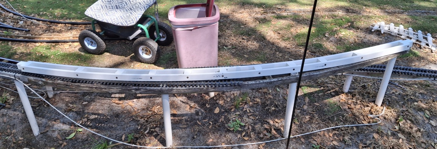
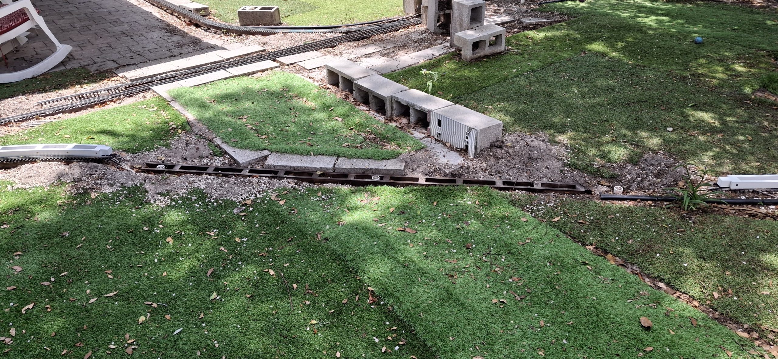
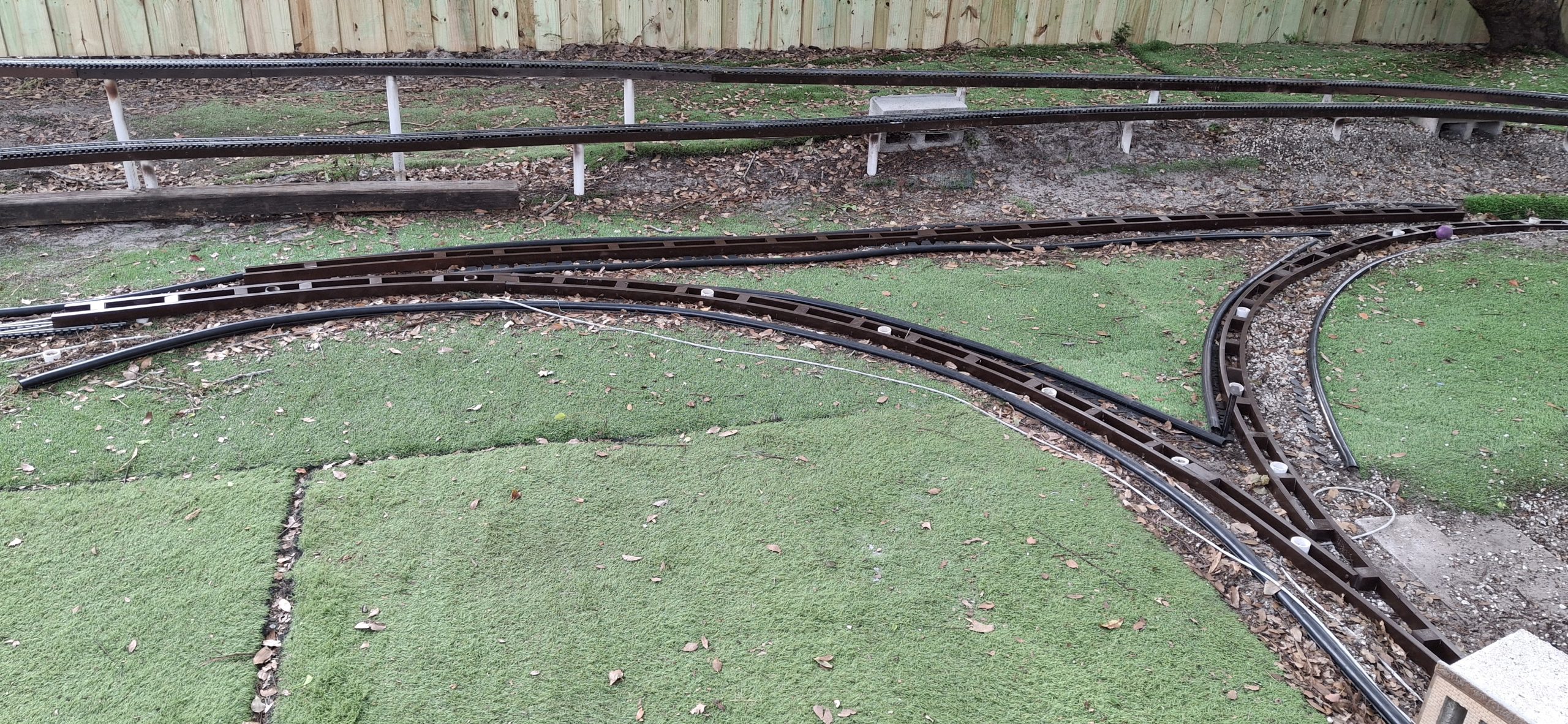
This is taking much longer than expected, but continued improvement each weekend brings us closer to our goal of running trains. We left off with all the elevated sections painted and installed. In addition, the downtown mainline, station siding, and long siding are installed. Those took longer because those stretches are on the ground and more rotted stringers needed dug out first.
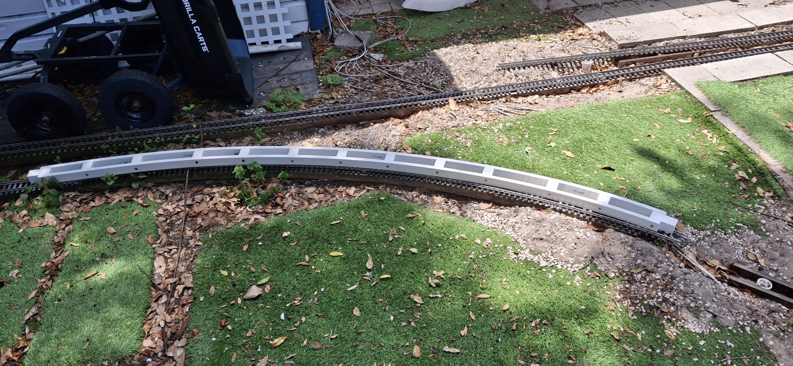
The track is installed as well, with the one exception of the stretch where the bridges will go. For now it’s just a straight elevated section waiting for track and bridges. Originally the thought was the approaches would be of trestle construction, but now I’m leaning toward laced steel girder supports and plate girder bridges. That can wait until later. We can run trains without any of it.
Fixing The Wye
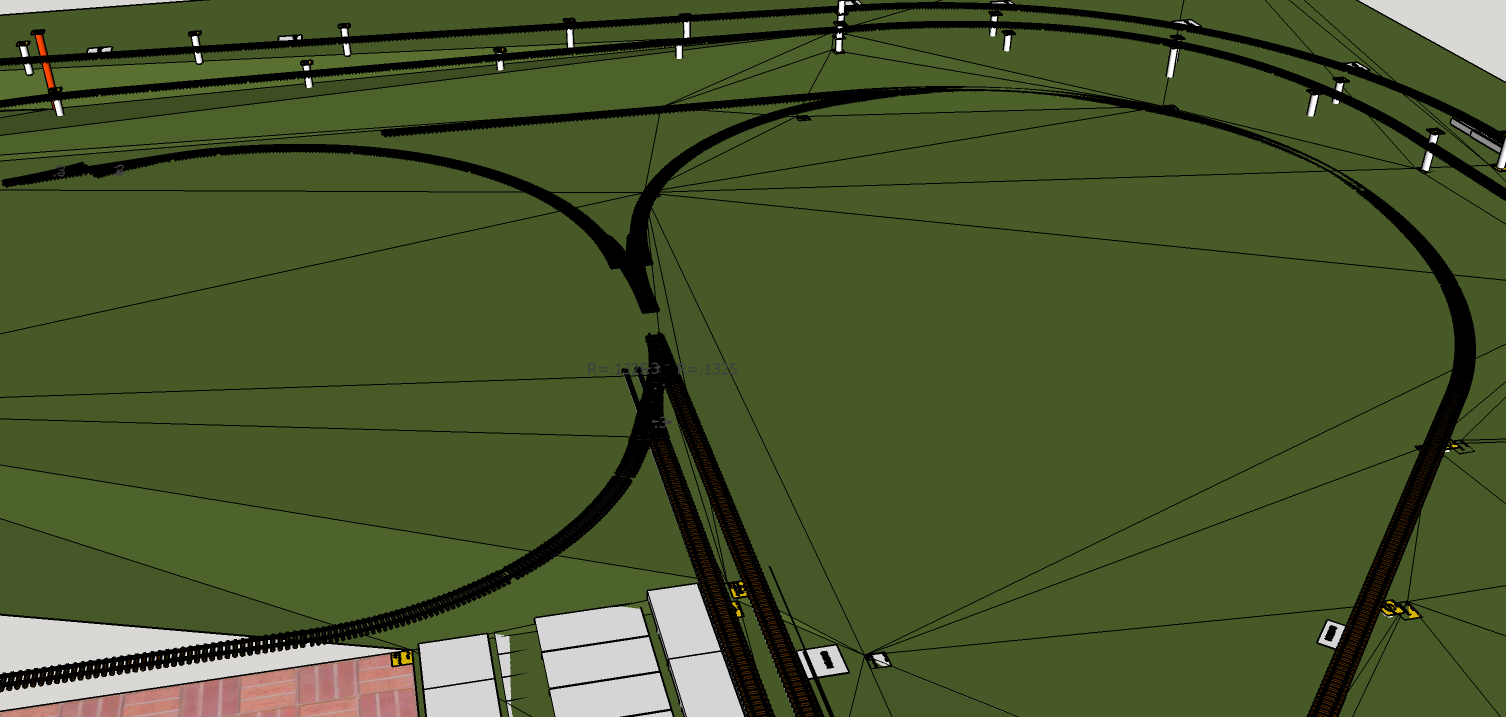
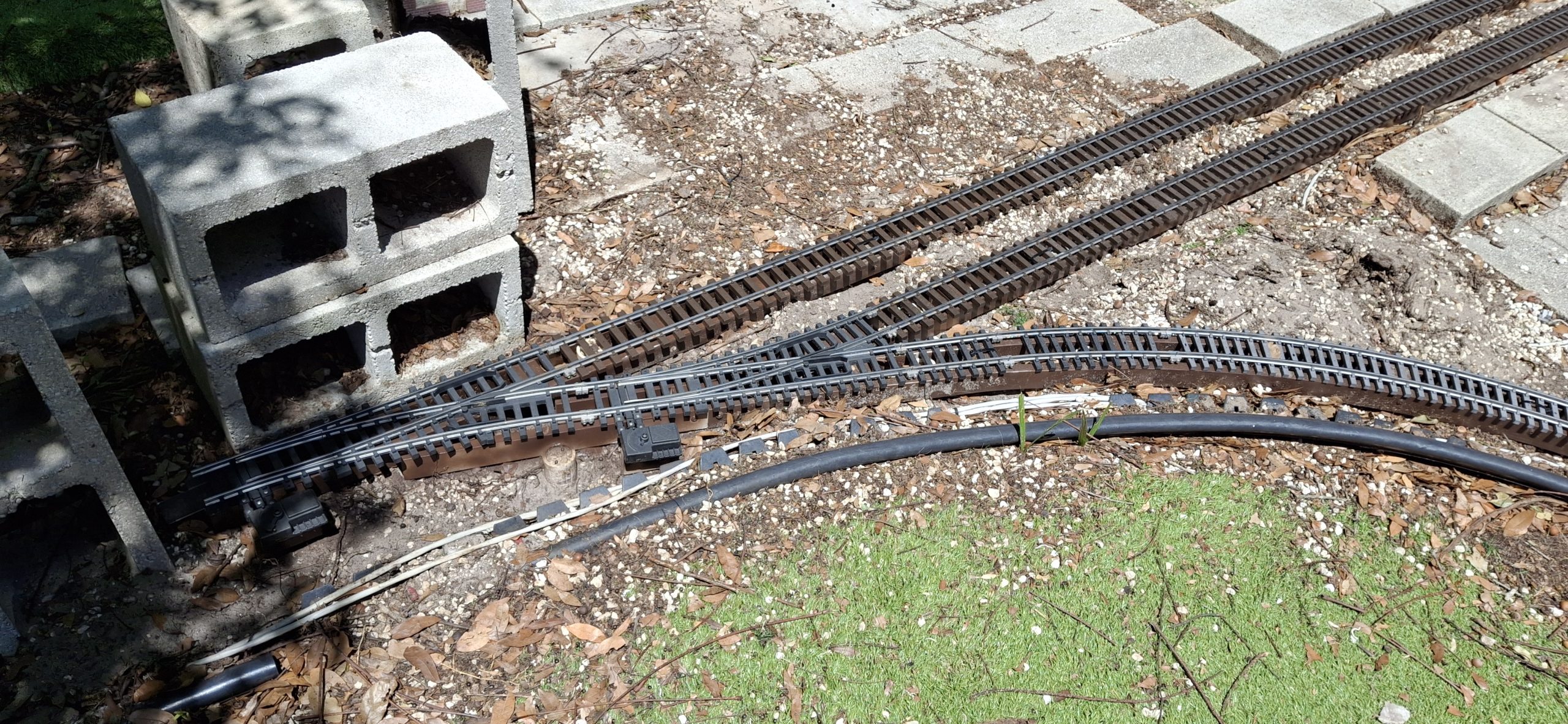
Hadn’t really planned on doing anything more than what’s necessary to replace the 20′ diameter track section and wye switch with 14′ diameter sections. Essentially we want to “hardwire” the Downtown loop to return to the mainline, reducing the layout to its original “dogbone” roots with two loops, one Downtown, and one over the deck.
The thinking was maybe we’d restore the wye in the future. Well, the future is now. What prompted this change? It all started with having to replace the stringers on the 20′ diameter section of the Downtown loop. It ended with finding the old homemade #5 switch design and bringing it out of mothballs. Somewhere in between we discovered that fixing the wye would be easier than not.
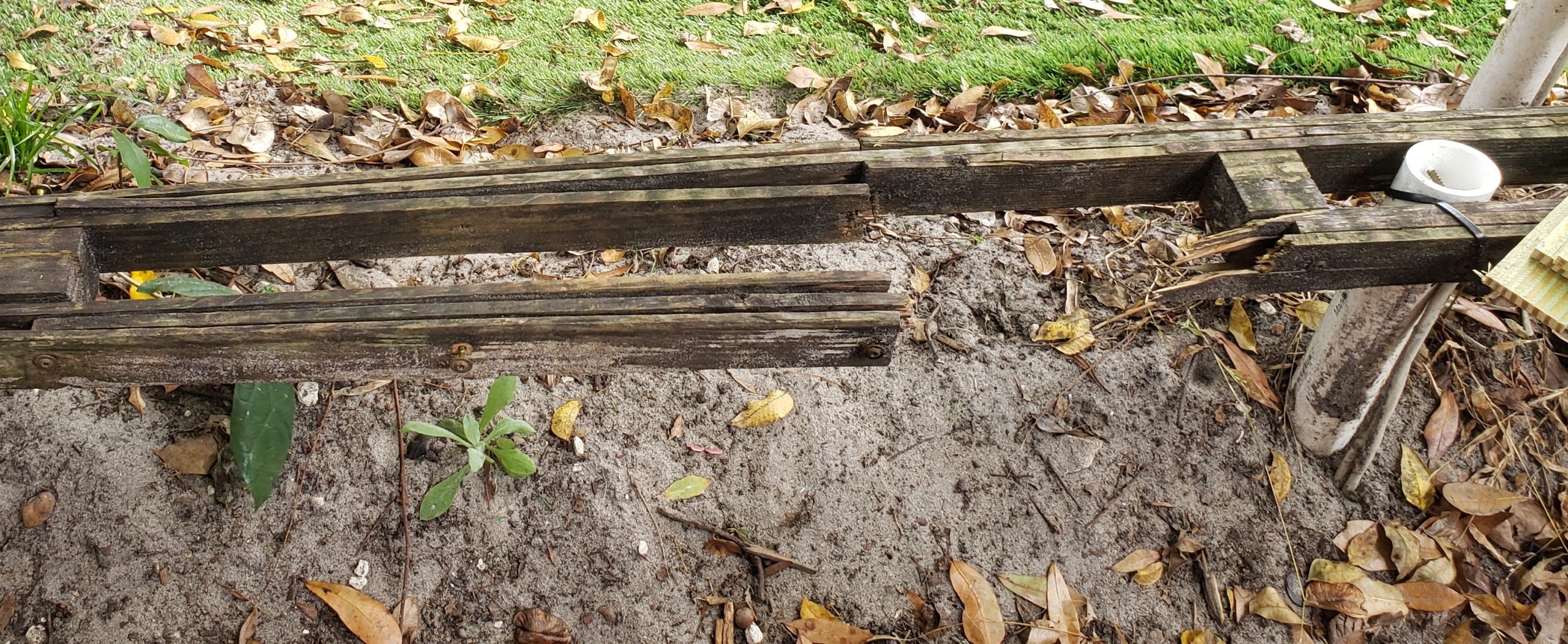
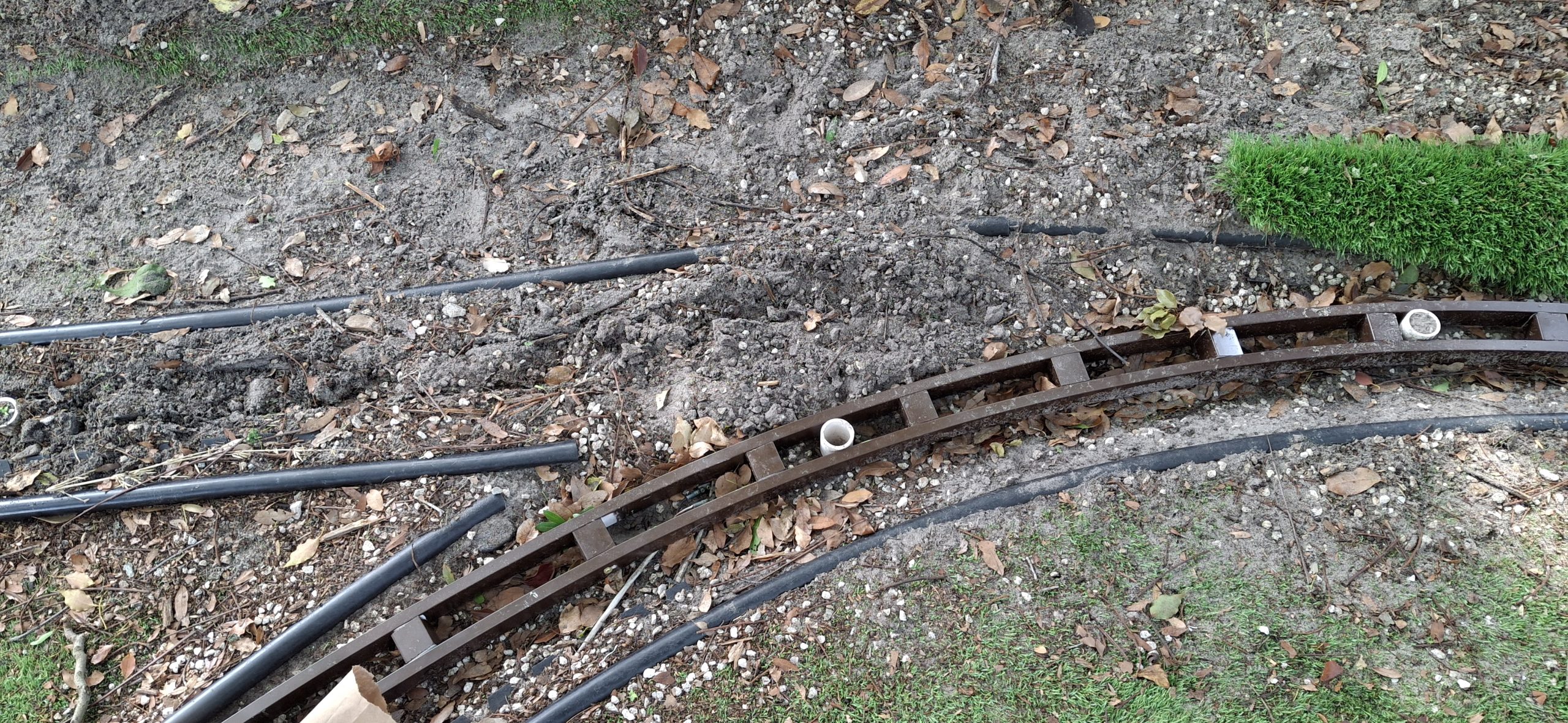
Since the track was still in place over the 20′ diameter section, the assumption was the stringer beneath was still in good shape. That was a poor assumption. Oh well, we’ll just make another 20′ diameter replacement while we’re at it. Slowly but surely that stretched into the next 14′ diameter section, then the next, and another after that.
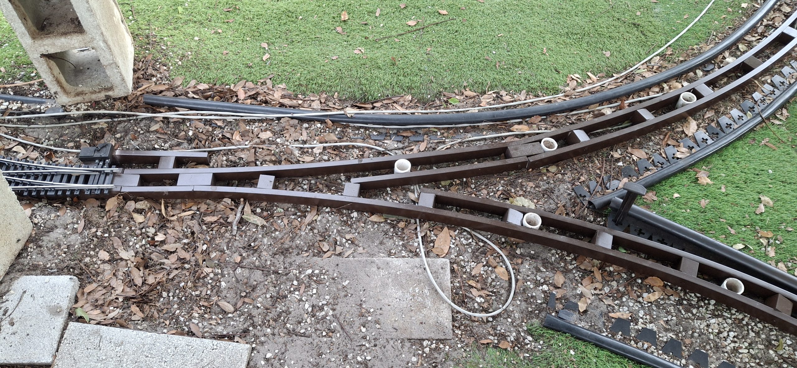
Working toward the wye switch it became apparent all the wye stringers were rotted and need removed. Replacing each new section of the 14′ diameter stringers, it soon became apparent the posts weren’t arranged in a 14′ circle either. Turns out we’ll need another 14′ diameter stringer to reach the wye switch as well, once the remaining rotted stringers are removed that is.
If It Doesn’t Fit, Force It…
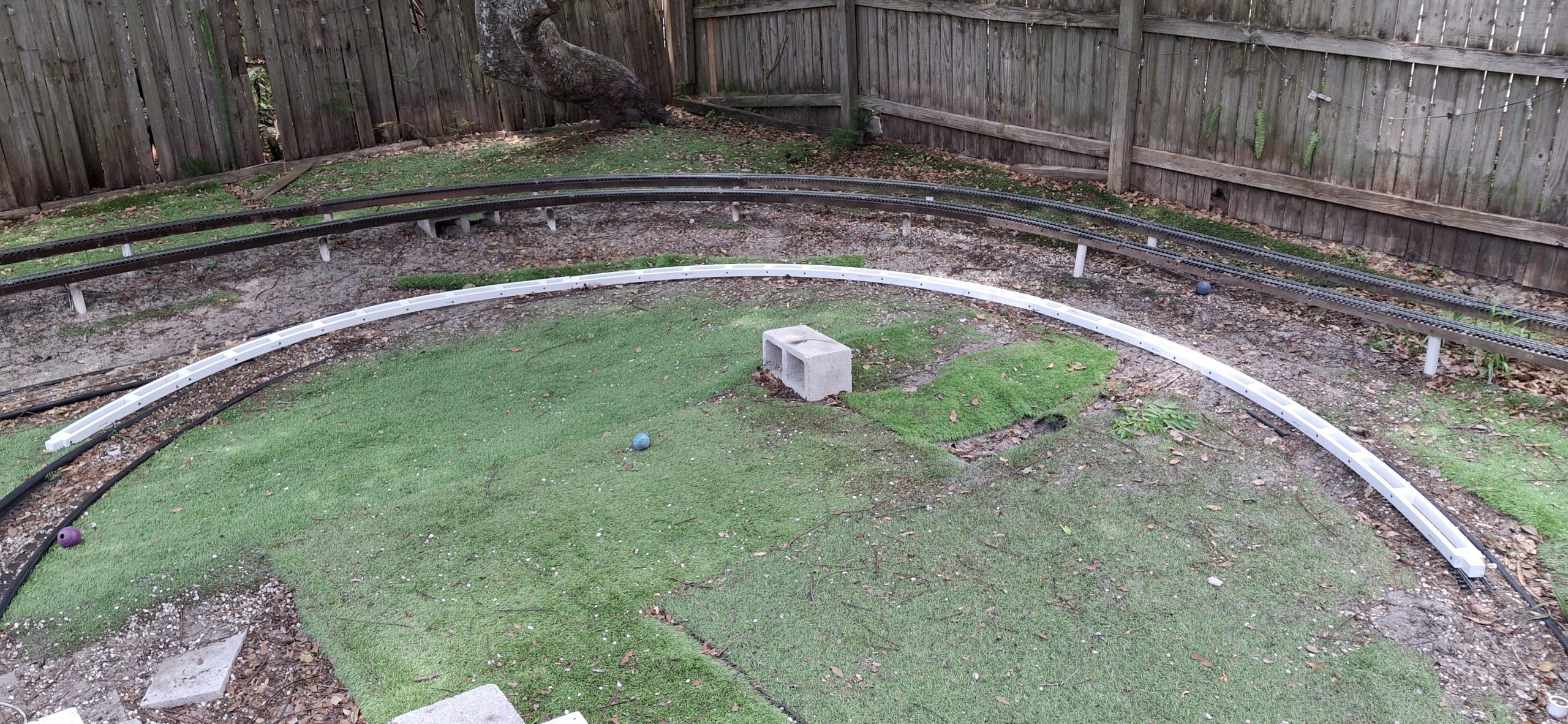
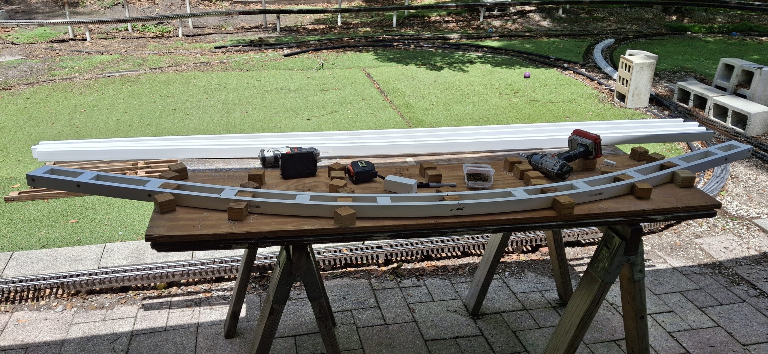
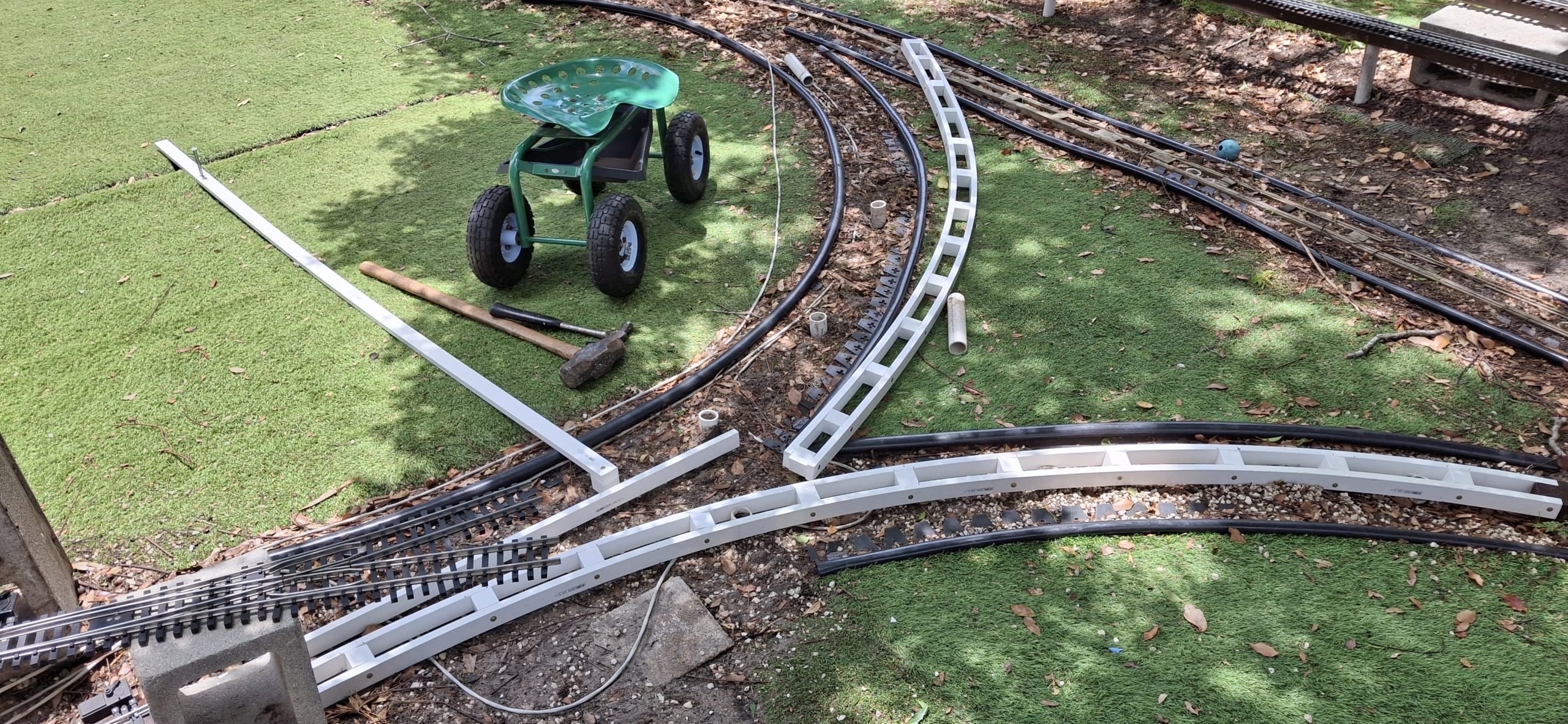
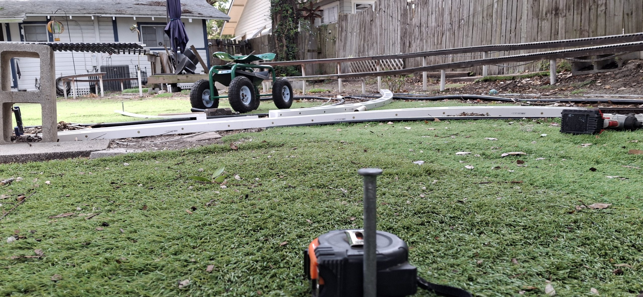
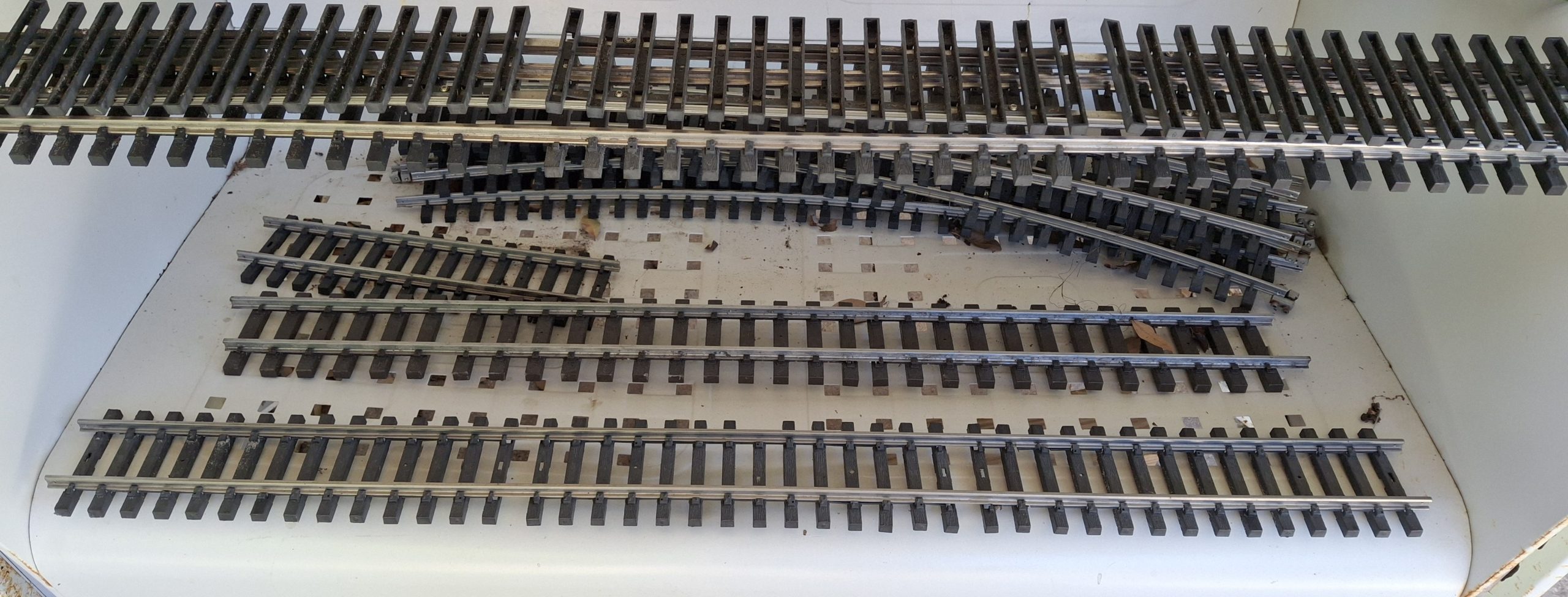
Force fitting those 14′ diameter legs of the wye may have made sense at the time, but now leaving them that way is more trouble than making it right. Time to break out that wye switch and take some measurements. We’re trying to locate the centers of those 14′ diameter circles, one on each side, based on the true geometry of the wye switch. But we’ll need something straight at least 7′ long.
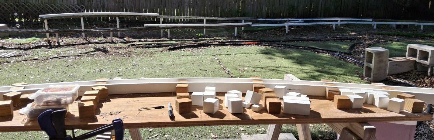
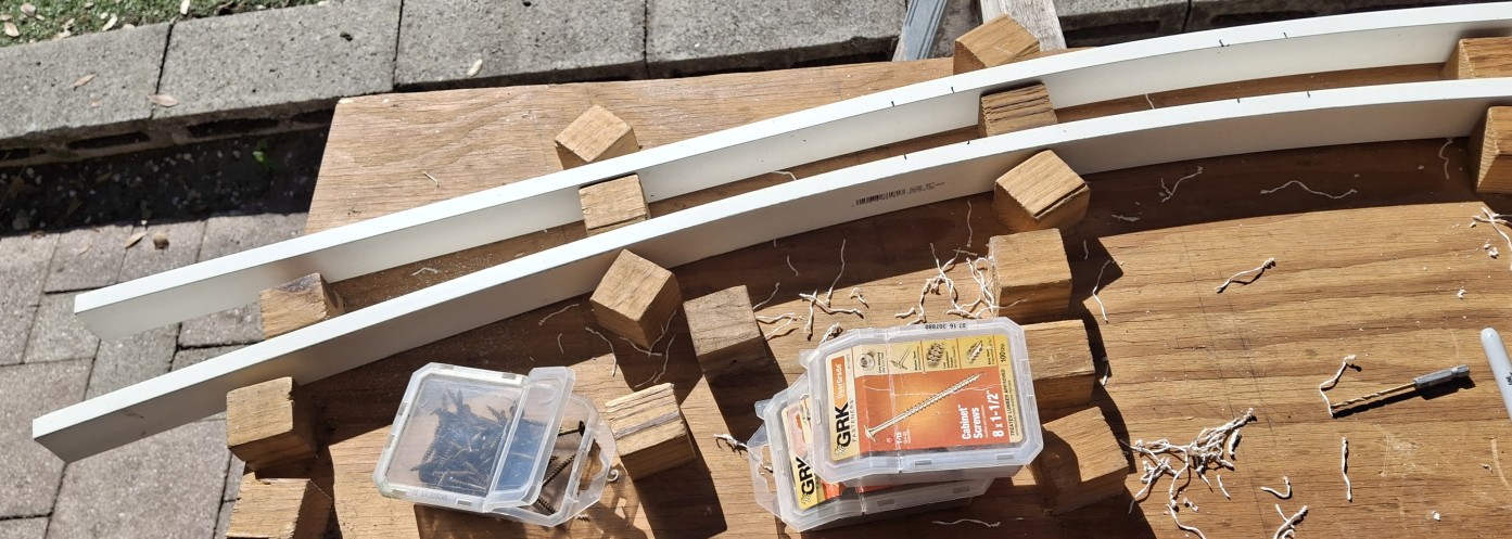
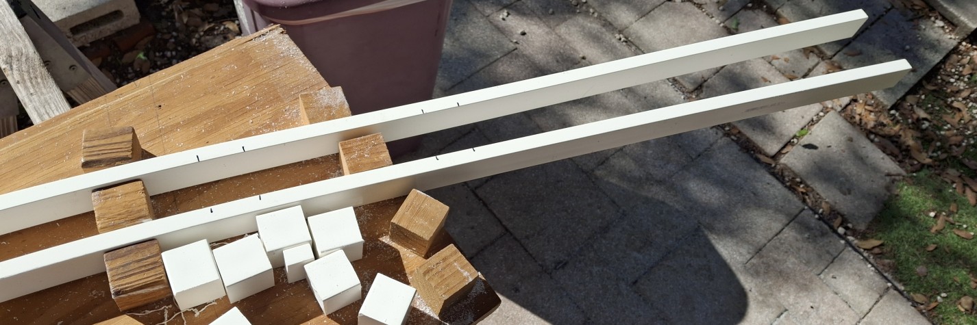
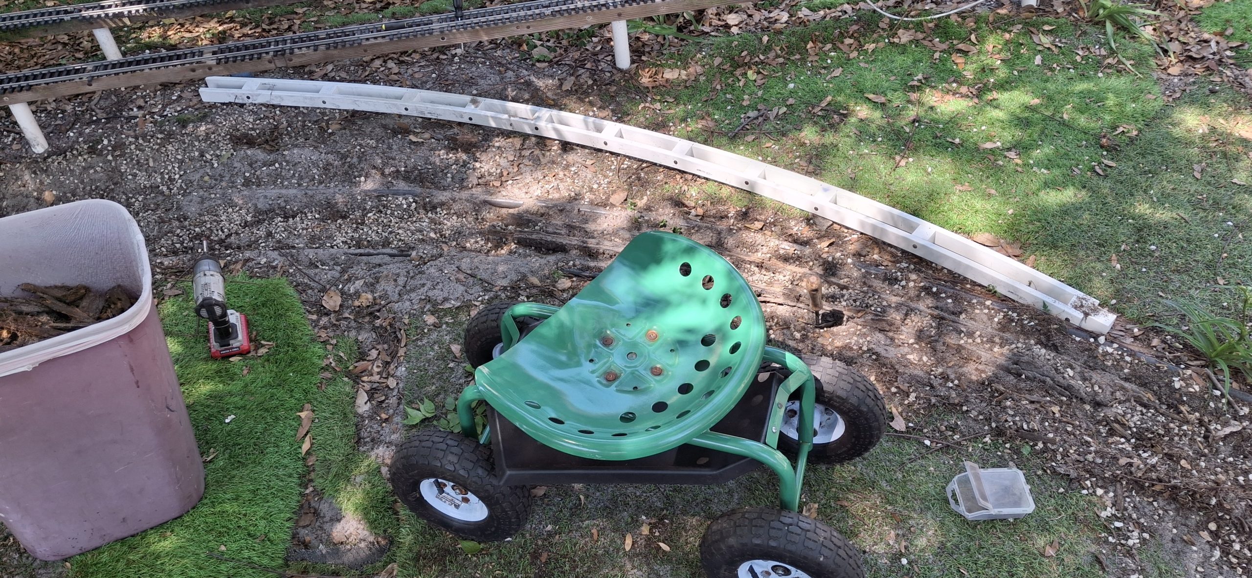
Hmmm…. What do we have that is both long enough and straight enough? We have a whole stack of 8′ long PVC 1x2s not yet assembled into new stringers. One of those would certainly fit the bill. Marking out the centerline on the turf with a sharpie is close enough, but reminds me of previous opportunities lost without a more permanent center marker.
There has to be a better way to do this. Time to find one of those spare “turf nails”. Found a bunch of them in one of the drawers in the toolbox, and two different sizes no less! The idea is to “pin” the center with one of the larger turf nails. Beyond that, by attaching one of those 1⅝” spacers to one end of the 1×2 and drilling a hole to fit the nail marking the center at the other end, we have an accurate compass.
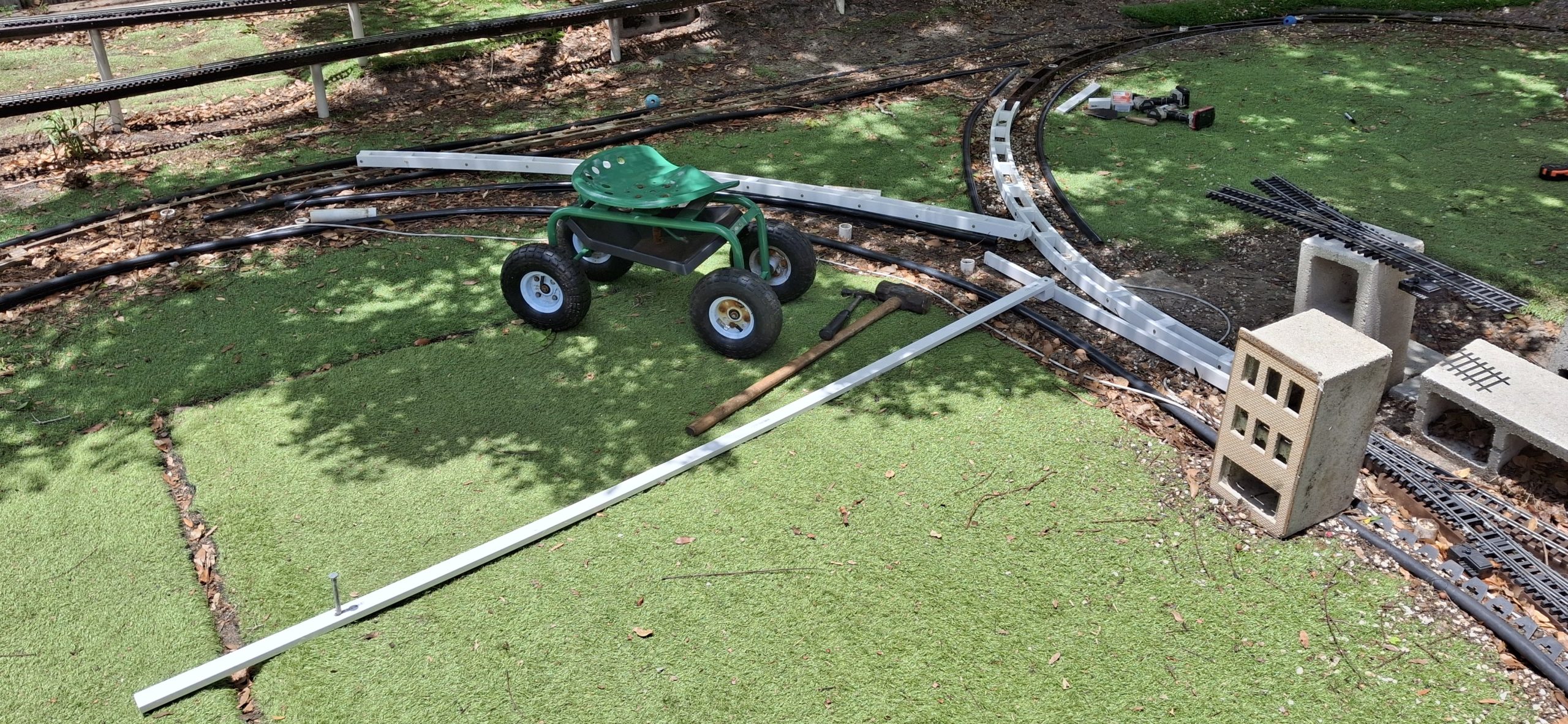
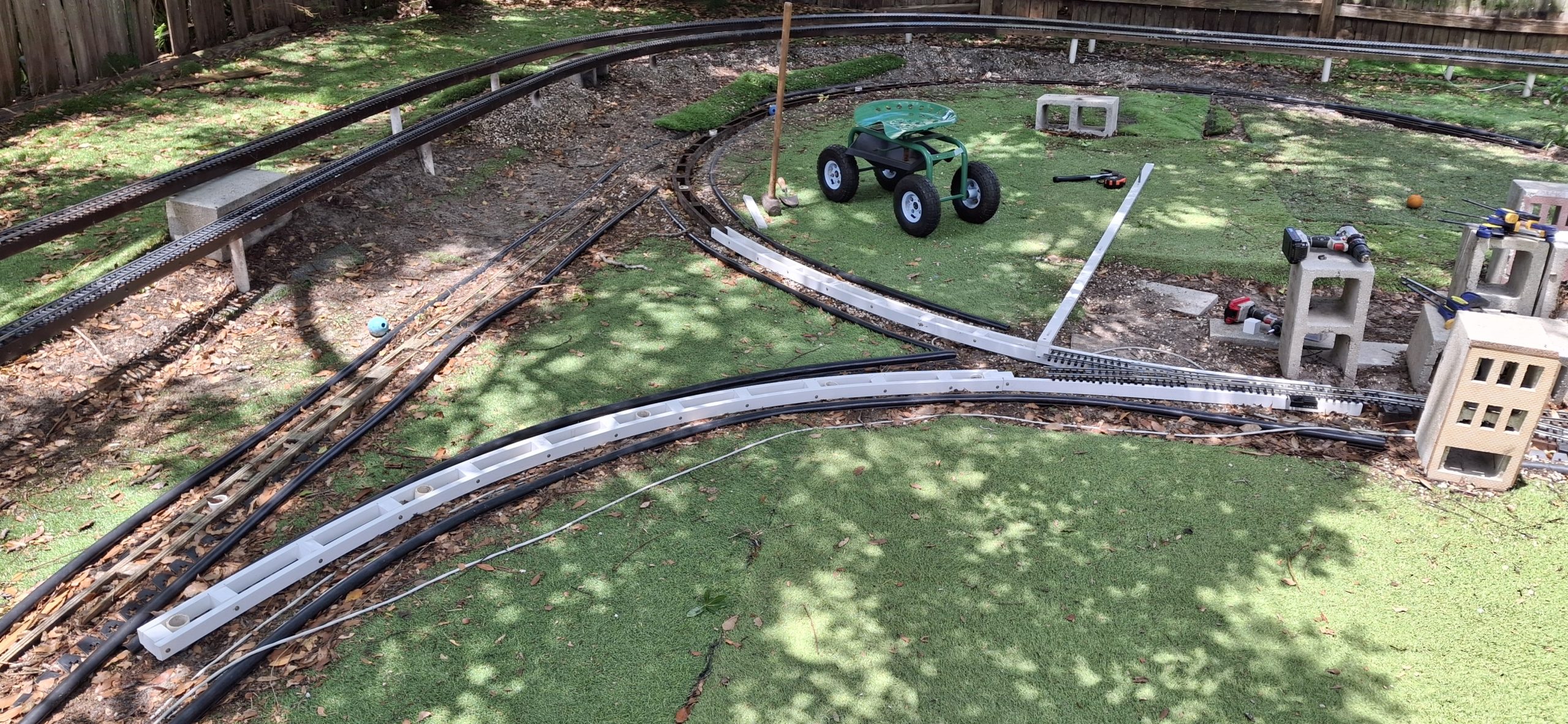
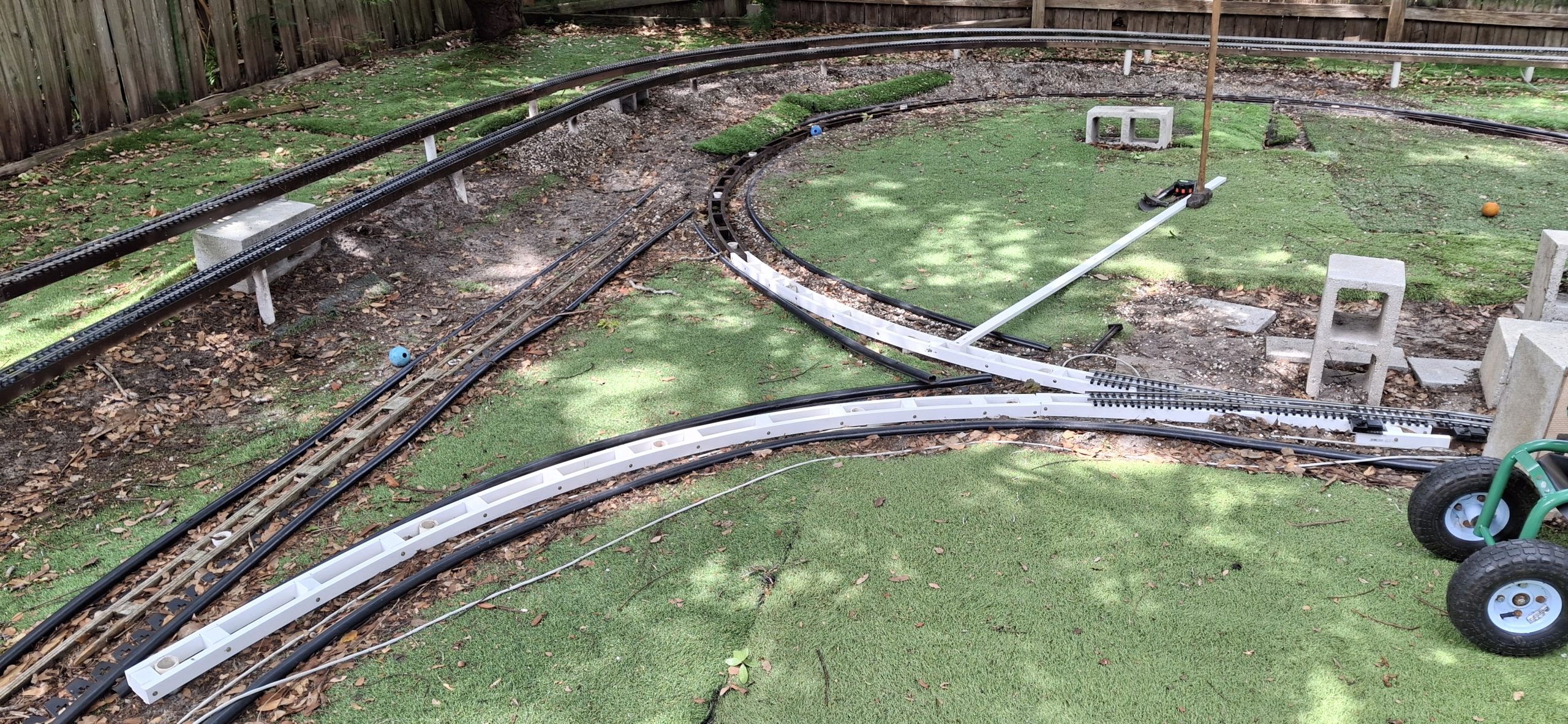
With our new PVC “compass”, we can “sweep” a 14′ diameter circle, holding the stringers in place with that spacer. It fits nicely between the two sides of the stringer and holds it in place while confidently driving a post into the correct location. That involves pulling out the existing incorrectly located posts with a set of Kleins then accurately smashing them back in with the sledge hammer.
All Kinds Of Wrong
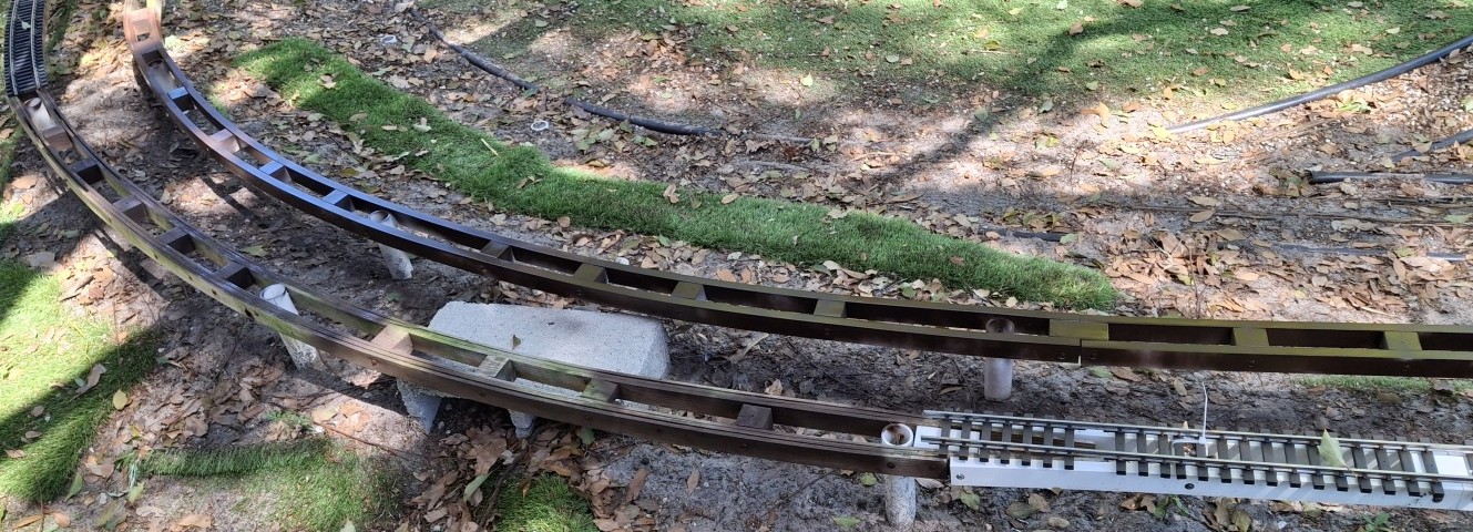
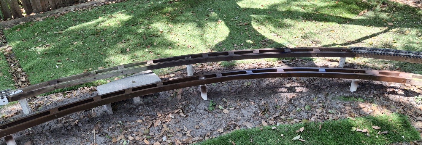
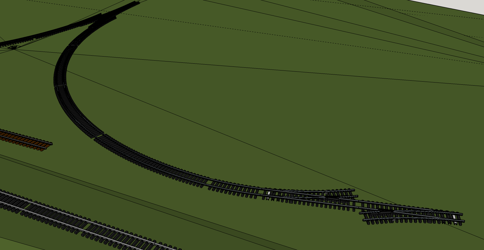
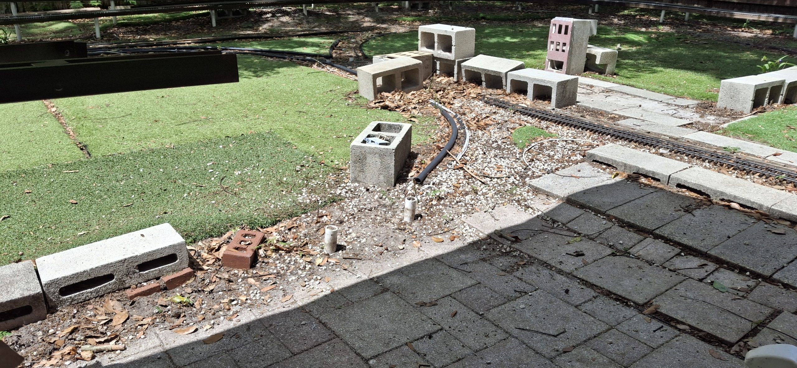
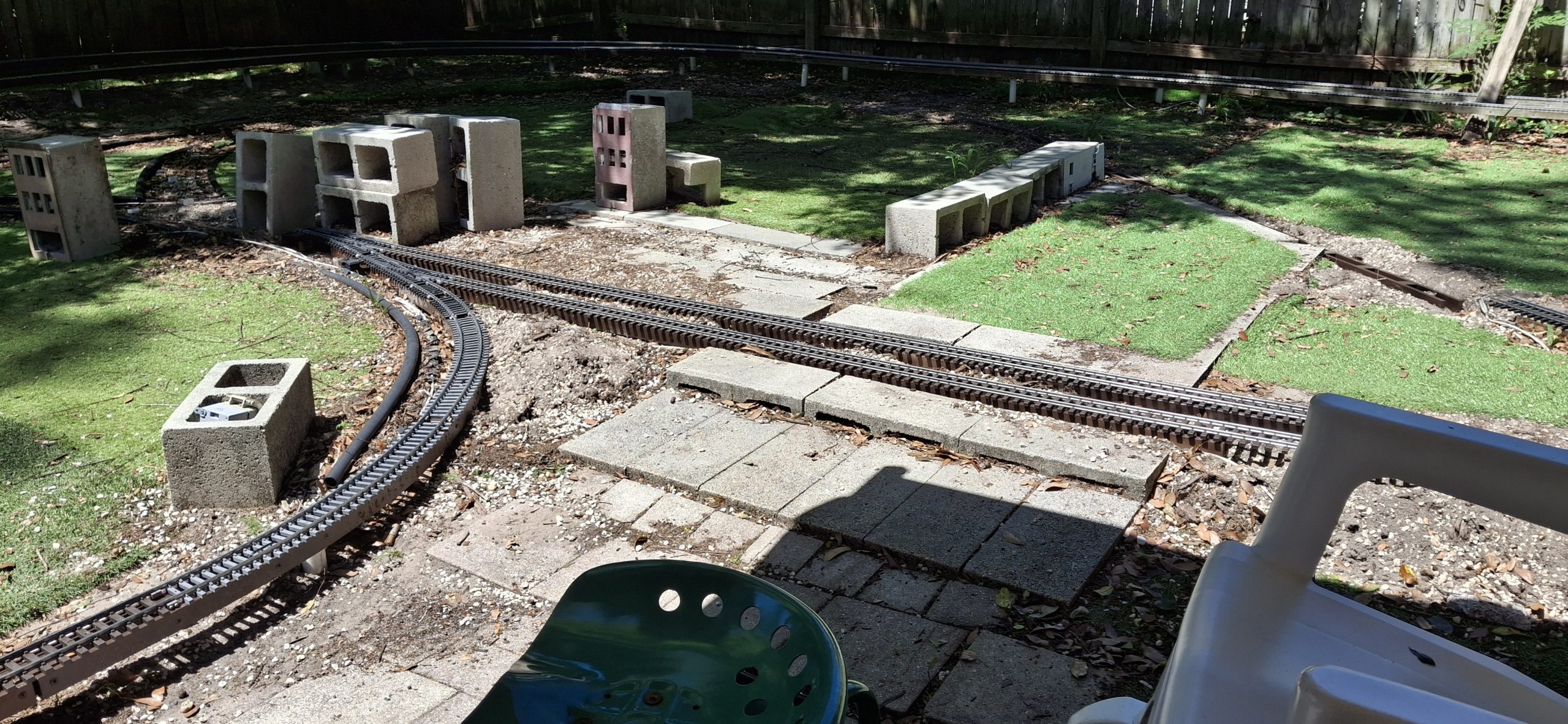
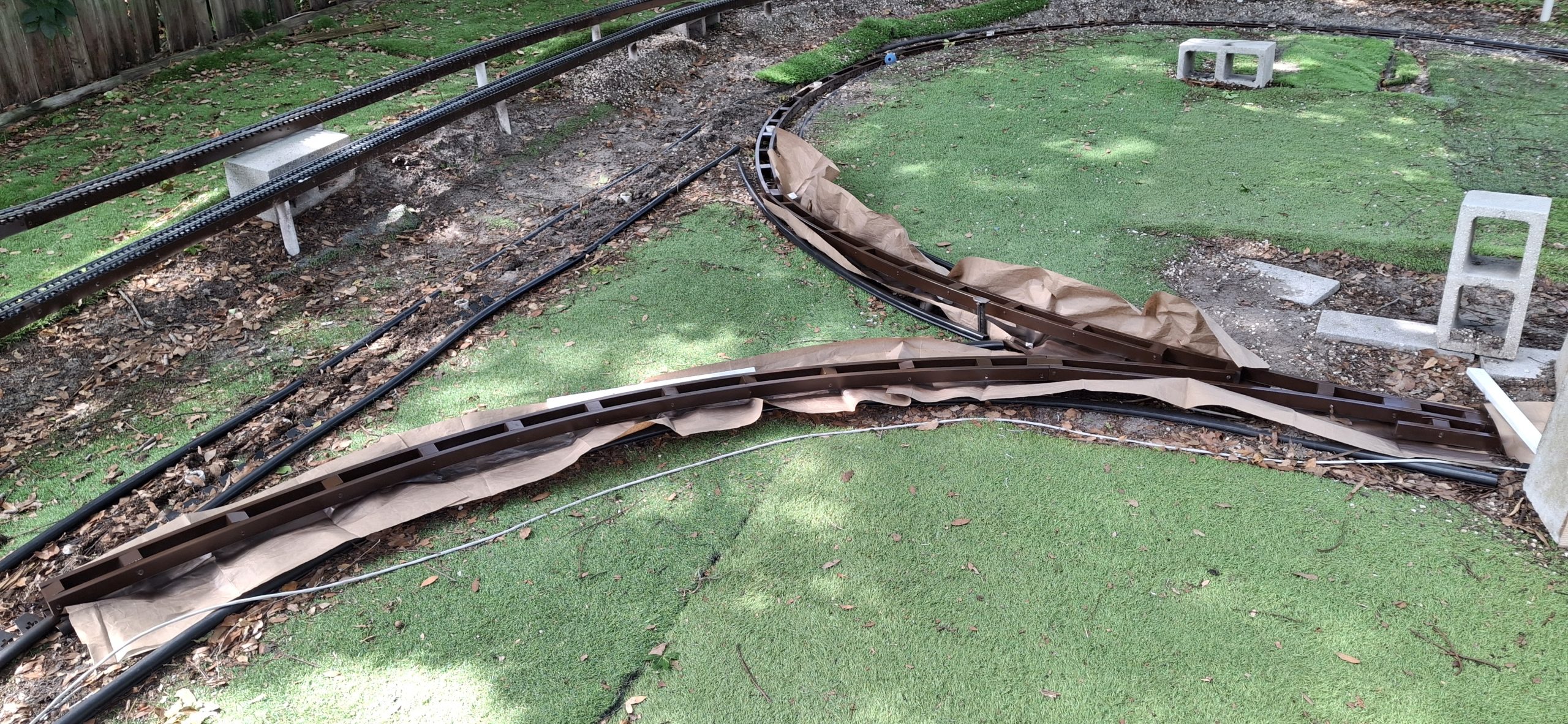
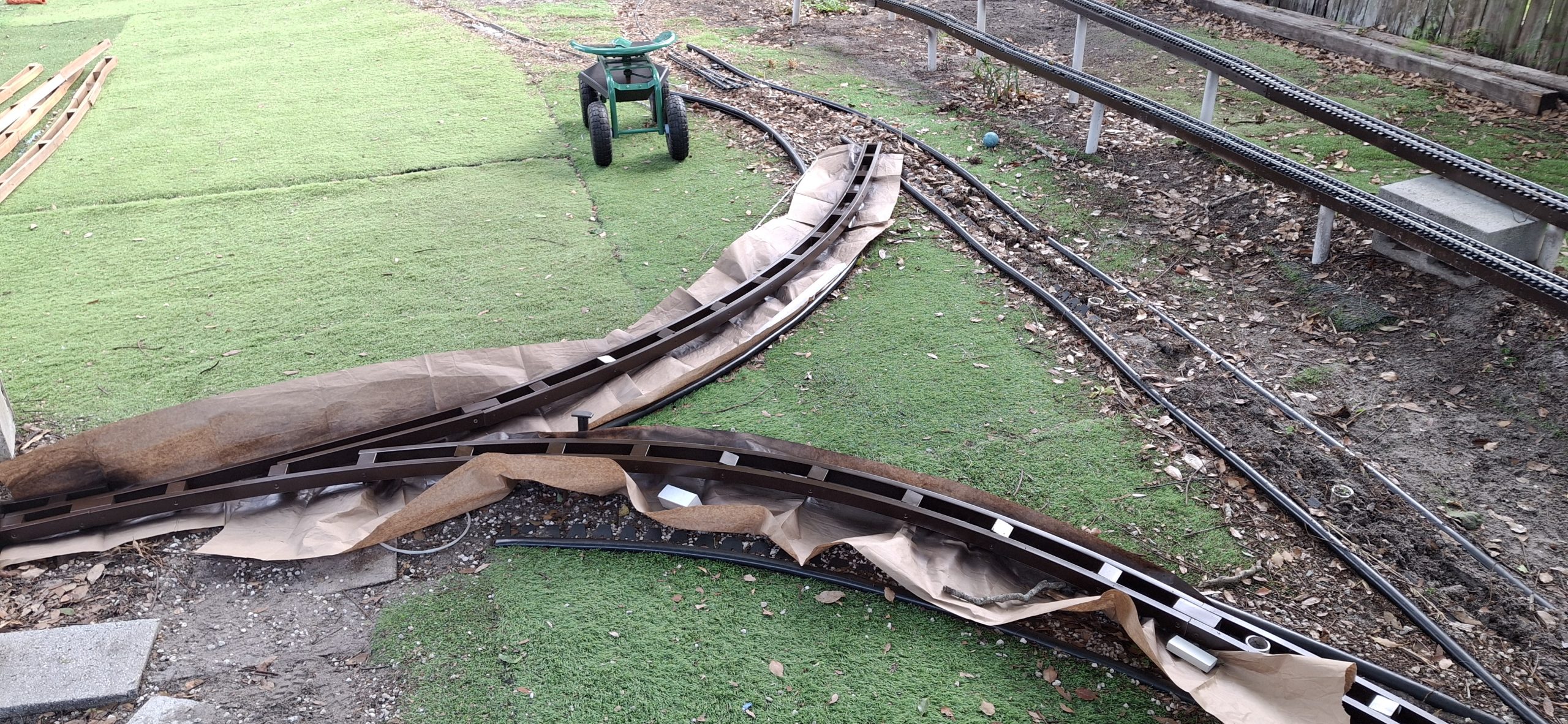
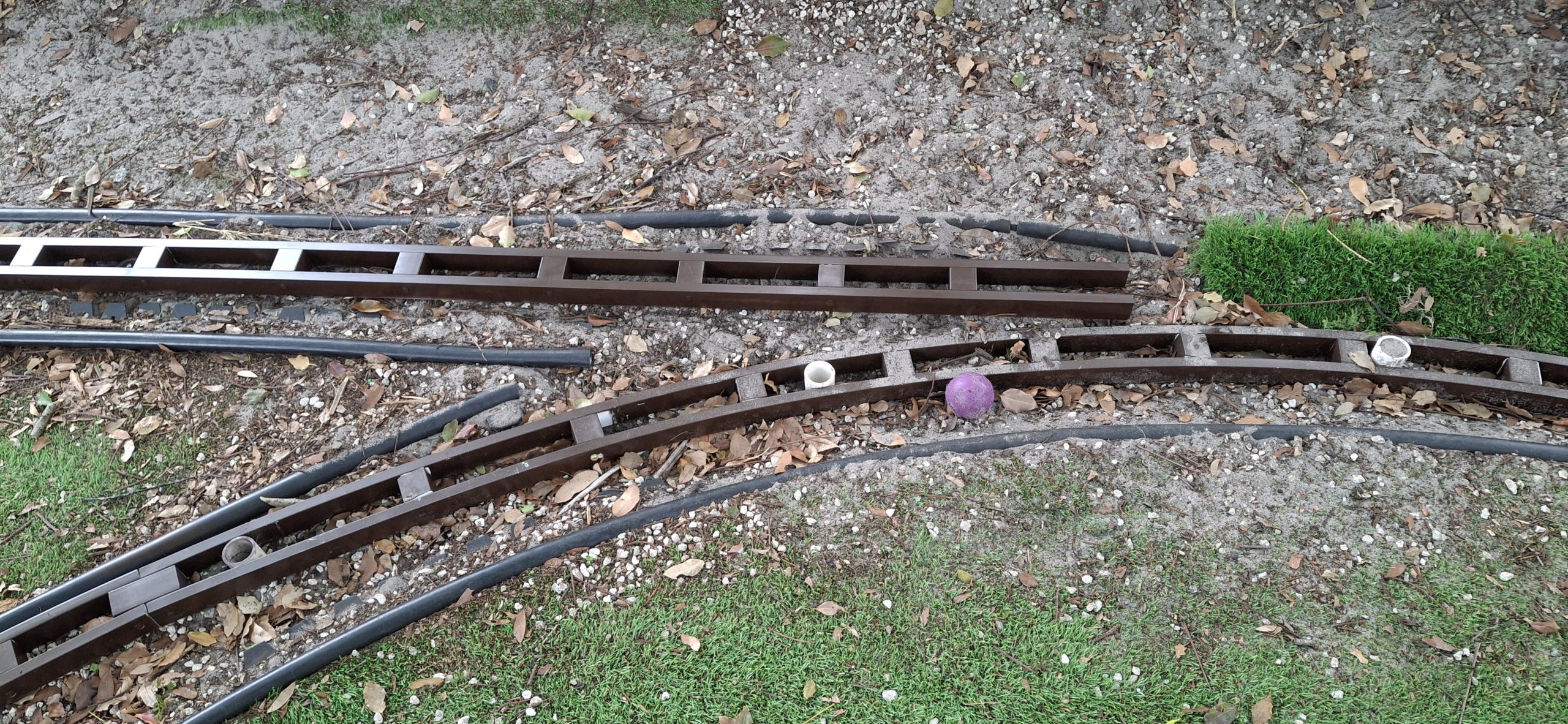
As helpful as our new PVC compass is for laying out the curved stringers, it also excels at pointing out all the mistakes in our original geometry. Both legs of the wye were off by more than twice the width of the track! No wonder the track refused to cooperate and go where it was supposed to without a fight. All kinds of wrong.
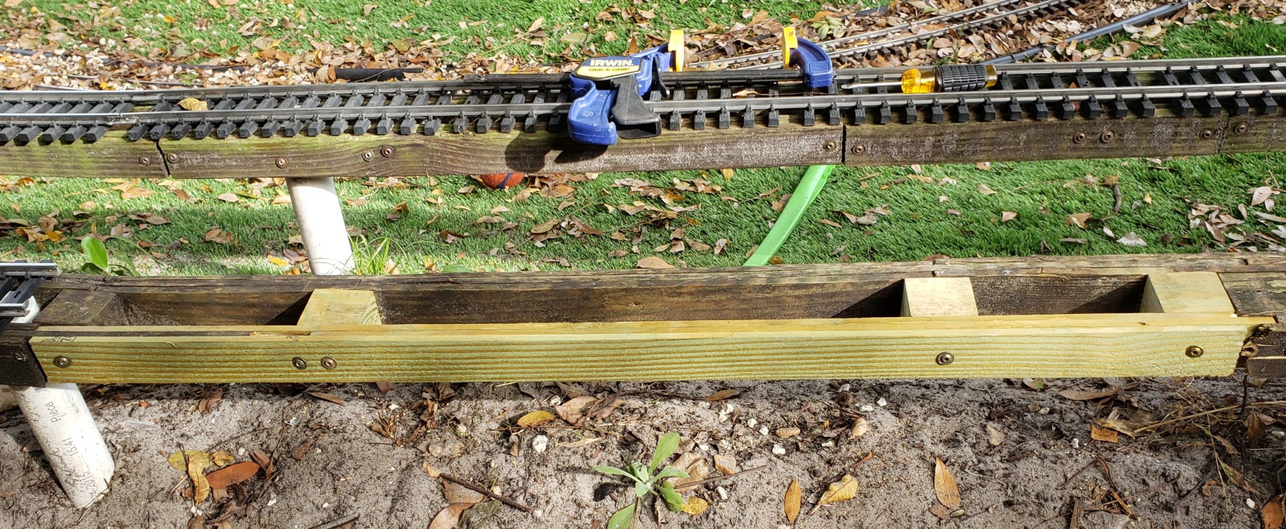
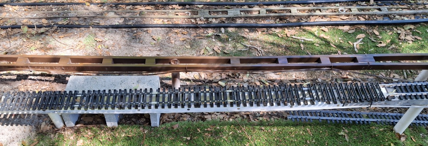
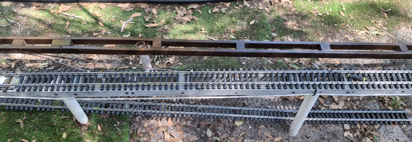
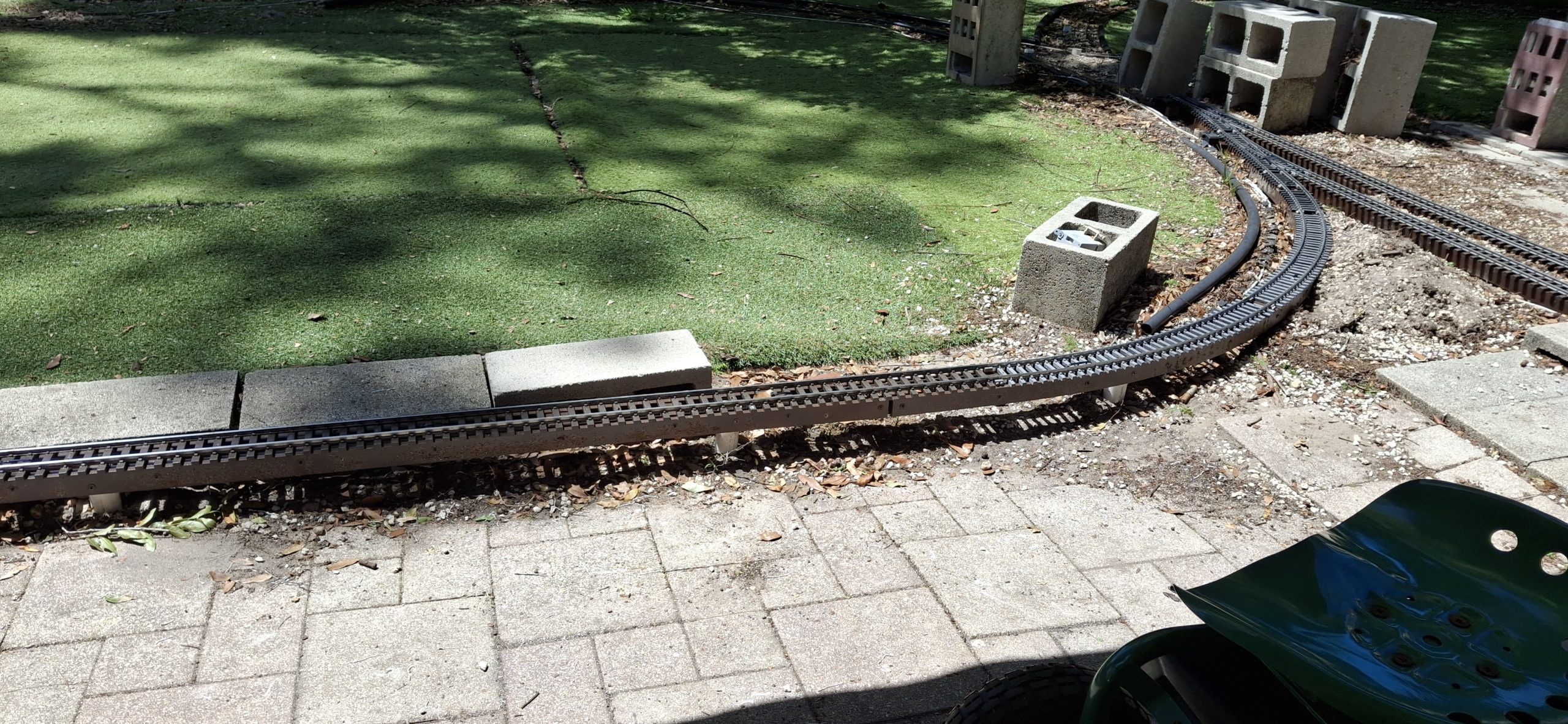
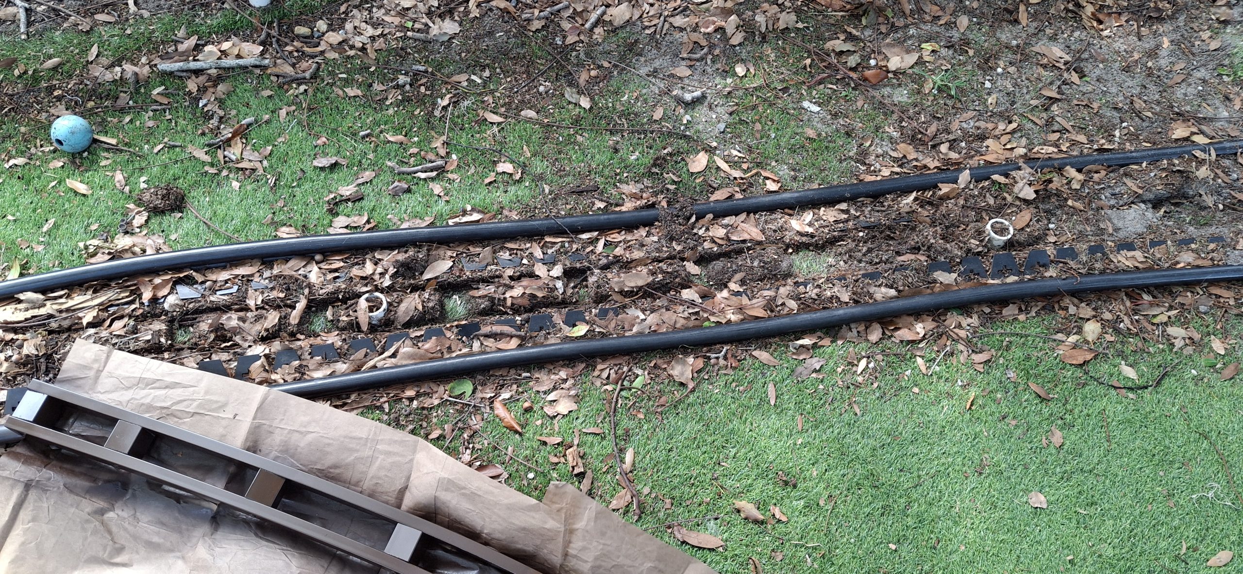
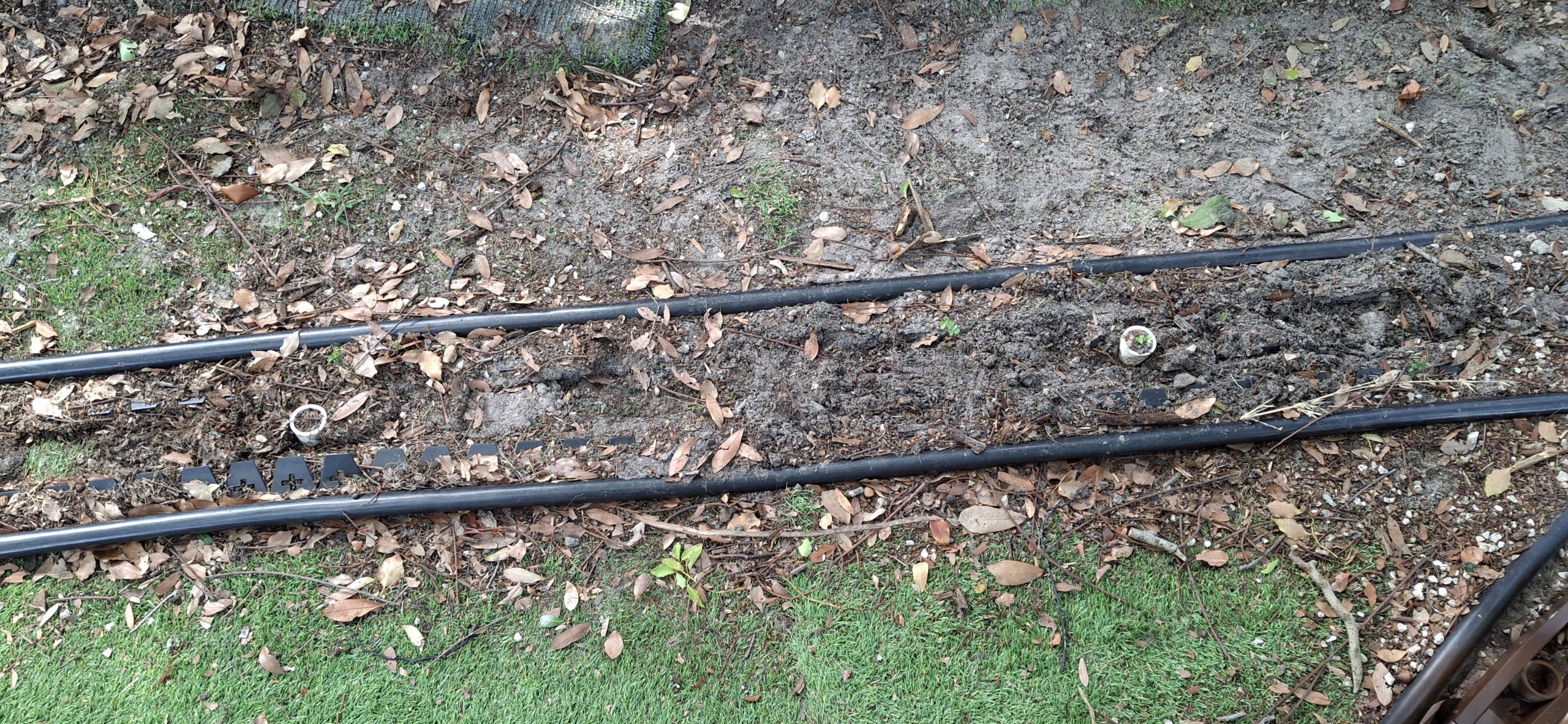
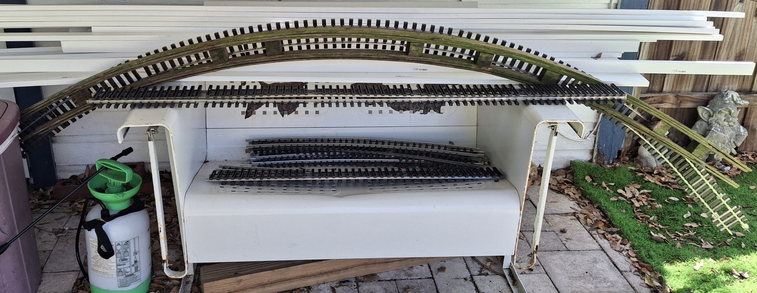
On the North leg of the wye, the closer it gets to where we need that curved switch, the more the radius relaxes into a wider curve. On the South leg, the closer it gets to those toe-to-toe switches, the tighter the radius gets! If you look closely at the pictures, you’ll see how far off the black edging is now. Good thing we’re using flex track for both curved legs!
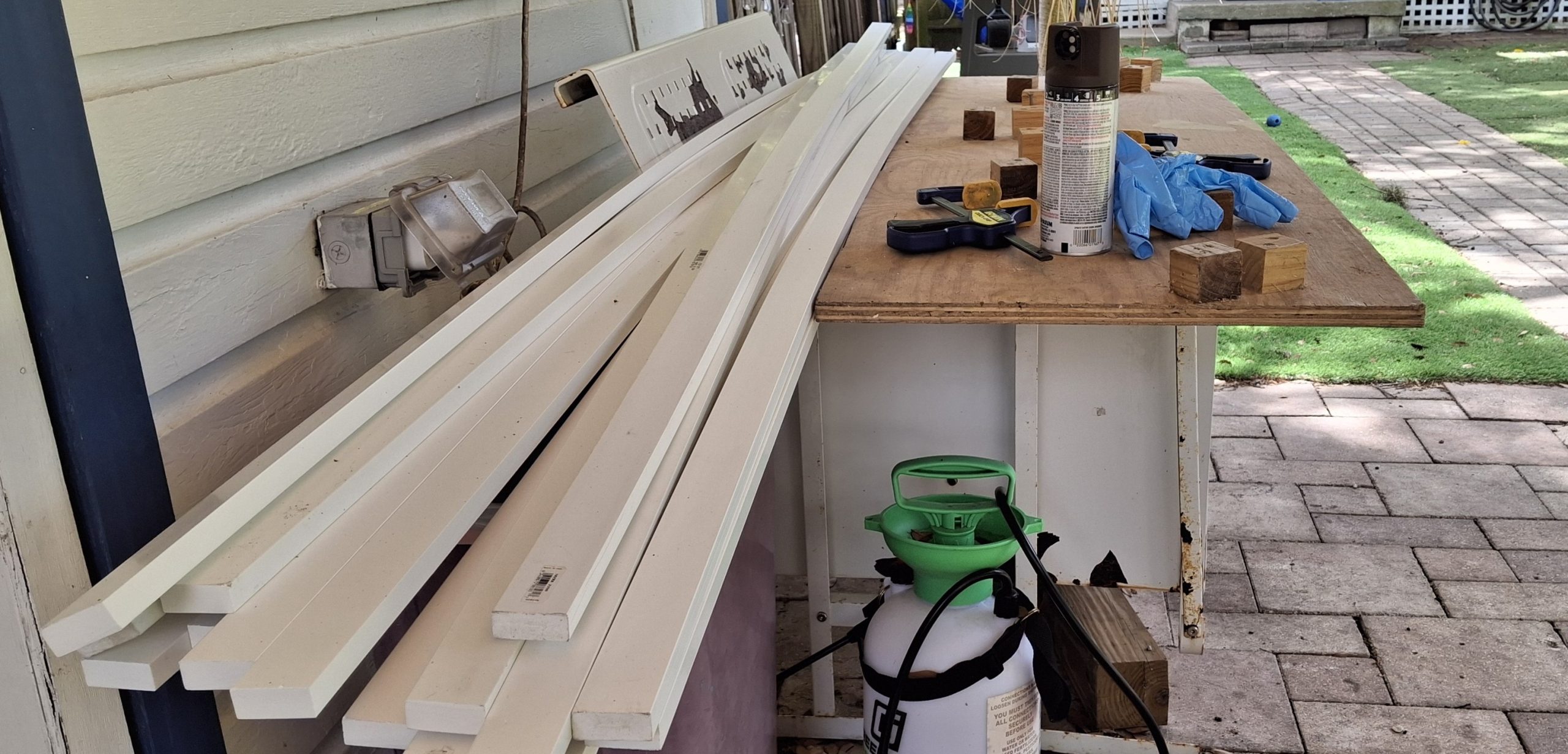
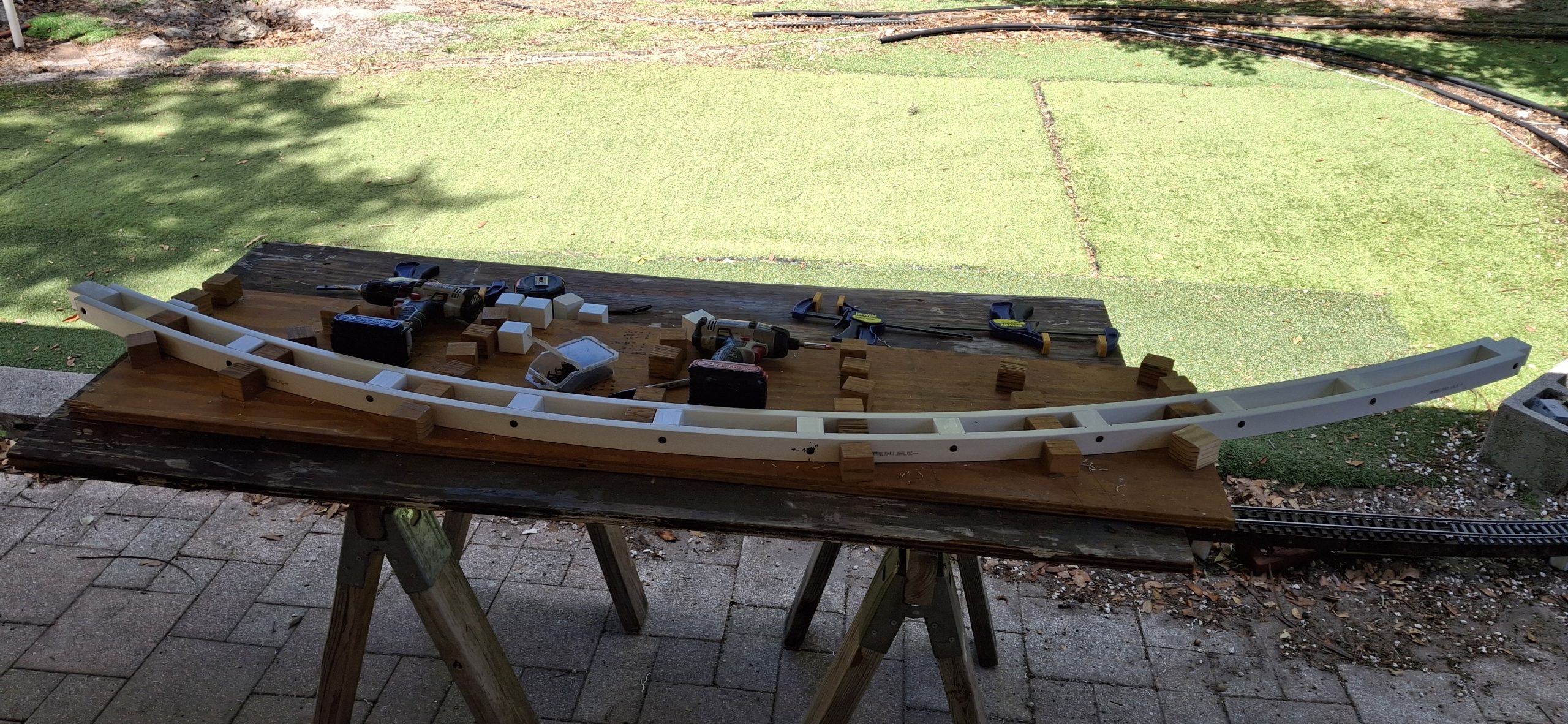
It may take some time with the rail bender to finesse the wonky curved flex tracks to fit properly, but it’s totally worth the effort. Both stringers now follow a smooth curve that fits the desired geometry. I just wish I’d painted those stringers before fastening them together! Nothing some strategically placed masking paper won’t handle.
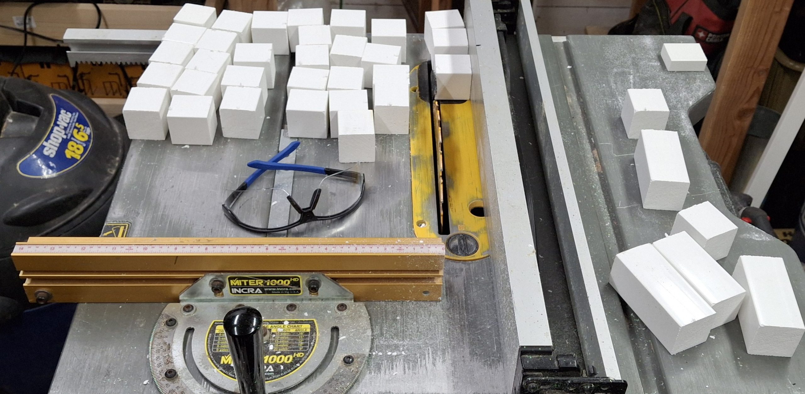
So kind of a funny aside. A while back I asked Nick to pick up a couple cans of brown spray paint for me from Lowe’s. He got me two of the fancy adjustable nozzle Krylon brown and two of the 2X espresso color. I used those up weeks ago. The next time I was there, Lowe’s was out of the 2X espresso I wanted, so I got three with the fancy nozzle in dark brown. They’re also gone now.
Last time there I bought all the 2X espresso they had, the three left on the shelf and the remaining case of six I had to have an associate fetch from the rack high above using the huge rolling ladder thingy. After painting those wye stringers, I’m down to my last four cans! But I’m getting ahead of myself.
The only reason we’re talking about painting in the first place is because of protecting the PVC from Ultra-violet (UV) radiation, which breaks the bonds in the flexible long chain polymers, making it more and more brittle over time. Paint is a means of protecting the PVC from the UV degradation of baking in the hot Florida sun. An added bonus is it looks much better than bright white!
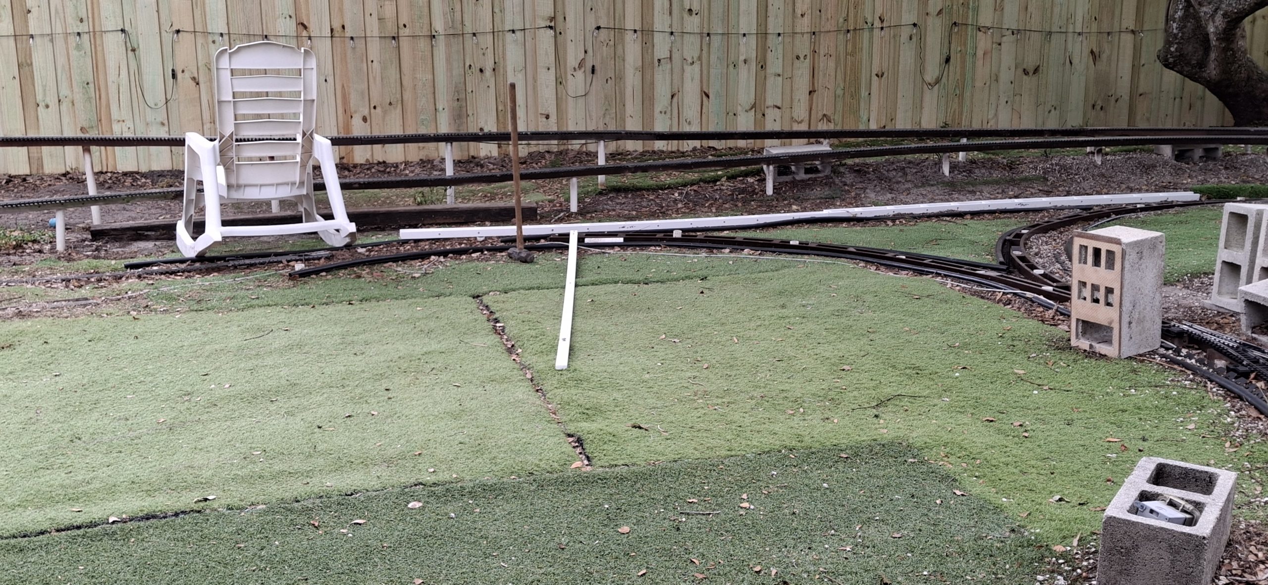
Time To Take A Fence Break
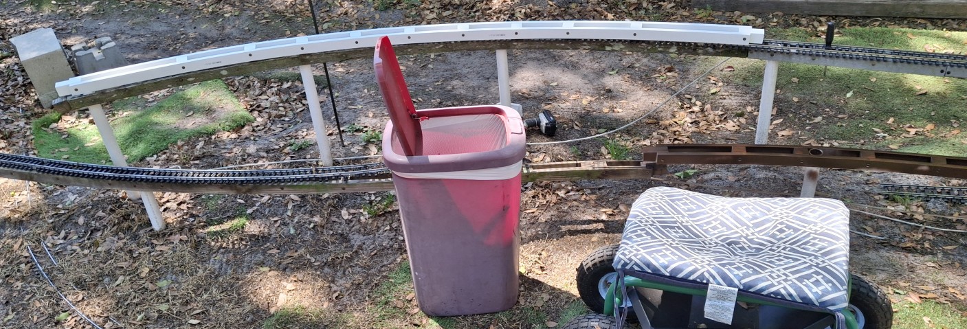
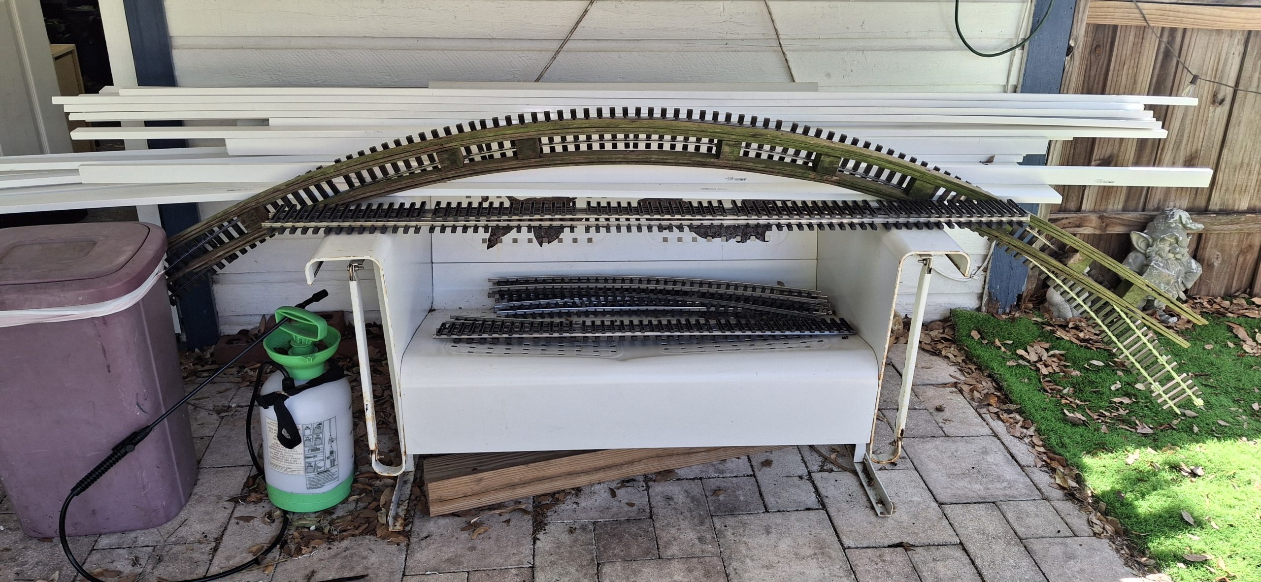
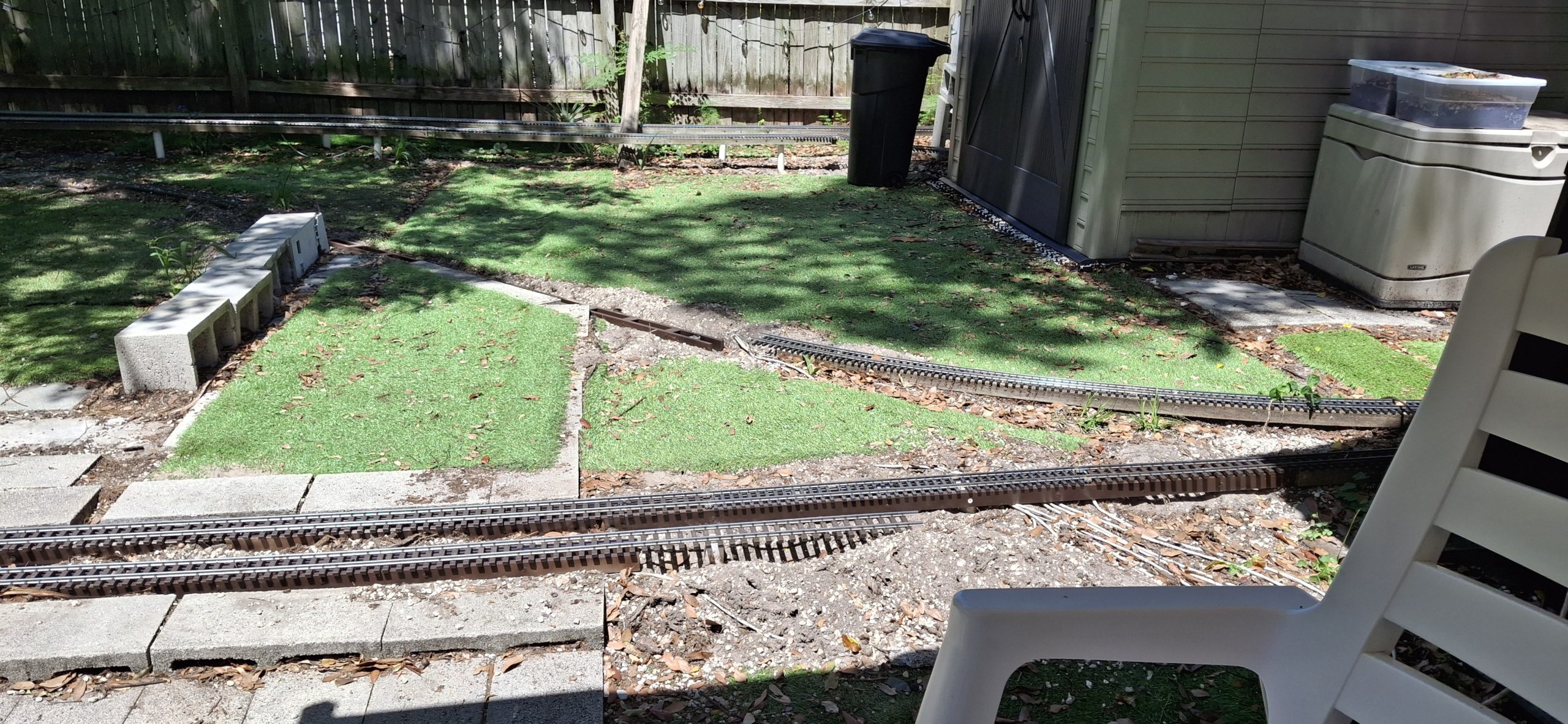
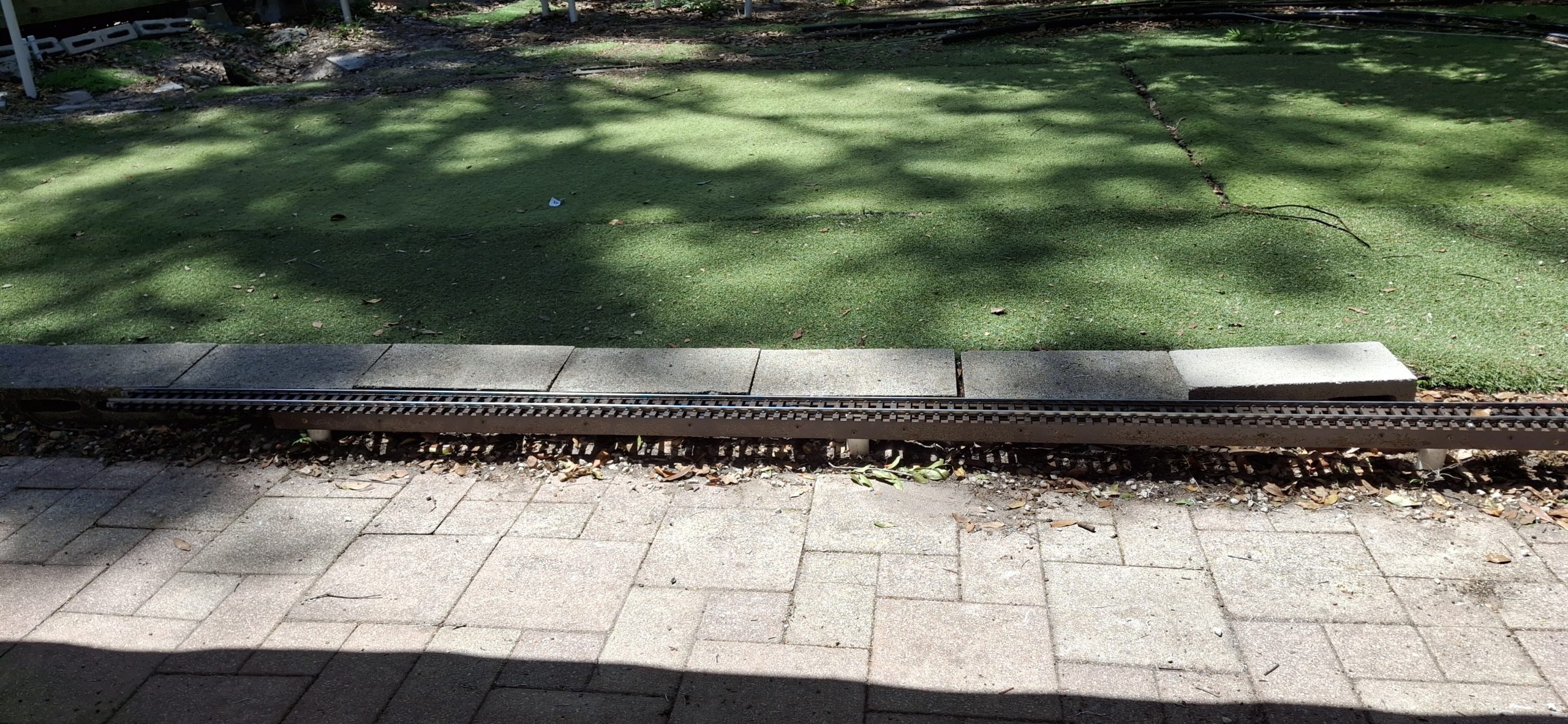
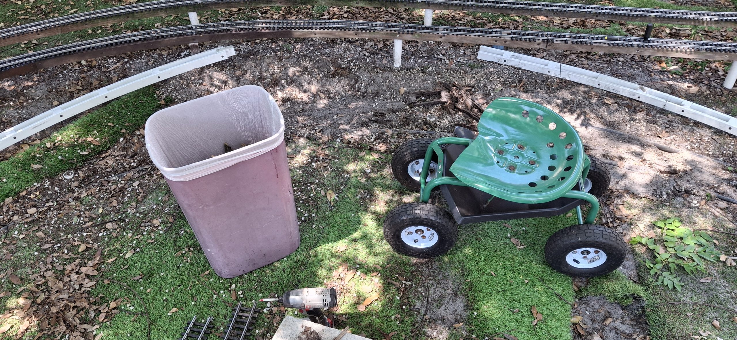
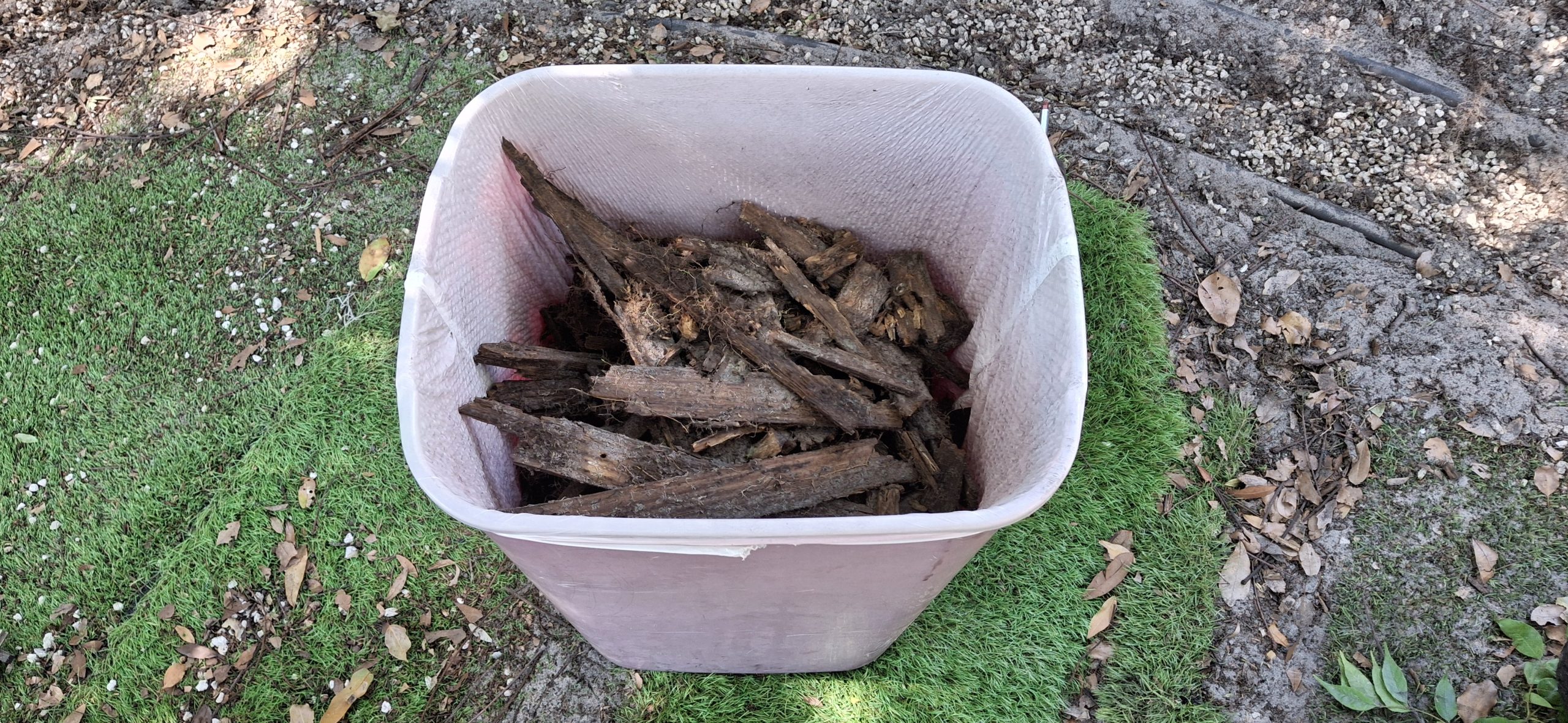
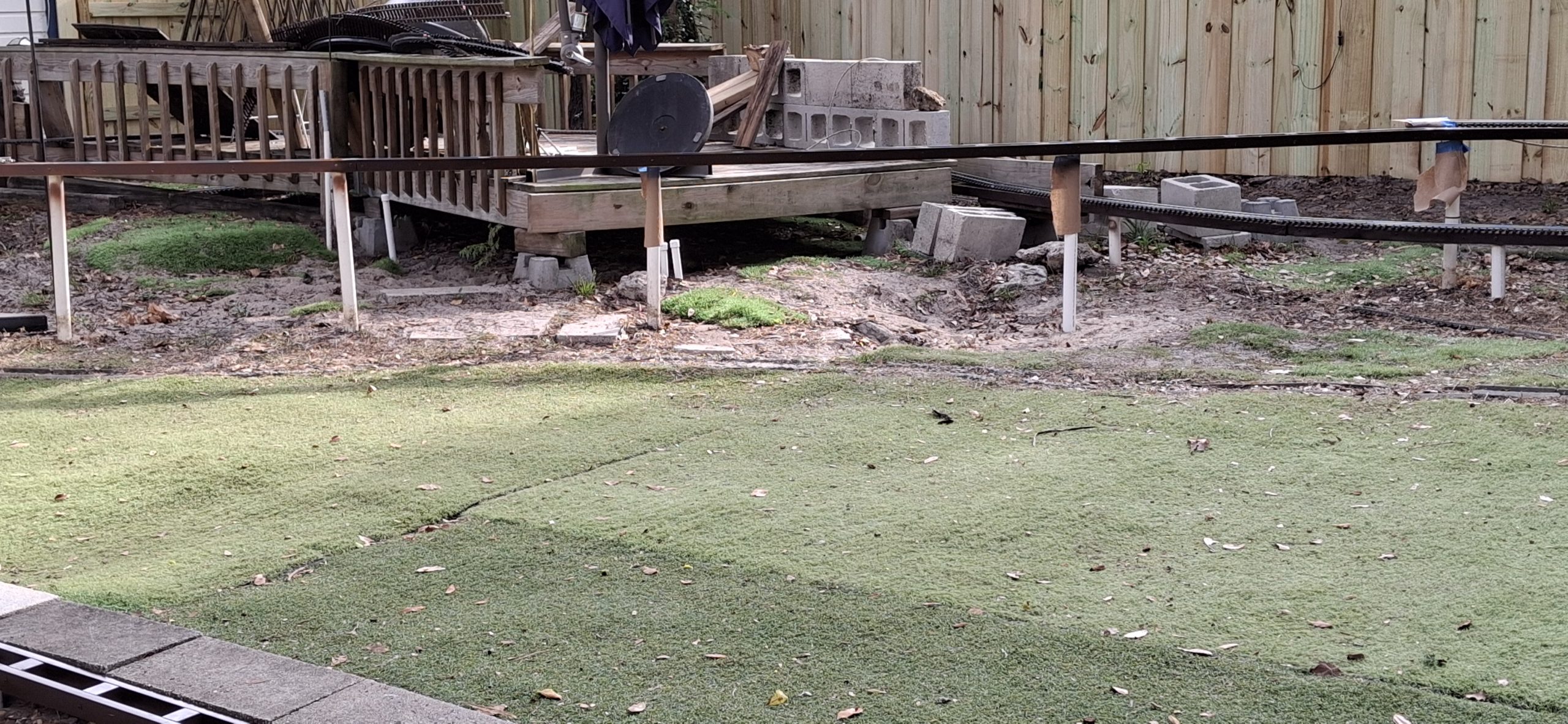
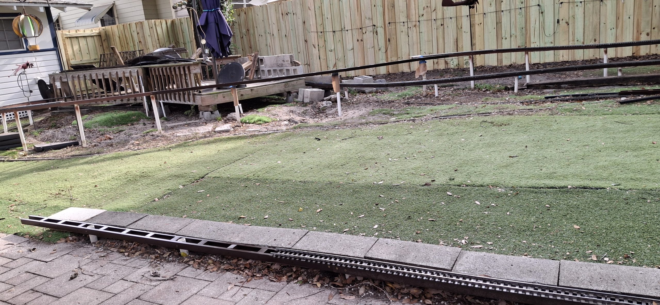
We almost got the wye finished, but had to stop and make sure we’re ready for the new fence to go in this coming week, the first full week of May (2026). So we also spent this last weekend pulling out the rest of the track and rotted stringers from behind the shed in preparation for the fence builders to come in and replace the fence. Wasn’t much left but the track itself and just a single 10′ diameter wood stringer still in fairly good shape.
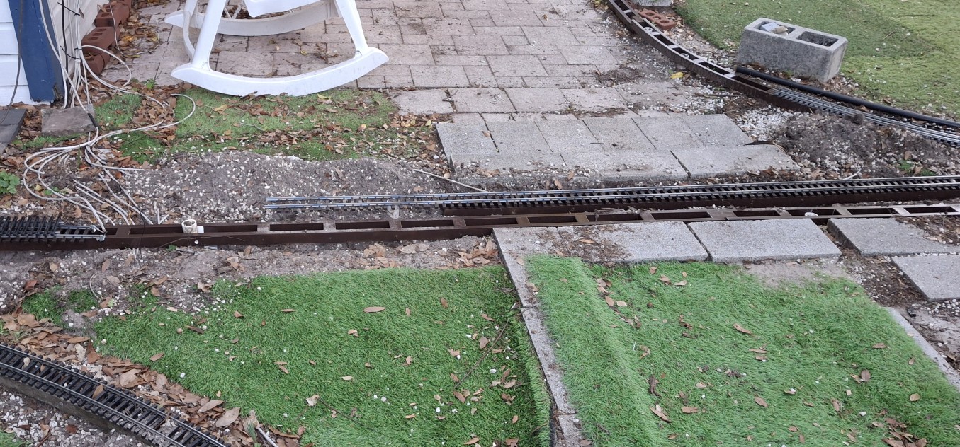
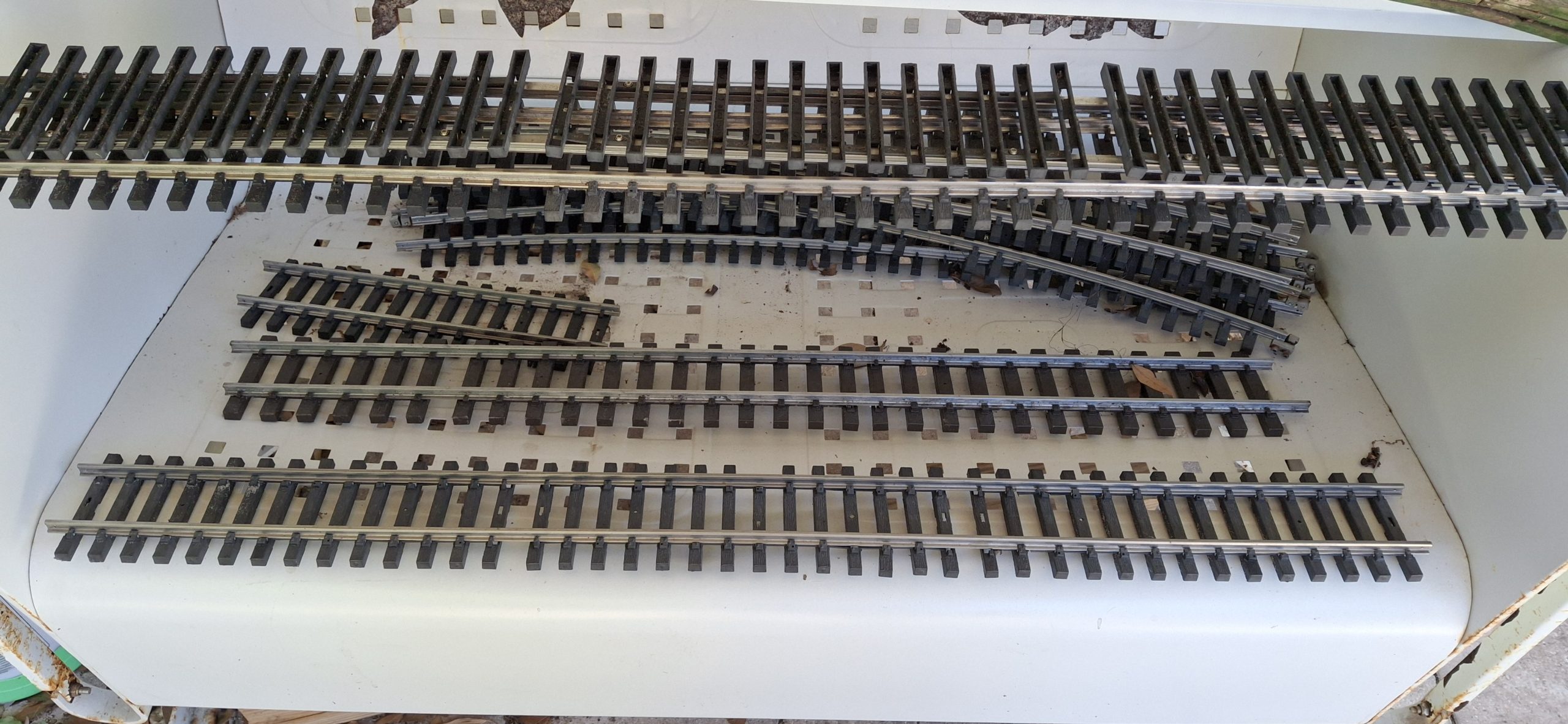
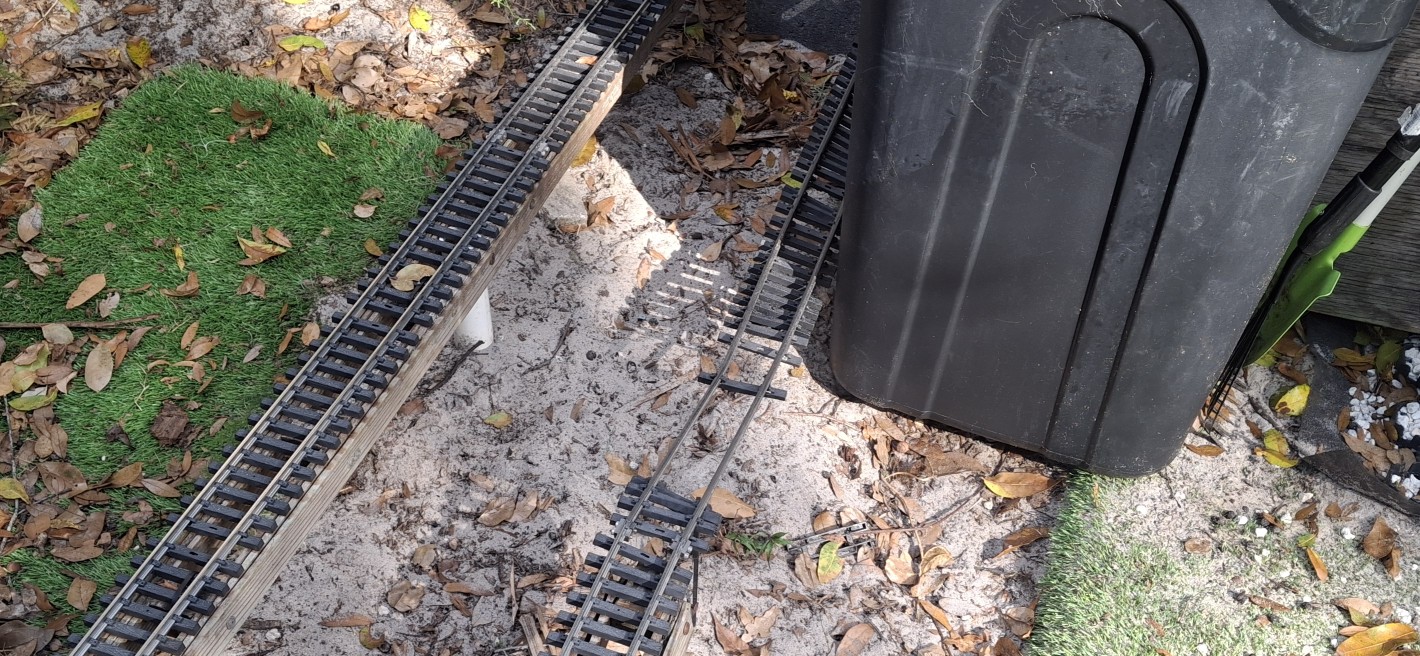
Even that totally destroyed 3′ section of track came out, the one that hurricane Milton blew down a big chunk of the tree on that caused all the damage. Speaking of that destroyed 3′ section, I managed to get both rails straightened out and the tie strips back in place and screwed securely to the rails. Like it never happened! I was amazed that just sighting down the rails and some time with the rail bender was all it took.
But that wasn’t the only piece of track repaired. Add two 5′ sections to the list from yesterday. Just about every piece of track needs disassembled and the tie strips “reseated” over the foot of the rails before the track can be put back in place. Anyone who’s ever dealt with those annoying little Aristo-craft screws knows what a pain they are. My big hammy hands make it even more difficult, inevitably losing some of those fumbly screws in the process.
As an example, one of those 5′ sections was missing every fourth screw. I have some replacements but they only thread in a little over a turn before binding, like they’re the wrong thread pitch, so I gave up on that. Some are better than none. When you get right down to it, are they really necessary at all? Those Piko tie strips for the flex track have none and still hold the rails just fine.
Fence Break’s Over!
Fixing the track is about all we’re able to do while they remove what’s left of the old fence and basically build our new board-on-board fence in place, from scratch. I say they, but it’s basically one very dedicated individual, John, and he knows his stuff! Over the course of four days he nearly single handedly built our new fence. He had a “new hire” one day, but he quit and left early on his first day! We’re simply amazed by the quality and craftsmanship. And it looks awesome!
Judge for yourself. All but one of the pictures so far show the old, dilapidated fence in the background. Those pictures that follow will have the new fence in the background. Ann’s already out there stringing up the lights, and doing it the way she wants them done this time around, stretched straight and level. No sagging allowed! We even rerouted the dedicated extension cord around the back of the garage instead of draped over the track in front of the shed. Much better!
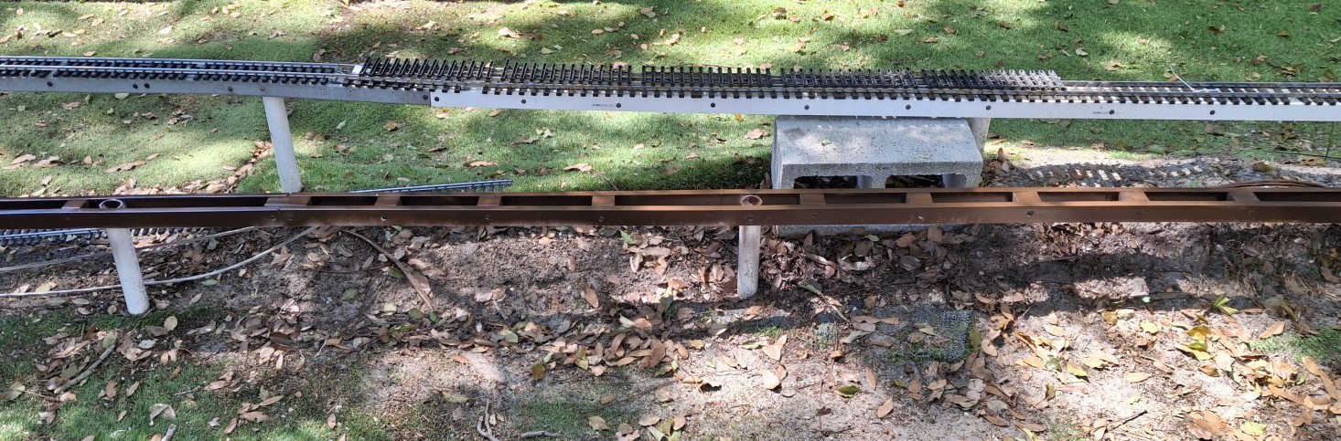
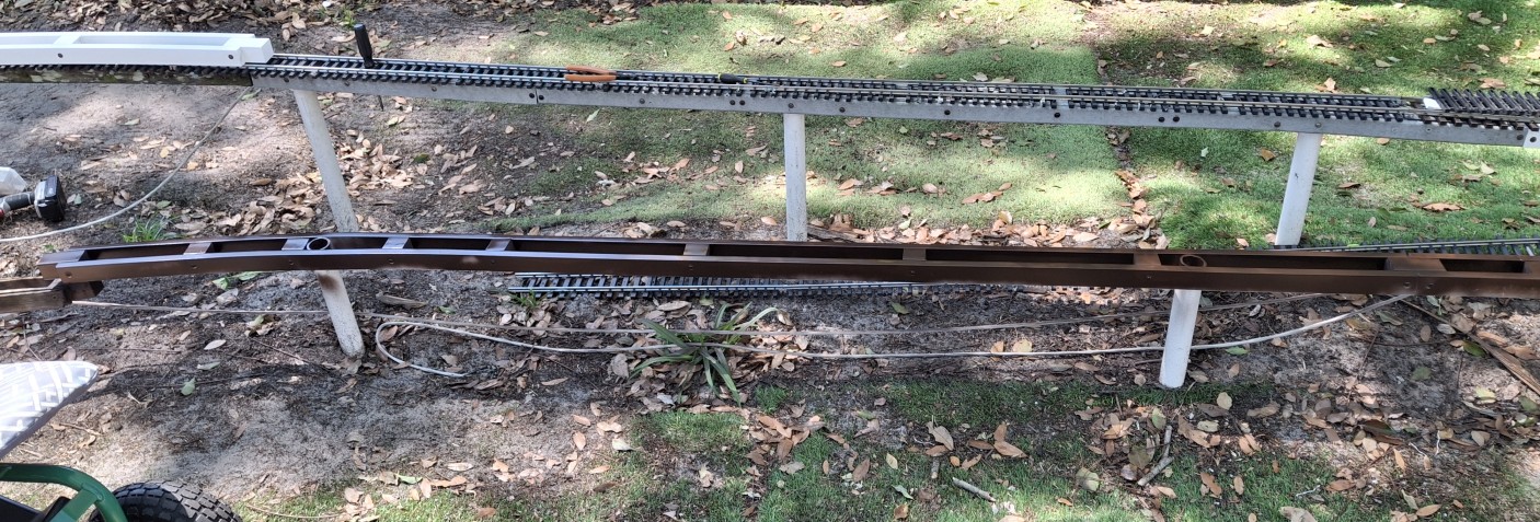
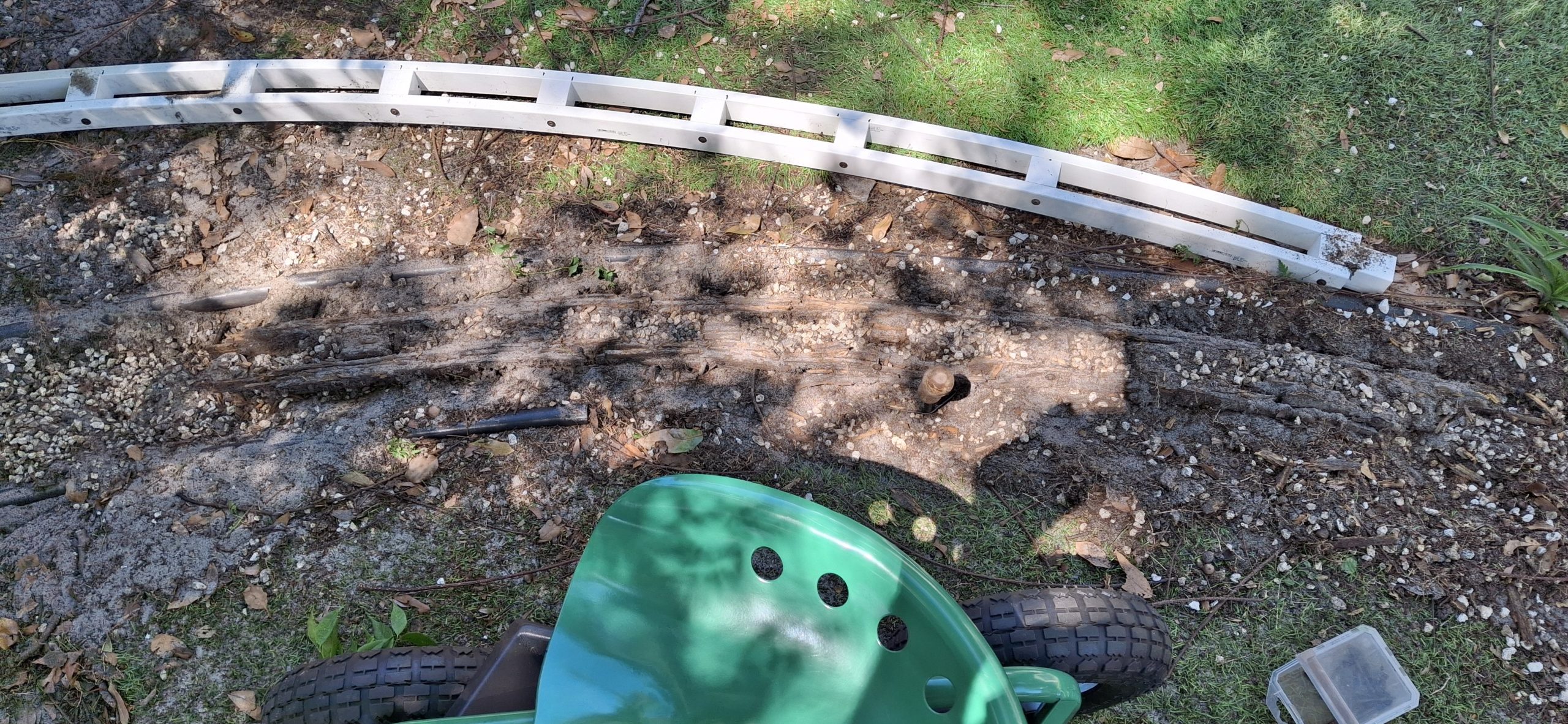
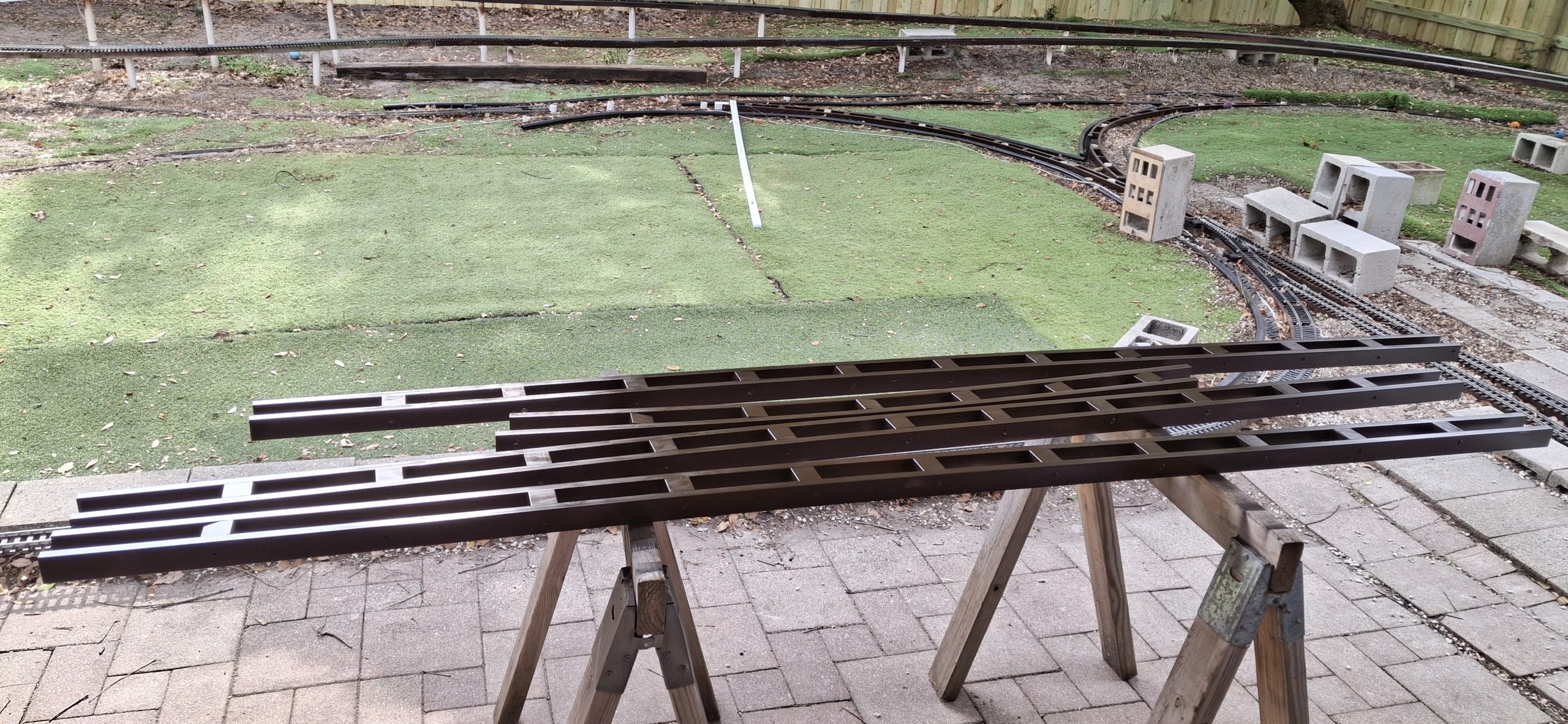
Time to get back to replacing the stringers. All the curved stringers we need are already finished, painted, and installed. Time for a bunch more straight ones. Two for the bridge section by the deck, two for the straight leg of the wye, and another to complete the station siding. Another weekend, another set of stringers installed. All but the straight leg of the wye. That’s going to take a LOT more work to finish.
Not only does the dirt need dug out, but there was turf under the old stringers, meaning it will need cut out of the way first, just to be able to get to the dirt under it! We’ll save that for next time. For now the progress is impressive. And more than we originally planned. But to make the wye a reality, we’ll need that curved switch. Good news everyone! That’s already in the works. I spent the week the fence was installed working on the design, captured in this post.
For A Limited Time Only
I’d been gathering the footage of the progress from the surveillance cameras, thinking they could be spliced together into a sort of time lapse montage. But then I missed the window to grab the footage from a couple weekends now. I’m surprised by this since I’ve been able to go back more than a week in the past. I can’t remember the last time I wasn’t able to. Oh well, I’m down to my last 3GB on a 4TB drive, not sure where I would have put it anyway!
Add the footage of the fence installation to that and we broke the bank, so to speak. I hastily rearranged data on the network storage server and removed duplicated items to make space for this video and more. I’m not real comfortable with the single point of failure state that left a lot of the existing captured video in, but I haven’t done anything with it years later, so chances are I’ll never do anything with it anyway and it’s just wasted storage. Time will tell.
For now, we’re busy with a single goal. Get. Trains. Running. Will we get there by Memorial Day? We’re definitely cutting it close with just one more weekend until Memorial Day weekend. I hate to leave you with a cliff hanger, but if you want to find out, you’ll have to stay tuned for Part III. I will admit we’ll be pushing it just to get all the stringers replaced, let alone all the track relayed.
Question? Concerns? Leave A Comment!
If you have any questions or concerns, please feel free to comment on this post. In any case, you’ll need to create a user account to do so. We don’t use any personal information for marketing or to spam you (see our privacy policy). We do it this way to avoid scammers spamming our posts. You’ll receive a verification email. Reply to the link provided to verify your email address. After that, it’s all automatic. No waiting on moderator approval! No spamming your inbox with useless advertisements and “Special Offers”. None of that nonsense.
More to come. Stay tuned for Part III!