The Battle Continues
It goes without saying there are even more stringers in need of replacement! It’s been difficult to keep up with only weekends to effect repairs. This says nothing about new additions or improvements so far. More stringers. Ugh. It should be obvious from that statement we have yet to get to any casting whatsoever. In fact, we’re actually moving in reverse, removing track the dogs have knocked loose from the stringers, just hanging off the sides.
We had to put up “blockades” on either side of the shed to keep Kai from bounding on, and potentially breaking through, the fence. Unfortunately, she’s pounded those 10′ diameter curved stringers to pieces, literally. It’s the only place I’ve yet to remove the track where it’s hanging. In fact, there are at least two more stringers that need replaced to make that deadline and another section in need of repair as well.
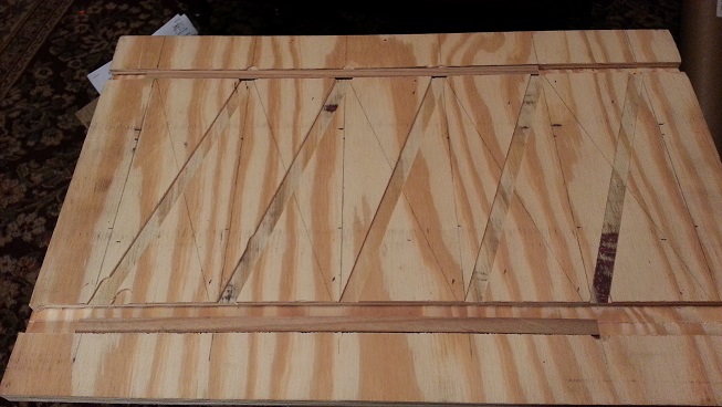
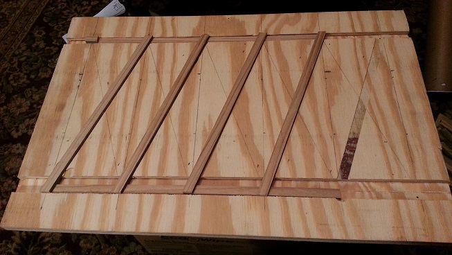
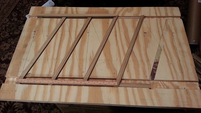
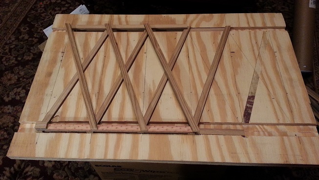
I’ve had a set of “plastic” 2x4s standing in the garage for years now, with the intention of using this material to construct stringers to (hopefully) last longer than any made from wood. I call them plastic, but they’re actually a composite of wood and plastic. I ripped the three I had into slats last weekend and got the 10′ diameter curved stringer template out of mothballs in the shed.


I have to say I certainly hope they last longer than wood because they are especially more difficult to rip into slats than their wood counterparts! They don’t really make much “sawdust”. Rather, they create many small shavings that want to clump together, clogging the vacuum in the process. Not sure what make them want to cling to each other, but what a mess! Don’t think we’ll be using this stuff again. The PVC siding I used to replace the bottom course of shiplap didn’t make this kind of mess, so I was surprised.
Our New Deck
Like last year at this time, we’re shooting for running trains Memorial Day weekend. There’s still quite a bit to do, and the stringers aren’t the only repairs that are need. The constant pounding by the pups has once again destroyed the two curved legs of the wye. One rail will need bent back to the proper radius and made flat with the rest of the track. While I’m reluctant to just put them back in place, for now it’s the only way we’ll be running trains by the weekend, even with Friday and Monday off work.
It’s a bit disheartening seeing a stack of track sitting on a rocking chair on the patio and all those stringers we replaced with no track attached. It’s been months since we’ve been able to run trains. But all this doom and gloom is balanced by our deck project. The deck is coming along nicely and nearing completion. The deck is actually part of the road bed for the new upper loop! It’s a cozy place to be, surrounded by trains as they pass. At least that much is nearly complete.

We still need to work out how to craft the short tunnel section where the lower loop passes under the middle section and meets the deck. For now it’s just makeshift stacks of concrete blocks and decking “cut offs”. We decided not to extend the deck all the way to the planters along the fence to leave ample room for the dogs to run and chase each other. Kai can really fly when she’s chasing those pesky squirrels!
Along those lines, we’ll need to figure out some other means to blockade Kai from behind the shed and accommodate running trains. We’re thinking some sort of tunnel entrance on one end and perhaps a giant industrial building facade with through passage beneath. I don’t recall what prototypical building this represents, but I do remember seeing one like this somewhere. At this point, anything will looks better than the chunk of plywood and section of fence we’re currently using, neither of which will allow trains to pass.
Other Improvements
As part of the deck improvement, we’ve added an underground power feed and a number of irrigation lines out to the deck. It’s a start anyway. The idea is to get the trenching done and out of the way before we continue to add more dirt to the planters that back up against the deck, to avoid having to move it more than once. It took several weekends to accomplish, starting with the first ten feet from the house to the edge of the lower loop.
Actually, it passes just beyond the lower loop, but that first ten feet is where the dogs like to chase each other around. We want to make sure it’s backfilled so when the pups play they won’t get hurt. The first four feet is basically just pavers out from the house, so the most difficult part was moving the dirt elsewhere rather than piling it on top of the pavers. From there, the next five feet is covered by artificial turf that we pulled back out of the way, and now a tripping hazard.

Even using the “banana” shovel, a long and narrow shovel meant for trenching, it takes into the afternoon to get down to 18″ deep for the conduit. Once the conduit and elbows are glued up and placed into the trench, it’s backfilled and compacted to about 6″ deep for the irrigation lines. Three of them, to be exact, basically ¾” PVC to support multiple irrigation zones. Those are backfilled as well to where the turf can be laid back down to cover the path.
Not sure what happened with the stretch of conduit at the house up to the outdoor in use box. It measured 44″, then fell short by 4″! You’ve heard “Measure twice, cut once”? Try “Measure thrice, cut twice”… It’s not that big an issue, just means it will need a splice before landing it in the box is all. For the irrigation lines, they stop short of going under the deck, mainly because some of the decking will need removed to gain access beneath in order to finish trenching.
Future Enhancements
Obviously we need to finish up the “utilities” to and around the deck. The conduit and irrigation lines now extend to roughly 20′ from the house, but remain unterminated. Unfinished. Most of those improvements will be covered in the deck series and not here. Eventually the conduit will feed power for lighting and other features on the deck. The irrigation will split out in “T” fashion, one leg heading to the planters along the fence, another toward the other planters along the other fence by the garage, and the third will feed the deck area and terraced planters themselves.
The pond was definitely an enjoyable feature, even with its drawbacks. The problem was no planning or thought was given to an overall sustainable system, not even basic filtration, and that became its undoing. Having to constantly drain, clean, and fill the pond on top of constantly toweling off the dogs was just too much like work.
At some point the idea is to add a waterfall at the end of the deck, and perhaps more of a “water feature” to go along with it. Another idea is to place a water wheel powered grist mill near the waterfall, fed by the higher head upstream, complete with rail siding to serve it. These features would take the place of a railing, providing a “natural” transition back to the railroad near the bridges. We’ll need to get closer to completion on the deck before that.

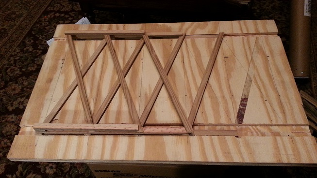
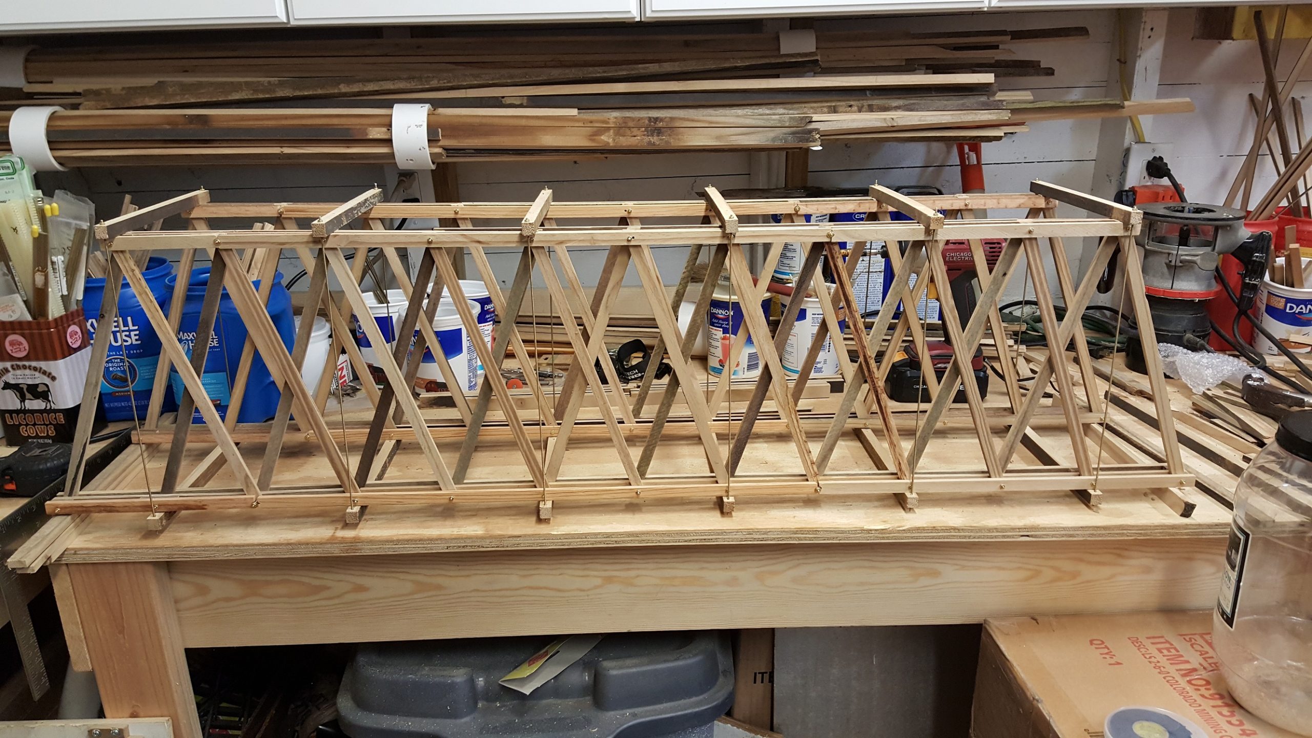
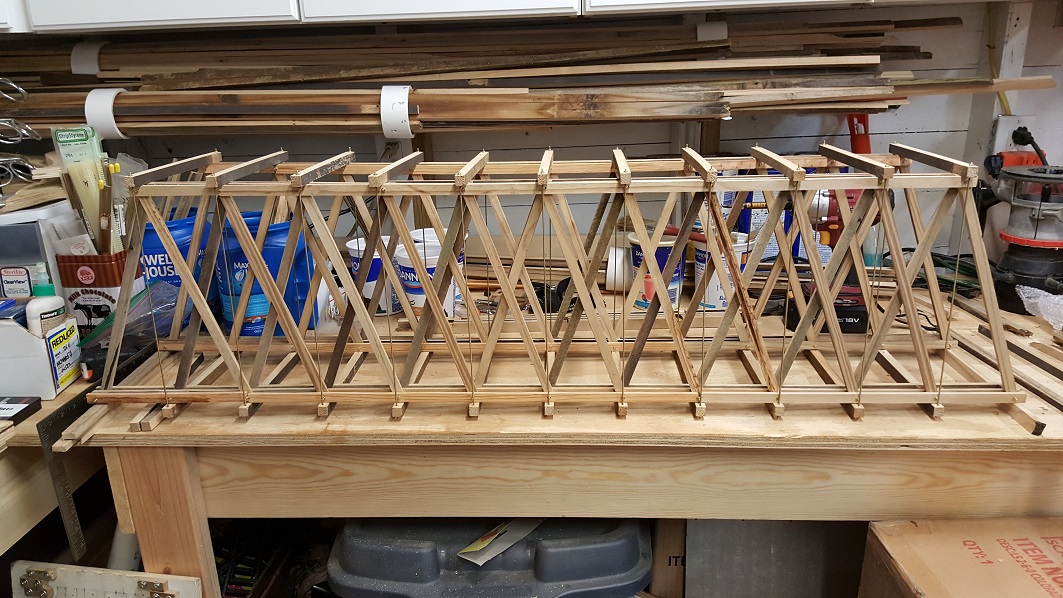
Speaking of bridges, plural, we’ll need to rework the existing scratch built Howe truss bridge into two. It may be easier to just scratch build two new bridges and save the old one for later. Still back and forth with whether to make the new bridges more modern steel versions or stick with the old timber style. We’ll need at least one more bridge for the section of triple decker that passes over the ground level lower loop track.
Before all that, castings. We’ve said it before, and we’ll say it again, castings are on the way. Once the 3D printer is tuned up and back online, we can print the molds we’ll need to cast the cut stone arches, and hopefully “restore” the downtown marketplace. And by restore, we mean rebuild. There’s more design work to be done around downtown before we can get to that, like how to route “utilities” under the streets, and how to pour the concrete for the streets and building foundations.
For now we’ve just removed what was left of the crumbling backer board that once provided a convincing illusion of main street and covered it with artificial turf. Jasper, a 12 week old puppy and the latest addition to our team, has a way of finding anything and everything we don’t want him getting into. It’s a full time job!
Once we collected up the pieces of backer board to keep him from chewing on them, he found the little stones in the gravel beneath that provided the road base and proceeded to chew on them! After covering the gravel with the turf, you guessed it, he started chewing on the turf and dragging it up by the corners!