Welcoming Spring With New Stringers!

Welcome back! We’re welcoming Spring with new springers, er… stringers. To celebrate the first day of Spring, we got out in the Barkyard to begin the annual stringer replacements. Well, technically it’s the second day of Spring, but close enough. We never expected this to become an annual event, but that’s what it is now.

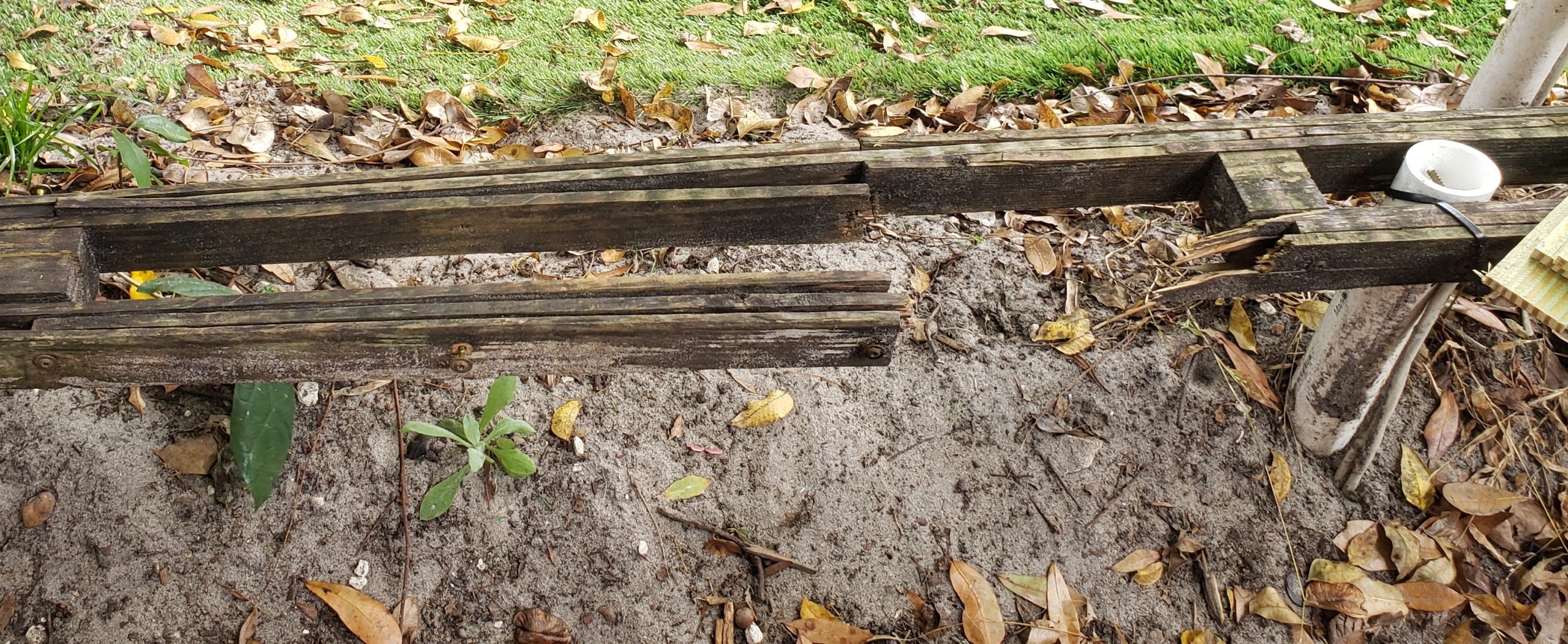
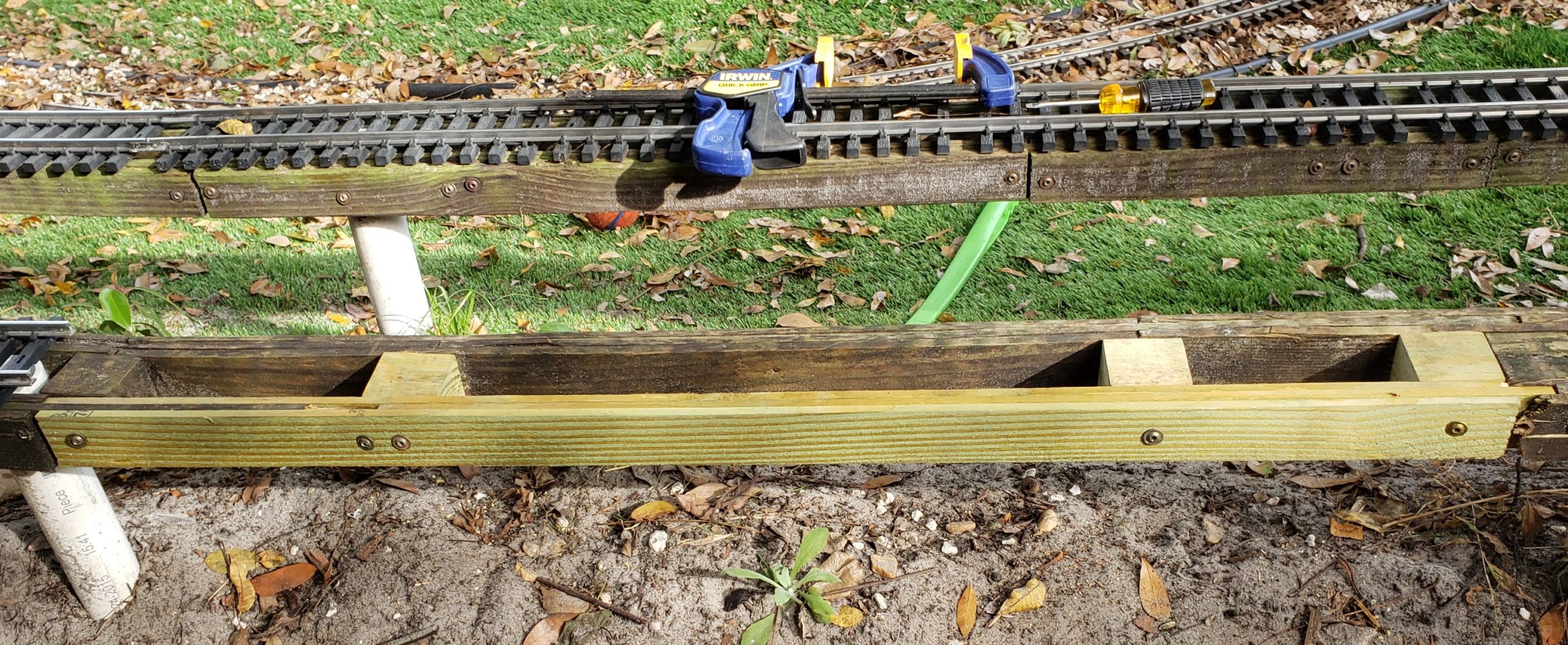
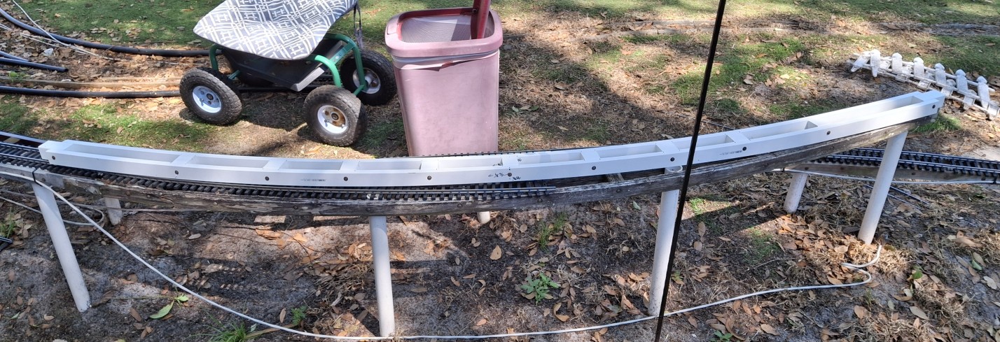
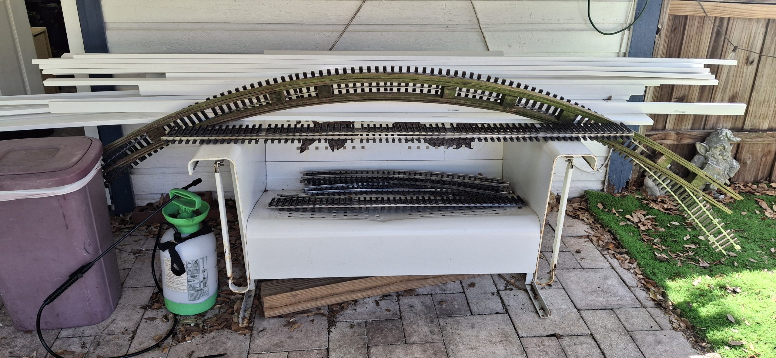
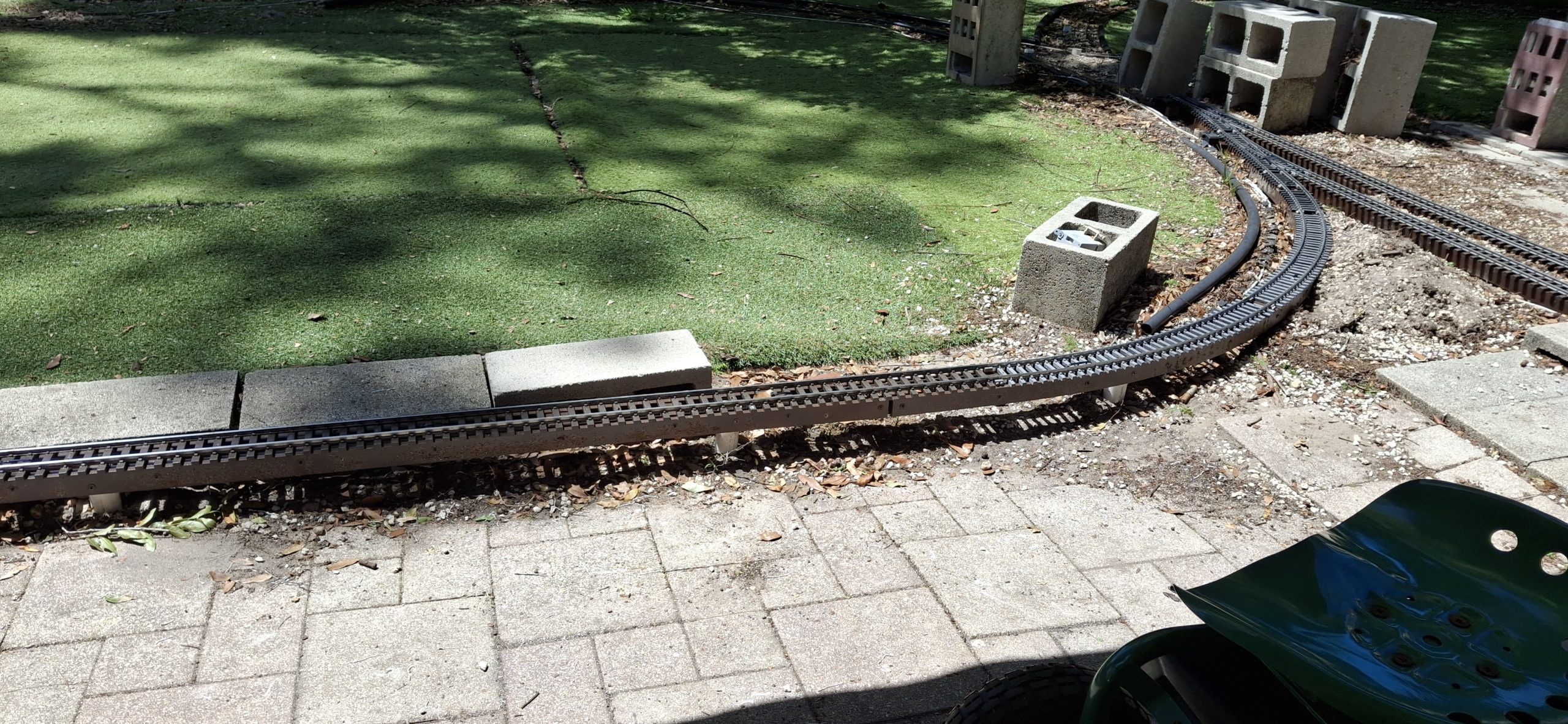
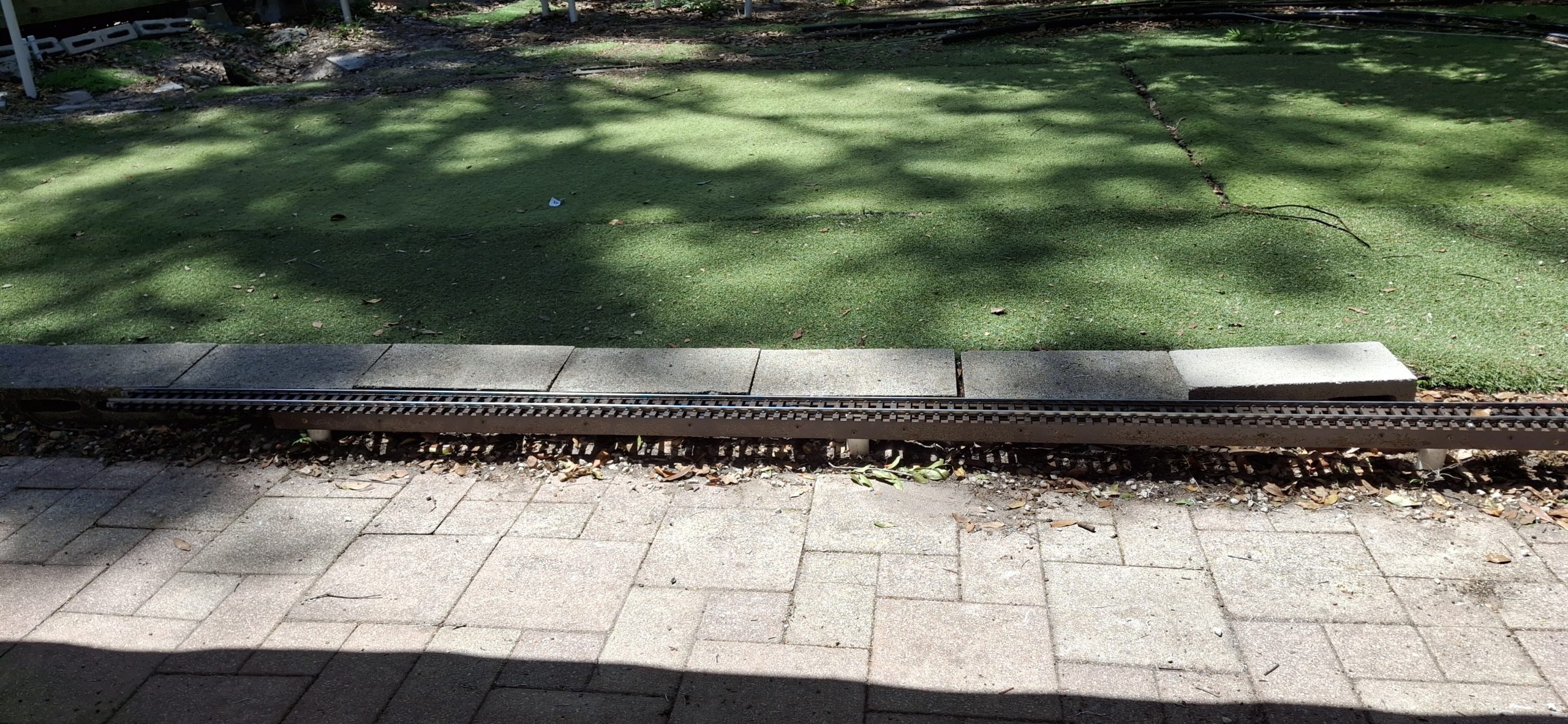
Learning the hard way that modern wood products just don’t stand the test of time out in the elements. Not even when heavily treated to do so. Those wood stringers offer a sturdy base for our track and elevate much of our rail above ground. Inevitably those wooden stringers rot. Last fall, we decided to try using PVC to replace a few rotted sections.

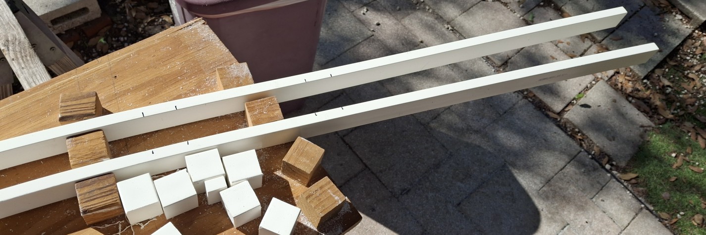
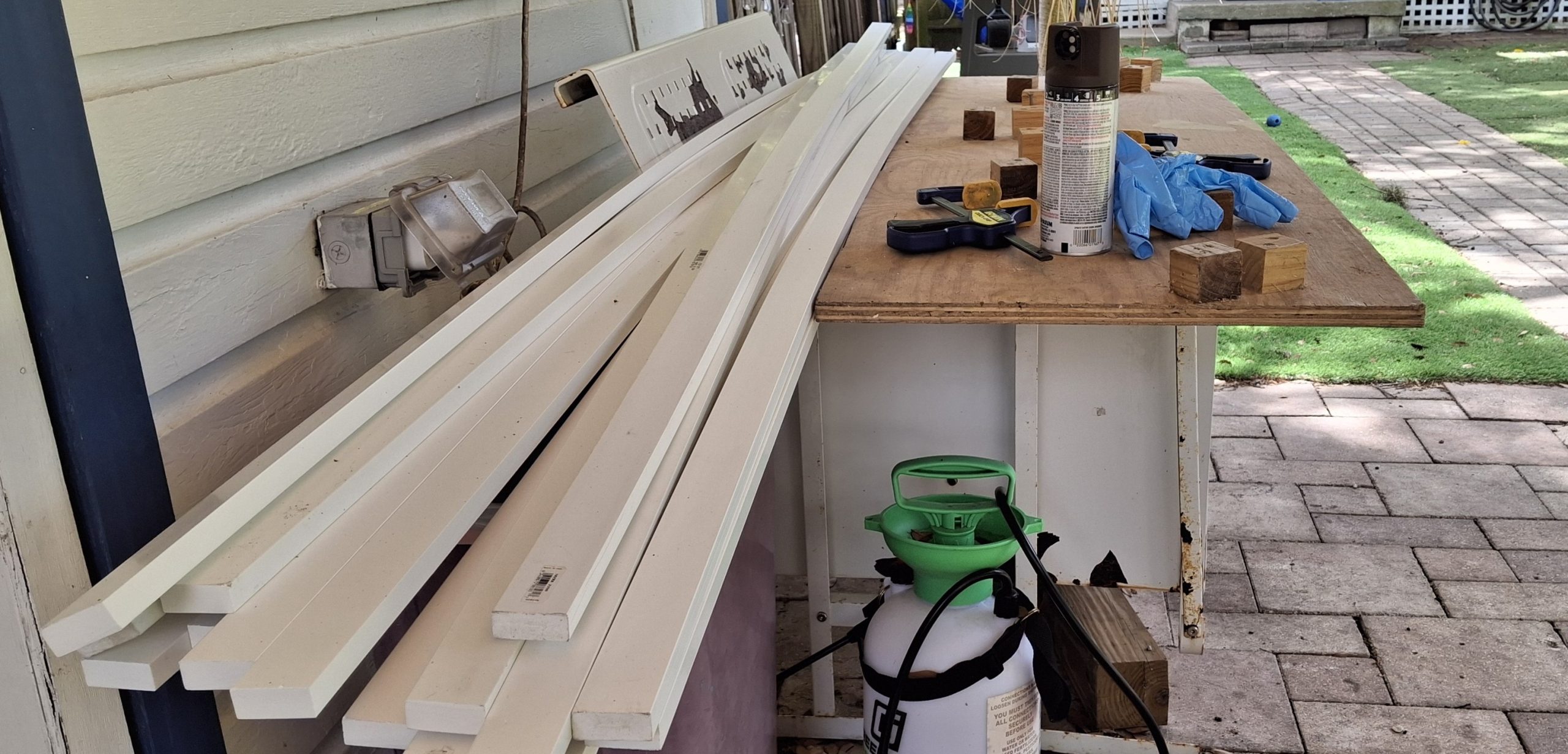
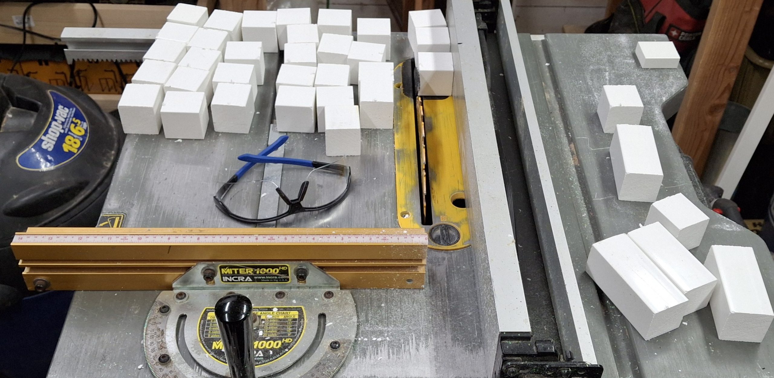
There are advantages to using PVC trim over pressure treated (PT) lumber. First is reduction of effort and waste. To construct wooden stringers, we rip a 2x4x8′ stud into not quite a dozen ¼”x1½”x8′ slats. It’s labor intensive considering the time spent at the table saw and it’s wasteful as each rip turns ⅛”x1½”x8′ into sawdust. That’s one third of the raw material converted directly to waste!

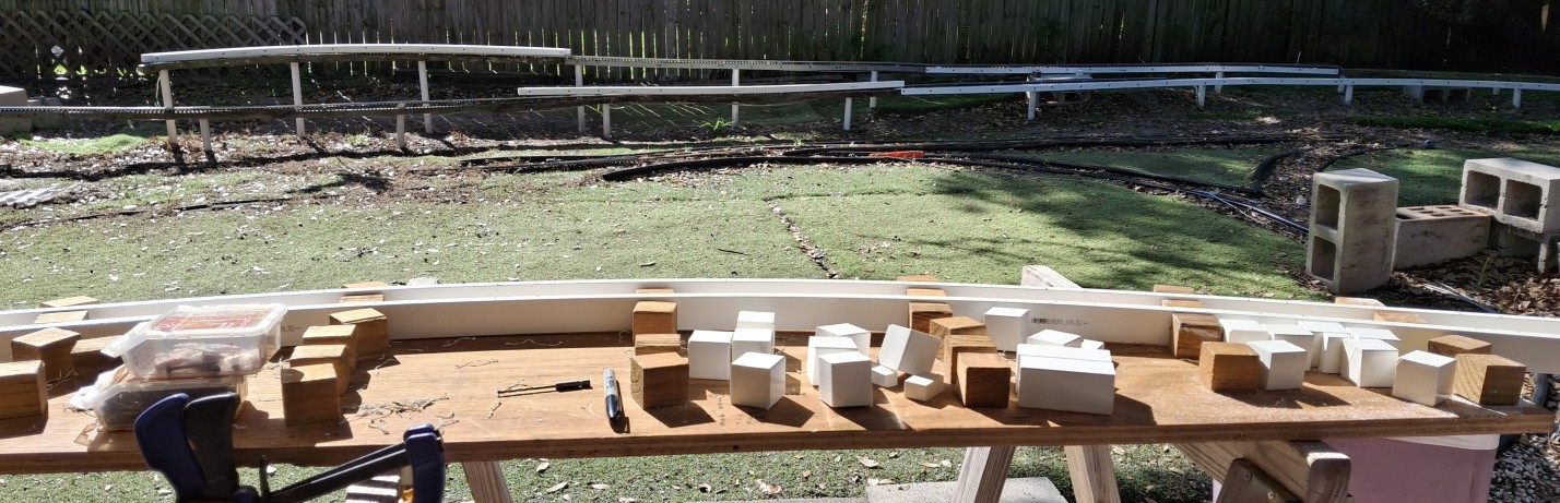
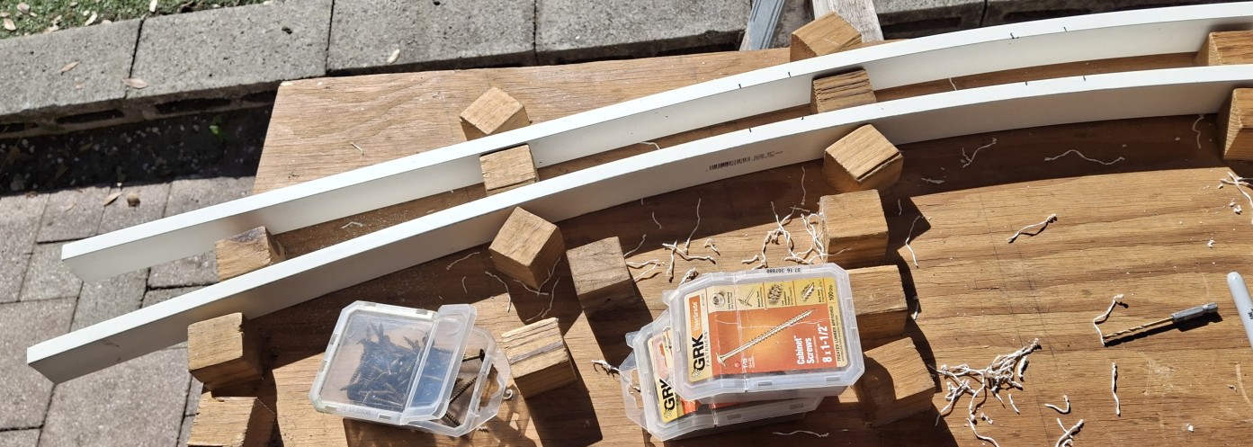
Another advantage of PVC stringers is ease of assembly. Each side of the stringer is now a single ⅝”x1½”x8′ PVC trim piece, not three slats that all need trimmed to different lengths when using the curve templates. I built those templates to help ease assembly, wrangling all six slats and a dozen spacer blocks into some semblance of order.

Let’s Do This The Easy Way

Now it’s just a single pass with a pair of the PVC 1x2s, drill and screw each to the spacer blocks, then trim either end and done. It still takes about an hour to assemble an 8′ section of stringer, but it saves about another hour of ripping a 2×4 into slats, not to mention the countless hours of removing rotted sections and replacing them every year.

Speaking of those jigs, they’re not really necessary when using PVC. Assuming the posts are arranged in the desired pattern, circular or otherwise, just attach the spacer blocks to one side then fasten that in place along those posts. Attaching the remaining side is easy enough using clamps to hold it in place while fastening it to the first side and posts.

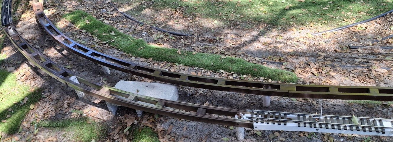
So far we’ve used the 14′ and 20′ curve jig. The 10′ diameter curves could be a different story. We skidded the shed out from the fence another 8″ a while back with the hope of fitting larger curves to replace those tight 10′ diameter sections. They were enough to get us up and running originally, but now we have flex track and a rail bender to fit any size curve.

Getting A Head Start

Every year there’s a push to get trains running again. This year we’re starting earlier than most, in the past usually waiting until May to get trains running by Memorial Day. Some years that even stretched to July 4th. And every year it’s the same thing. Replace the rotted wooden stringers. As we said, it’s become an annual event.

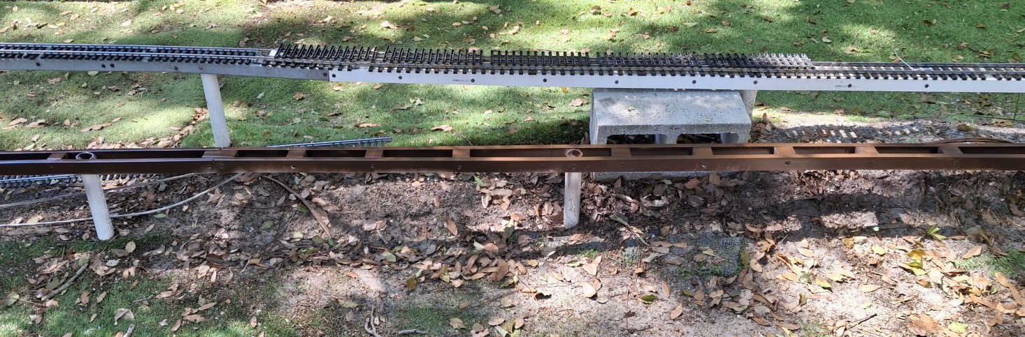
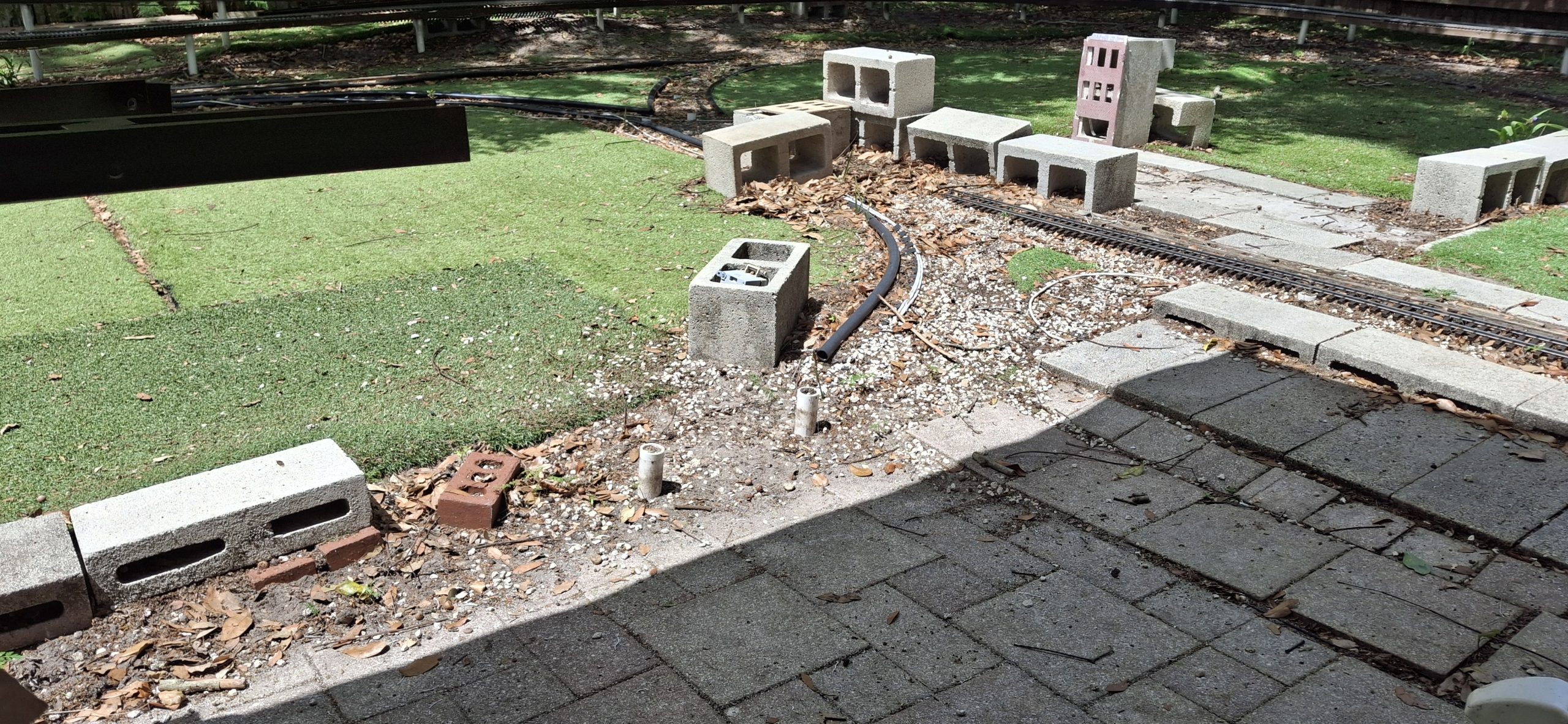
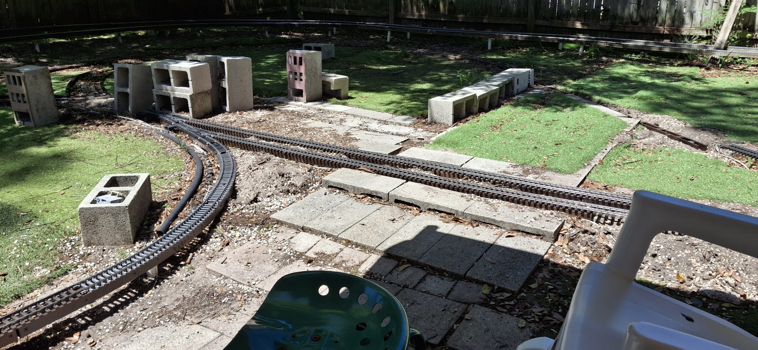
Those concrete roadbed “bricks” we’re experimenting with work, but are much more labor intensive than posts and stringers, and nowhere near as sturdy and immoveable as we thought they’d be. Still working on how to streamline that process… Comparing the ease of replacing the rotted wooden stringers with PVC ones with the amount of effort using concrete bricks, it’s a no brainer!

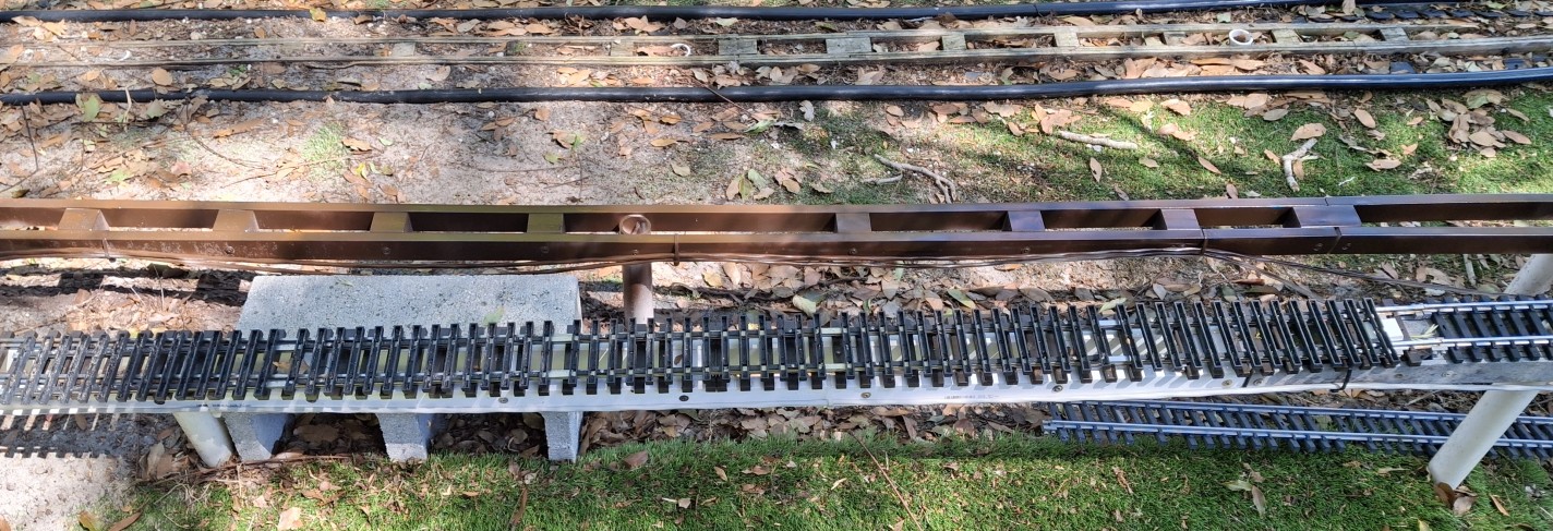
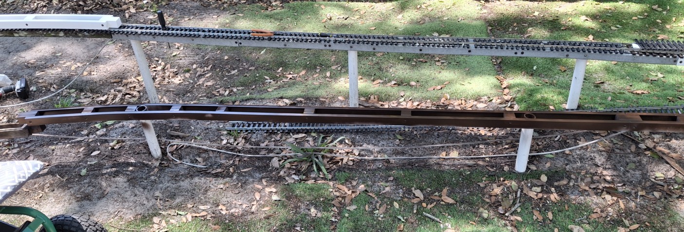
So far we’ve replaced about 100′ of stringers, both straight and curved sections, but we’ve also taken up more than 300′ of track where the stringers had already rotted out over the past year or so and no longer held the track. We’re still behind the curve for getting trains running by Memorial Day, but we’re working hard to make that happen.

Just Enough

The plan is to replace just enough track to have a continuous loop trains can run on. This would consist of the downtown loop, that North leg of the wye loops around through downtown along the mainline back to the elevated sections. The elevated sections need bridges in place to run trains past the deck and back to downtown.

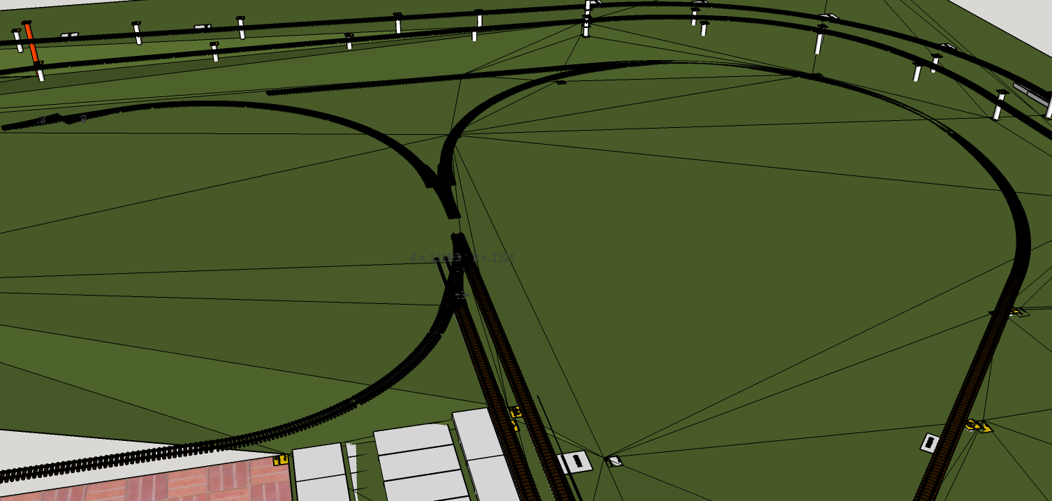
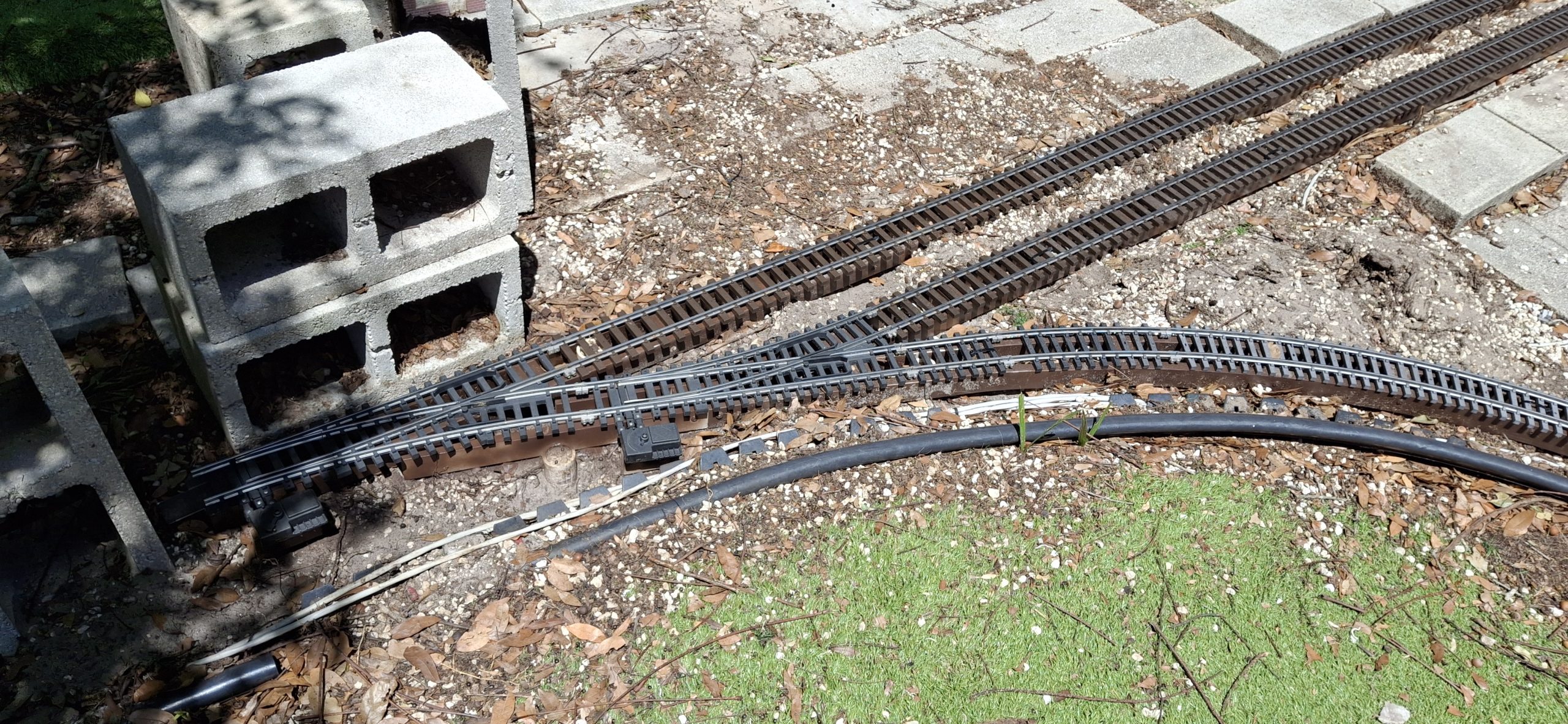
The lower loop around the deck and the other legs of the wye will have to wait. Essentially the mainline Downtown connects to the wye switch (West). The diverging legs of the wye arrangement go left (South) to the deck and right (North) to the downtown loop. The only thing missing to make it an operational wye is a switch connecting the North leg to the straight leg to the West.

But a standard switch doesn’t fit. When I first laid out that downtown wye section, I thought the Aristo-craft wye switch replaced a full 20′ curved segment of track. I found out the hard way it didn’t. Trying to fit those 14′ diameter curves to the diverging routes of the wye switch didn’t work as planned.

The angles were off just enough that it didn’t fit without having to resort to flex track and bending a tighter radius to make it fit. Without the wye switch in place, the 14′ diameter segments fit just fine. It may be better to redo that section to make it fit right while we already have it apart and all torn up anyway. We shall see…

Making Progress

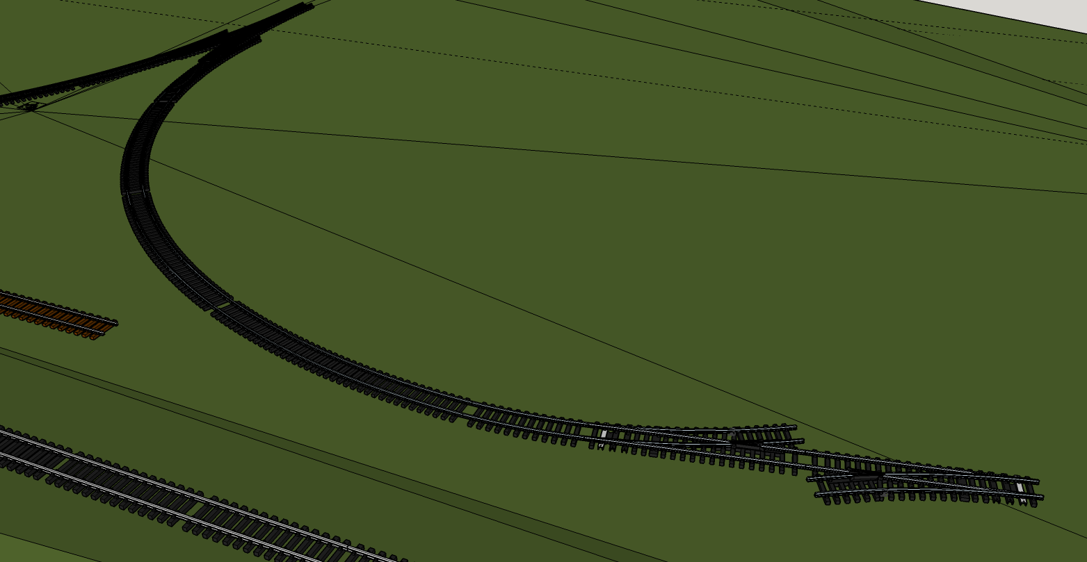
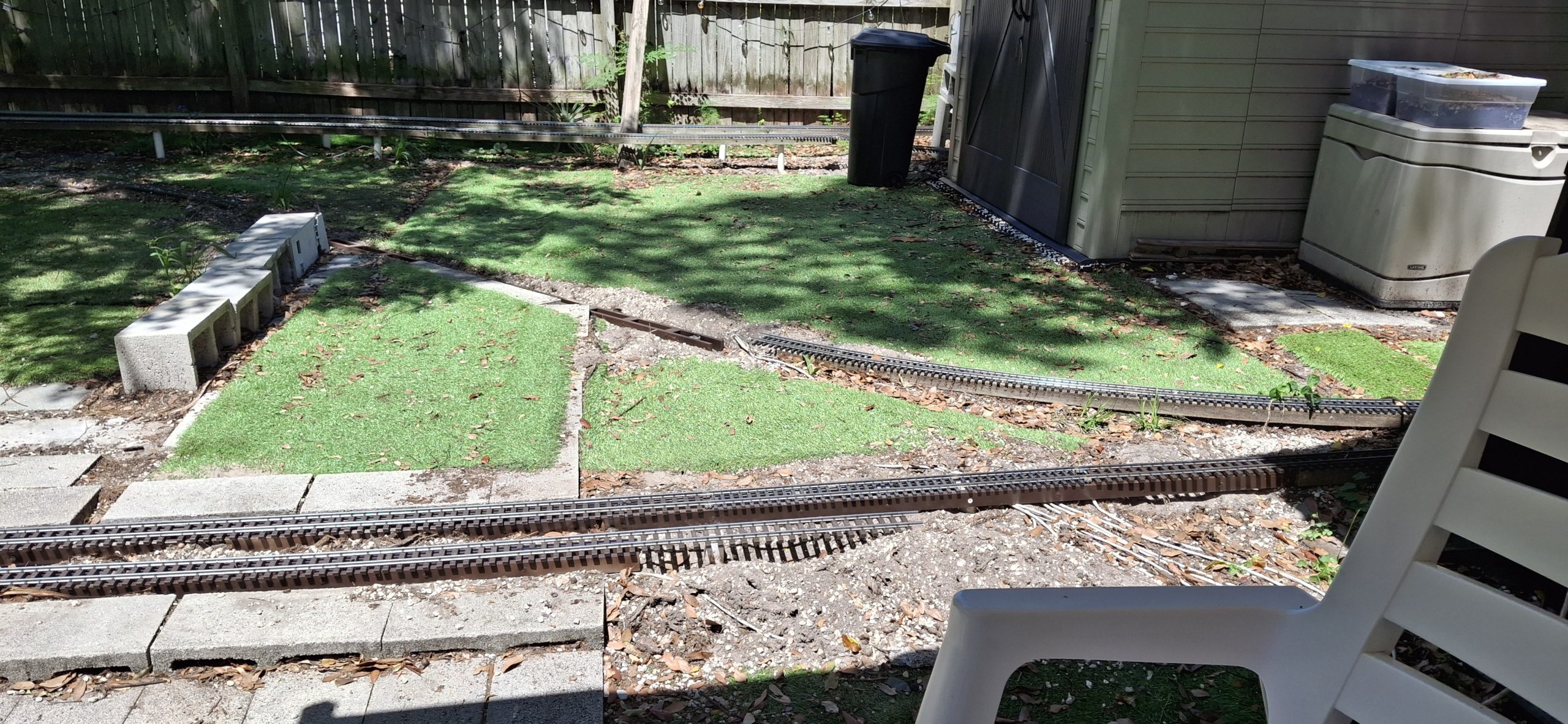
Amazing what was accomplished in a single weekend. All of the elevated sections are in place and painted with the track repaired and installed. That was easy compared to what’s next. The ground level sections, starting with the mainline and siding switches to the station siding. And there’s a reason for starting there.

Because of the “hiccup” with the wye switch not quite aligning with the diverging legs of the wye, that becomes the most important location on the layout. Everything has to be measured against and fit to that point. Why? Because the station siding just fits using 10′ diameter curves and the two wide radius switches. And that has to be the starting point for the wye switch.

Another consideration is the height of the mainline crossing Main Street into Downtown. The original track height is too tall by about the thickness of a concrete block cap, roughly 1⅝”. The quick and dirty way around that in the past was to just line Main Street with concrete block caps, simulating curbing, sidewalks and building foundations.

It’s A Dirty Job…

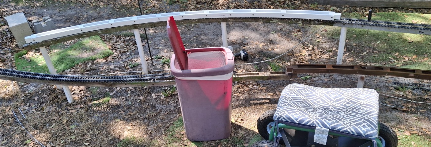
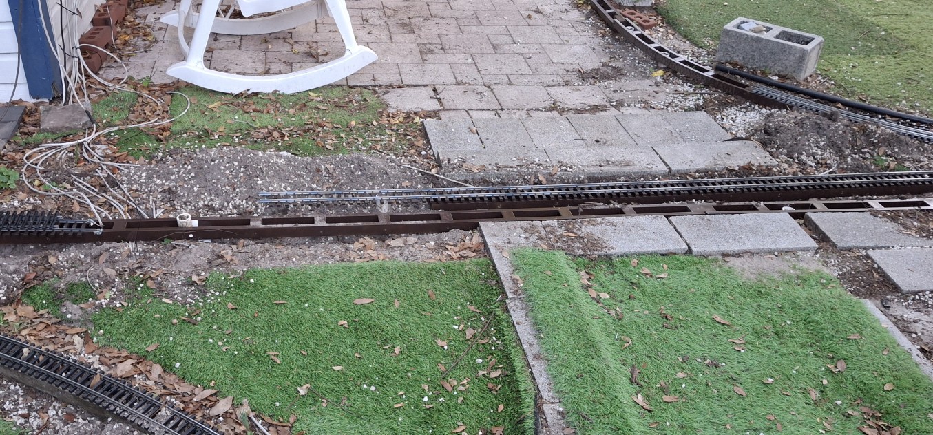
Time to start digging out what remains of the rotted mainline and siding stringers. I need someplace to put all the dirt and gravel while test fitting the yet to be assembled replacements, but somehow I’ve managed to use all the five gallons buckets for something else.

A number of unused 16qt storage bins with lids are sitting in the garage, so they’re pressed into service. Fitting the new replacements fills two of them! I hadn’t planned on fixing anything more than the station siding, but as the digging exposes more and more of what remains of the other siding, the danger of exposed screws is apparent. Better fix it all while we’re in here.

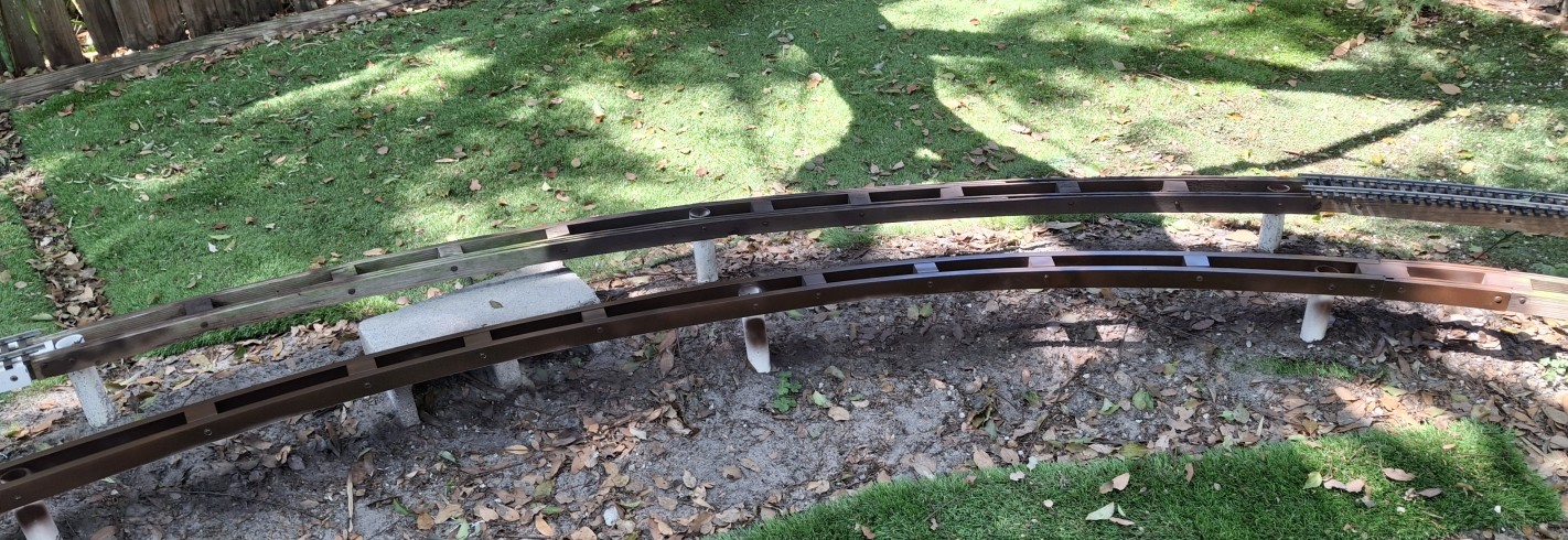
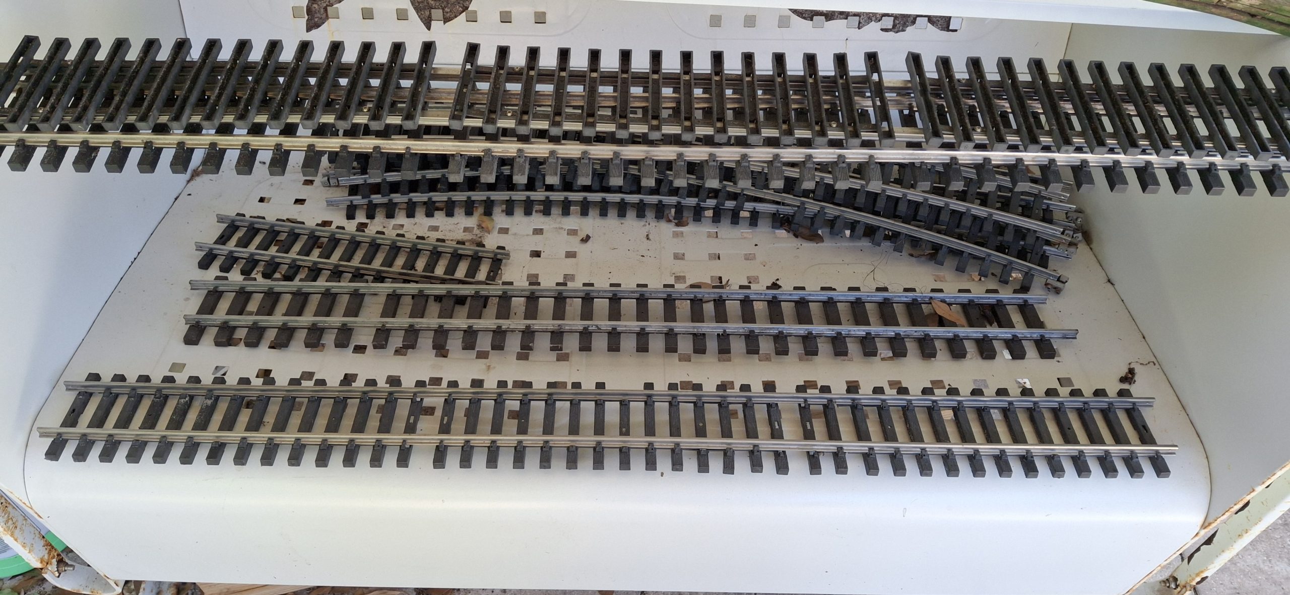
Those 10′ diameter stringers have always been right at the edge of being too tight of a curve for any material, wanting to spring back to their original straight shape when removed from the jig. Thankfully we only need two sections (~60°), not an entire quarter circle (90°). It’s still straining to maintain its shape against the posts, and the screws are pulling out of the twisting spacers.

Repairing The Track

About as common as replacing rotted stringers is having to repair the track. It seems that just looking at the track wrong will cause the rail to pull out of the simulated tie plates and spikes. Now consider three good sized German Shepherd “pups” constantly pounding on them. Add to that constant UV bombardment from our hot Florida sun baking them brittle and prone to breakage.

Just about every piece of track needs disassembled and the tie strips “reseated” over the foot of the rails before the track can be put back in place. Anyone who’s ever dealt with those annoying little Aristo-craft screws knows what a pain they are. My big hammy hands make it even more difficult, inevitably losing some of those fumbly screws in the process.

In the past I’ve tried to patiently coax the ties back around the foot of the rail using tiny screwdrivers and other tools with limited success. What usually ends up happening is the another tie gets pushed off the rail while struggling to hold it in place and fix the first tie. Anyone that knows me knows what little patience I have doesn’t last long with fiddly things like that.

Relaying The Track

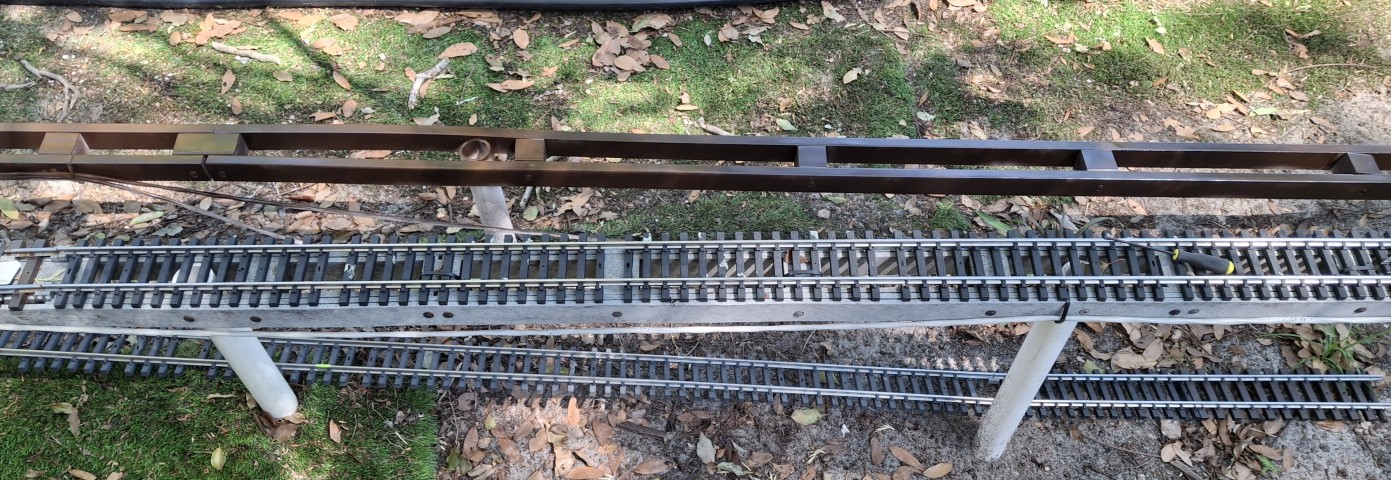
Anyway, each track section is laid back in its place as it’s repaired. SplitJaw™ rail clamps are then installed to connect it to the previous section. Learning from past mistakes, when securing a single tie with a screw to the stringer beneath, either the screw pulls through the tie or the tie gets ripped free from the rail, now uselessly still mounted to the stringer.

We recently switched to using zip ties every so often to hold several ties to an joiner block of the underlying stringer. It’s much more forgiving using this method. The track usually has enough give that it simply shifts to the side when absorbing impacts. That’s not to say that the track can’t still be damaged, but it certainly takes a lot more effort to do so.

Pulling the zip tie too tight is a quick way to cause damage.  The most difficult part is placing those zip ties when the stringers rest directly on the ground. It’s a struggle to feed them down through the ties, underneath the spacer block and then back up through the ties to secure them. But at least now the mainline and siding tracks are fully restored and in place.

What The Future Holds

Another weekend, another part of the Barkyard restored. The next big win would be to get the rest of the ground level track in place, including the rest of the wye. That’s most likely a future thing though. As it stands, the wye really isn’t a fully functional wye arrangement. The downtown loop doesn’t have the option of returning to downtown and looping back to the elevated sections.

It’s only connected to the straight leg of the wye using a 20′ diameter track section in place of the 14′ diameter section. That straight leg does have a switch at the other end, allowing trains to run along the lower loop around the deck and then along the South leg of the wye back to downtown and the mainline heading East.

What we need is a 14’/20′ diameter curved switch to connect the straight leg to the other leg of the wye. It’s not clear in those screen captures though. They don’t make 14’/20′ diameter curved switches. At least not that I’m aware of. There’s not enough room for anything else to fit. I’ve designed myself into a corner.

Spoilers

Back to the drawing board! Years ago I had started designing a home made #5 switch to connect a diverging 14′ diameter route with a 3′ long tangent route. I think I originally had the downtown wye in mind. I’ve put all the details in this post dedicated to the new switch design.

There’s a new discovery in there as well. One that could have MAJOR impact on Downtown! Let’s just say I can’t wait for my new 3D printer to get here! It’s due to arrive in the mid April timeframe. I ordered it back in November of last year (2025). Think of it as “next generation” printer technology compared to my other “first generation” technology printers, where everything is manual.

I’m looking forward to not have to manually swap spools of filament mid print while crossing my fingers that something doesn’t screw up. This new one can handle four different colors in one print. The printer actually supports up to 16 colors at once, but I opted for just the four in a single ACE cabinet to begin with. Not sure where I would put the other three ACE cabinets anyway.

For A Limited Time Only

I had been gathering the footage of the progress from the surveillance cameras, thinking they could be spliced together into a sort of time lapse montage. But then I missed the window to grab the footage from last weekend. I’m surprised by this since I’ve been able to go back more than a week in the past. I can’t remember the last time I wasn’t able to.

Oh well, I’m down to my last 3GB on a 4TB drive, not sure where I would have put it anyway! I was waiting for the 8TB NVME drive prices to come down, but with AI and all the global upending lately, that ain’t happening. It’s DOUBLE what it was last year! They want $200 more for the 4TB drive I already have! Also nearly double! And they want more AI and more data centers?

Don’t get me wrong. I’m not Grandpa Simpson shouting at the clouds. I’ve used AI in increasing capacities at work since before the Large Language Models (LLMs) emerged. AI has its uses, but it’s not the panacea it’s made out to be. It’s wrong more often than it’s right. And when it’s wrong, it still takes a human to detect those mistakes and retrain it to reduce their frequency.

At some point those rough cut videos will reappear, but not right now. We’re making too much progress toward getting trains running again.


Question? Concerns? Leave A Comment!

If you have any questions or concerns, please feel free to comment on this post. In any case, you’ll need to create a user account to do so. We don’t use any personal information for marketing or to spam you (see our privacy policy). We do it this way to avoid scammers spamming our posts. You’ll receive a verification email. Reply to the link provided to verify your email address. It’s all automatic. No waiting on moderator approval! No spamming your inbox with useless advertisements and “Special Offers”. None of that nonsense.

More to come. Stay tuned for Part II!

New Acquisitions 2026 – Part II

Welcome back. This is the second part of our New Acquisitions For 2026 series. We highly recommend starting there if you haven’t seen it yet. We’ll be picking up where we left off in that original post. And as much as I want to say we saved the best for last, it’s doubtful this will be the last post about our latest acquisitions.

We’re very excited to have added these classic Aristocraft treasures to our collection. These “relics” are quickly becoming unobtanium. For those that remain for sale, the sellers are asking outrageous prices, presumably because of their perceived rarity. I’ll add them to my watchlist just to see if anyone is crazy enough to pay those ridiculous prices.

An added bonus in having them on hand is it allows them to be copied. And by copied, I mean their designs captured and perhaps 3D printed. Not all of the original design can be exactly duplicated, like metal driver wheels and gearboxes and such, and even some of the plastics will require redesign to support the limitations of 3D printing.

But for the most part, those missing and broken parts can be replicated fairly quickly, and to a reasonable degree of realism. But we’ll get to that in a bit.

Run In Stand "Power Pod" For USATrains Equipment
Run In Stand “Power Pod” For USATrains Equipment

Where Did We Leave Off?

We’re getting set up to better test the mechanisms of these new acquisitions. That starts with a revised run in stand design that supplies power directly to the drivers. After the mishap with the test track, it’s time to get proper run in stands in place. But there’s a problem. The run in stands don’t have power feeds built into them.

Unlike their USATrains counterparts, Aristocraft doesn’t use power “skates” to enhance power pickup, but rather picks up directly through the wheels and axle bushings themselves. Our 3D printed run in stands rely on a separate “power pod” that feeds power up from the rails directly to those skates.

For the most part, a set of test leads can be clipped to the wheels of the pony truck on Aristocraft equipment. But on the custom Mikado, the power leads appear to have been deleted, presumably fallout from the DCC conversion. The main drivers still feed power from the track, so time for some mods to the run in stands themselves.

The initial thought is a quick and dirty feed through the bearings, thereby incurring the wrath of every jackal and troll on the internet, screaming “It will ruin the bearings!” in the comments. Well, stand down. That won’t work. Ask me how I know…

Attempt To Add Power Feed Thru Run In Stand Bearings With Copper Tape

That Would Be Too Easy

Unfortunately running the copper tape up from the rail to the inner bearing race doesn’t work. Apparently these bearings use plastic or ceramic balls because there’s no electrical continuity between the inner and outer races. Figures. That would be too easy…

So now what’s the plan? The only idea that comes to mind is some sort of “feeler” contact that rides directly on the outer race to feed power to it. That leads to thoughts of etched brass or stamped phosphor bronze contacts. Neither is quick considering the amount of time searching online to find something that already exists and will work.

Next idea. 3D print an insert to the existing run in stands with some sort of “springy feeler arms”. The initial sketches quickly point out the drawback of an insert over the bearing bosses. There’s not enough space for an arm that’s long enough and flexible enough and still only lightly contacts the outer race. Lightly is the key idea here.

Next idea. Just make an insert thin enough to fit between the sides and the outer race and cover it with the copper tape. The outer race will directly contact the copper tape on both sides. It could actually be on just one side, but we’ll see how well this works. The thickness of the insert is entirely based on trial and error.

New Power Feed
New Power Feed “Inserts” For Existing Run In Stands

Tested?

A number of “prototype” inserts of various thicknesses are tested. The final thickness of the insert is between 1⁄16″ (~1.6mm) and 0.08″ (2mm). The trade off is increased drag on the outer bearing race vs. reliable electrical contact between it and the copper tape. The proof of the pudding and all that…

Four run in stands are quickly modified and pressed into service. And they work! Well, maybe I shouldn’t get so excited, they work most of the time. That trade off we talked about is in play here. If I press against one of them to narrow the gauge between it and the other side, the engine runs for a short time, then stops until I press it again.

This may have more to do with the rickety nature of the run in stands’ clamping force on the rail than the actual bearing contact with the copper tape. The original design opted for speed of production and not overall stability. Looking back, there are two areas for improvement in the original design. But we’ll get to those in a bit.

Thankfully there are recordings of the various engines tested, my memory not being what it used to be. They may become more of those “rough cuts” videos in the near future, but for now, they help me to remember which ones run smoothly and which ones still need work.

Custom Mikado Innards

Testing The Custom Mikado

The custom Mikado is doing well up until the last run, when that growling bearing noise started and became much more pronounced. Hopefully it’s just a lubrication issue. The Mikado from last year needs a new front drive shaft bearing in the front driver axle gear box. Its rusty appearance was a dead give away.

It may be the same issue here with the custom Mikado. That bearing faces forward and any moisture to be found will hit it head on. Won’t know for sure until we dive deeper into the mechanism. That’s not in the cards at the moment. We’ll save all that time consuming effort for later.

The cab and boiler were removed and it was all open at the time of testing. That’s when the Digitrax DCC decoder and Dallee sound card were discovered. Which reminds me, I still need to connect a speaker to test it. That is, once I figure out which of the three connectors goes to the speaker. May go straight to the horse’s mouth just to be sure.

Southern Tender All Clean And Shined Up Sporting New Wheels

The Southern Tender

There was a period between testing the custom Mikado and testing the Pacifics where the effort was devoted to the Southern tender. The wheels are a total basket case. The listing showed three of the four wheelsets in pieces, but it arrived with all four wheelsets in pieces. It has two Aristocraft couplers, including one where the drawbar should be.

First it’s disassembled and cleaned, including removing and scrubbing the top, then polishing the brass grab irons and the uncoupling lever with bar keepers friend. After straightening it of course. Funny story. I straightened that uncoupling lever to where it was barely noticeable, and spent the time to polish it, only to break off one of the levers!

I was a bit miffed at the time, mainly because of the wasted effort, but quickly got over it and ordered some 1⁄16″ brass rod to fabricate a replacement with. Considering that’s all cosmetic and we’re thinking of redecorating it to PRR anyway, we’ll save that for later. The OEM sound card checks out, so that’s a win.

Fabricated Decoupling Lever Replacement Comparison

Cosmetic Issues

While we’re discussing cosmetic issues, let take some time to discuss some of the common ones. Let’s start with missing parts, by far the most common problem with all our new treasures. If they’re not missing altogether, the cow catchers are broken into pieces. Thankfully in every case the mounting screws are still there in the front bolster.

As the saying goes, “All the bells and whistles…” are just as likely to be missing. In most cases, if the bell is missing, the bell harp is missing or broken as well. A significant number of engines are missing their air pumps too. One of them is even missing a cab window!

With the exception of the clear window material, replacements for all of them can be 3D printed. Once the designs have been captured that is. That’s the hard part, and involves trial and error fitting the design to the part so that everything looks and fits right.

The last of the 3D Solutech brown filament is still loaded in the old 3D printer, used just minutes ago to print the run in stand inserts. It takes a number of design iterations just to get the bell harp close. It’s not an exact match to OEM by any means, but it’s close enough to get the job done, and looks good doing it.

Adding All The Bells And Whistles

Parts Is Parts

Next is the bell itself. Again, it’s not an exact match to OEM, but close enough. The bell hanger is a tough one to print as one piece without supports. As small as it is, removing the supports would most likely break the fragile part.

To avoid supports a compromise is made. Printing it as two halves, flat, back to back. The two halves are then folded together along the small hinge points between them and glued together into one solid piece. This is then glued to the top of the bell to create a complete bell assembly that will fit between the arms of the bell harp and pivot freely.

The whistle has just as many parts, and just as tiny, if not more so. Difficult to handle to say the least. While this probably could have been designed to be two halves hinged together as well, no matter where the seam is placed, it will be visible. It’s similar to the “parting lines” left behind where the OEM injection molds come together.

To avoid that the chime and top are printed as one part, and the bottom another, both standing up. The mount is printed flat. The top and bottom parts are glued together to form the whistle itself, then the mount glued to the flat part of the cutout in the chime, snug against the bottom. The end result is a nice, round whistle with no visible seams.

3D Printed Cow Catcher Replacement

We’ll need replacements where the cow catcher and parts are missing altogether. Same for the air pumps. Once again the solutions are a multipart approach. The cow catcher has steps that would present an abrupt overhang, difficult to 3D print without supports. So those steps are printed separately then glued to the main assembly.

A similar situation exists for the the air pumps, where 3D printing the lower and upper cylinders together presents an abrupt overhang, difficult to print without supports. The lower cylinders are printed as one part, the upper cylinders another, and the piping a third. The piping is printed as two halves. All are glued together into a single assembly.

The air pump could be printed as two halves, but that would lead to “layer lines”, or “staircasing”. The drawback to printing a round object is the boundaries between the uppermost layers become exaggerated and obvious to the eye. More simply, the top looks more like a stack of slabs, too thick to maintain the illusion of roundness.

The only items that remain to be designed are the cab window frame and all the crosshead pieces. The clear part of the cab window will start as a piece of clear styrene of the proper size with the 3D printed frame overlayed on it. The crosshead is a future project due to the many pieces involved.

A Dusty Relic With New 3D Printed Bell, Bell Harp, Whistle, And Two Stage Air Pump

Color Matching

Just as difficult as matching the OEM part shape and size is matching the color, at least for B&O royal blue. Black is not black, but many different shades, and can be shiny or matte to boot. Matching the bell and whistle gold color to the actual brass color is just as challenging. That silk gold is too gold!

It’s comical how the “gold” paint pen looks more like brass yet better matches the color of the OEM bell and whistle. Oddly enough, that same bright gold looks fitting on the NYC Pacific, with its tarnished and dull brass grab rails looking almost blacked out. Being lazy about it and just leaving it that way for now.

The Prussian blue is a close match to the B&O blue when applied over the Navy blue 3D printed parts. Searching for the Prussian blue color online yields two dominant, yet different versions. One looks very close to the B&O blue and the other more saturated, with a somewhat more greenish tinge to it.

The search also turned up a post on the Railway Preservation News forum (rypn.org) with an actual reference to the PPG 15504 number, specifically named “Bando” blue, along with some other railroad color resources.

If you’re interested in obtaining the STL files to print your own replacements, leave us a comment and we’ll be happy to email them to you. See the instructions at the end of the post. But for now, let’s get back to testing.

B&O Pacific Running Smoothly On The Test Stand

Testing the B&O Pacific

The next unit under test is the B&O Pacific. With the exception of the smooth drive operation, everything else is less than satisfying. During the initial test on the run in stands, the valve eccentric crank on the fireman’s side breaks off! That’s about the time I noticed the bent grab rail and broken stanchion too.

Beginning to wonder if they dropped this thing when packaging it for shipping, or maybe just the packaging for shipping itself did all this damage. The listing picture shows the headlight mounted and the wires intact, the grab rail straight, the stanchion mounted where it belongs, along with the cow catcher.

Looking closely, I can see the cracks in the crank arm, so perhaps well hidden pre-existing conditions too. Nothing a little TLC can’t fix, but certainly not disclosed in the listing! A short diversion to design and 3D print a replacement later, the broken pieces are glued back together and pressed back into service.

Found the pieces of the of the cow catcher, missing when I went to glue it back together, along with the headlight in a separate package, I might believe a shipping mishap had they been found just floated around loosely in the box everything was shipped in. The separate packaging’s a deliberate attempt at the time of shipping to assure they’re found.

NYC Pacific Running Like Crap On The Test Stand

Testing The NYC Pacific

On the rails with it is the NYC tender to test the PH Hobbies sound card. It works. It has reed switches for chuff input, with a magnet glued to an axle, and two more for bell and whistle triggers. I grabbed a magnet and tested the bell and whistle too. Sounds like it gets stuck in a loop using the startup sound at idle, but who knows?

Swapped out the B&O with the NYC Pacific. Yeah. You guessed it. For all that “New Motor Block” bullshit, this thing sounds like a playing cards against the spokes of a bicycle wheel. Just a terrible, constant clicking noise, like slamming the car into park while it’s still moving. We’ll save all that effort for later.

For as much of the description that was dedicated to singing this thing’s praises, it certainly doesn’t live up to any of the hype. They left out the part that the new can motor installation didn’t work out as expected and more work is needed to assure reliable operation.

Awful Solder Job On New Can Motor- Now With Added Foam

NYC Pacific Follow Up

Fast forward follow up. It’s a new can motor alright, if the absolutely terrible soldering job on the leads is any indication, and no “built-in” fan. It’s sealed in a can, hence the name “can motor”. Where would you “build in” a fan? Where would it draw air from when there aren’t any openings in the can? Whatever.

It’s a can motor that’s not mounted to anything. It’s just “free floating” between a moveable, semi-circular support that can slide along its length and the cover, which screws to the bottom of the frame and has a set of stops on both ends meant to contain the OEM motor block.

The rear stop’s been hogged out to allow clearance for installation, but the motor is free to move back and forth. With it all the way forward, the universal starts binding. Slowly moving it back, the clicking begins as the ends of the brass universal “spider” start impacting the sides of the plastic tunnel between the motor housing and the drive shaft.

For now, a small chunk of dense foam packing material from the new filament drier holds the motor forward, preventing it from sliding back and forth. Long term, the can motor has three threaded mounting holes on its front face that can be incorporated into a new motor mount, yet to be designed and 3D printed.

Milwaukee Road Mikado #481 Running Smoothly On The Test Stand

Testing The Milwaukee Road Mikados

Thankfully testing the Milwaukee Road Mikados goes smoothly. Having the test track and run in stands already dialed in from the custom Mikado helps speed up the process. Both run smoothly with no issues. Lights work. Not sure about the smoke units though.

Inadvertently tested one of the other engines, either the custom Mikado or the NYC Pacific. Don’t recall which. Do remember the smell of something burning then realizing it’s the smoke unit was on. Turned it off so as not to burn out the heating element. All the smoke fluid is out in the garage, so nothing to test with anyway.

Don’t normally run smoke units for a number of reasons. First is the risk of burning out the element, or worse yet, melting something irreplaceable because of it overheating. Another is the limited fluid reservoirs, spending more time constantly topping off smoke fluid than actually being able to sit back, relax, and enjoy watching the trains run.

Even when running with the smoke on, it’s not very impressive. The smoke is pale white, not the dark black belched from the stacks as the firebox was stoked in anticipation for heavy workloads. Same with the old school first and second generation diesels we run. They belched black sooty smoke until the turbochargers could spool up.\

Milwaukee Road Mikado #465 Running Smoothly On The Test Stand

Where Have All The Tenders Gone?

Another follow up, searching for Aristocraft long steel tenders for sale online turns up very little, and for the few I did find they want $300 or more! What is going on? It’s like the universe knows I need one and they instantly become scarce and expensive at the same time! Seriously, where did all the reasonably priced tenders go?

Guess it’s time to look at scratch building something… Or designing and 3D printing a reasonable facsimile. If that’s the case, maybe I’ll grab a Vanderbuilt tender instead and create designs for both. That’s if I can find one and it’s under $200. At least I found a source for the 31mm wheels and already have the solution for all wheel pickup.

Need to figure out the bending jigs for the grab irons and decoupling levers and such. The replacement decoupling lever fabricated for the Southern tender was all hand made using my “eyecrometer” to measure and gauge where to bend. But that’s a problem for future me.

Burlington Long Steel Caboose With Working Smoke Stack

New Cabeese

Just scored an Aristocraft Long Steel Caboose in the CB&Q Burlington Route livery for $80 and shipping. The one with the pot belly stove that really smokes out the stack. It was one of those “Make Offer” deals on eBay. Scored another “Make Offer” deal in the PRR livery for $75 and shipping.

Also scored a pair of Aristocraft stainless steel #6 turnouts (ART-20330, ART-20340) for $300 and shipping. Well, tax and shipping, so roughly $350 for unobtainium. They were originally listed for $399 with a “Make Offer” deal as well. Seldom listed, in the past they were either bid up too high or someone had already pulled the “Buy It Now” trigger.

I do like the “Make Offer” style listings better. Most of the time the seller accepts my offer. But sometimes sellers counter with something too close to the original price. More irritating than a counter offer that’s not made in good faith are the sellers that send an insulting offer shortly after adding their item to my watchlist.

It’s almost like they’re saying, “I know what I got, no lowball offers”, before even making an offer! Most of the time those are the listings I watch to see if they actually sell for that price or just get perpetually relisted at the same, ridiculously high price. When everything else is listed at half what they’re asking, it seems ridiculously optimistic.

But enough griping about the pitfalls of online shopping. Let’s move on! The matter at hand centers around improving the testing arrangements.

PRR Long Steel Caboose Arrives Tomorrow

Improving The Testing Experience

If the experience with the runaway custom Mikado taught me nothing else, it’s that we need to come up with some improvements to the testing arrangements. A good start would be a dedicated test track power supply, complete with reverse, and possibly other features.

The current situation relies on the bench supply and a set of test leads with large alligator clips on the ends. One end clips on the output of the bench supply and the other on the rails. This is less than satisfactory in a number of ways. First is the potential for another runaway experience.

As diligent as I try to be with setting it to back to zero output before turning it off, I sometimes don’t. Imagine turning it off with the notion of turning it back on a short time later with the same setting for further testing, then getting distracted and not going back to it, let alone setting it back to zero. Next time it’s turned on, it’s not set to zero.

Just had this happen when attempting to test some 12V LED bulbs with a screw base (E5.5) that fit LGB equipment. Connected up the socket to the bench supply, threaded in the bulb, turned on the supply and… You guessed it. Set to much more than 12V!

Another drawback of using test leads is getting the polarity wrong 50% of the time all the time. For whatever reason I can’t seem to remember which rail needs to be positive relative to the desired direction. A dedicated test track power supply with built in reverser and a dedicated polarized cable connection to the track would solve that problem.

Time to pull one of the many block control prototypes out of mothballs and dedicate it to the task. Maybe even take the time to add the DCC-EX support to it now that we have that custom Mikado with the Digitrax decoder inside. Thinking about replacing those analog meters with a single digital display too.

The digital display allows software control over the context of what’s displayed rather than dedicating a large area for just voltage and current readings. It also allows for size reduction. While we’re on the improvement bandwagon, time to improve the run in stands and eliminate that “rickety” feeling.

Improving The Run In Stand Design

The first of the two areas for improvement in the run in stand design is the clamping force on the track. It’s a constant annoyance really. Originally designed for the flex track rails with the Piko tie strips, they don’t do so well with Aristocraft track with US tie strips. They’re only marginally better on the flex track to be honest.

The issue is the height and flexibility of the tie plates molded into the ties themselves. The originals have a “wrap-around” design meant to capture both the head and the web of the rail. The thought is to reduce the web portion or eliminate it altogether. But that means replacing all the existing ones we already have with new versions.

A better idea would be to create a new part that spans both rails that the originals would  clamp to, and the new part would then clamp to the rails. This not only solves the replacement issue, but also eliminates the time consuming task of fine tuning both sides to match each wheel supported.

That improves ease of use. Currently there is a one to one correspondence between one run in stand and one wheel. This results in extra effort to fine tune the placement of a pair of run in stands for one axle. It would be much better if they were paired into a single unit that adjusts for the axle position all in one operation and then clamped down.

There are commercially available units that utilize this one unit per axle approach. There are even 3D printed ones for sale on eBay, passing power thru the bearings no less! Considering the number of run in stands we already have printed and assembled, should probably have two designs, one to accommodate those and one for new production.


Question? Concerns? Leave A Comment!

If you’re interested in obtaining the STL files to print your own replacement parts, leave us a comment and we’ll be happy to email them to you. Also, if you have any other questions or concerns, please feel free to comment on this post. In any case, you’ll need to create a user account to do so, but we don’t use any personal information for marketing or to spam you (see our privacy policy). You’ll receive a verification email. Reply to the link provided to verify your email address. After that, it’s all automatic. No waiting on moderator approval! No spamming your inbox with useless advertisements and “Special Offers”. None of that nonsense.

More to come. Stay tuned!