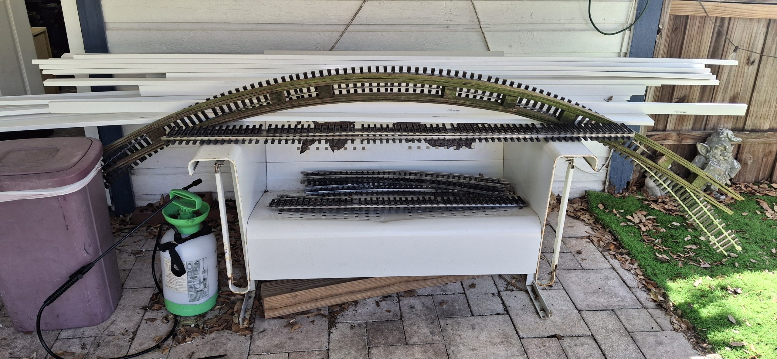
Welcome back to planet Unobtanium! If you thought finding Aristo-craft #6 or wye switches was difficult, or anything in stainless steel for that matter, good luck finding anything curved. As rare as they are on the prototype, it’s no wonder they’re nonexistent in garden scale. If you know of anyone who makes them, or made them, please leave a comment and let me know!
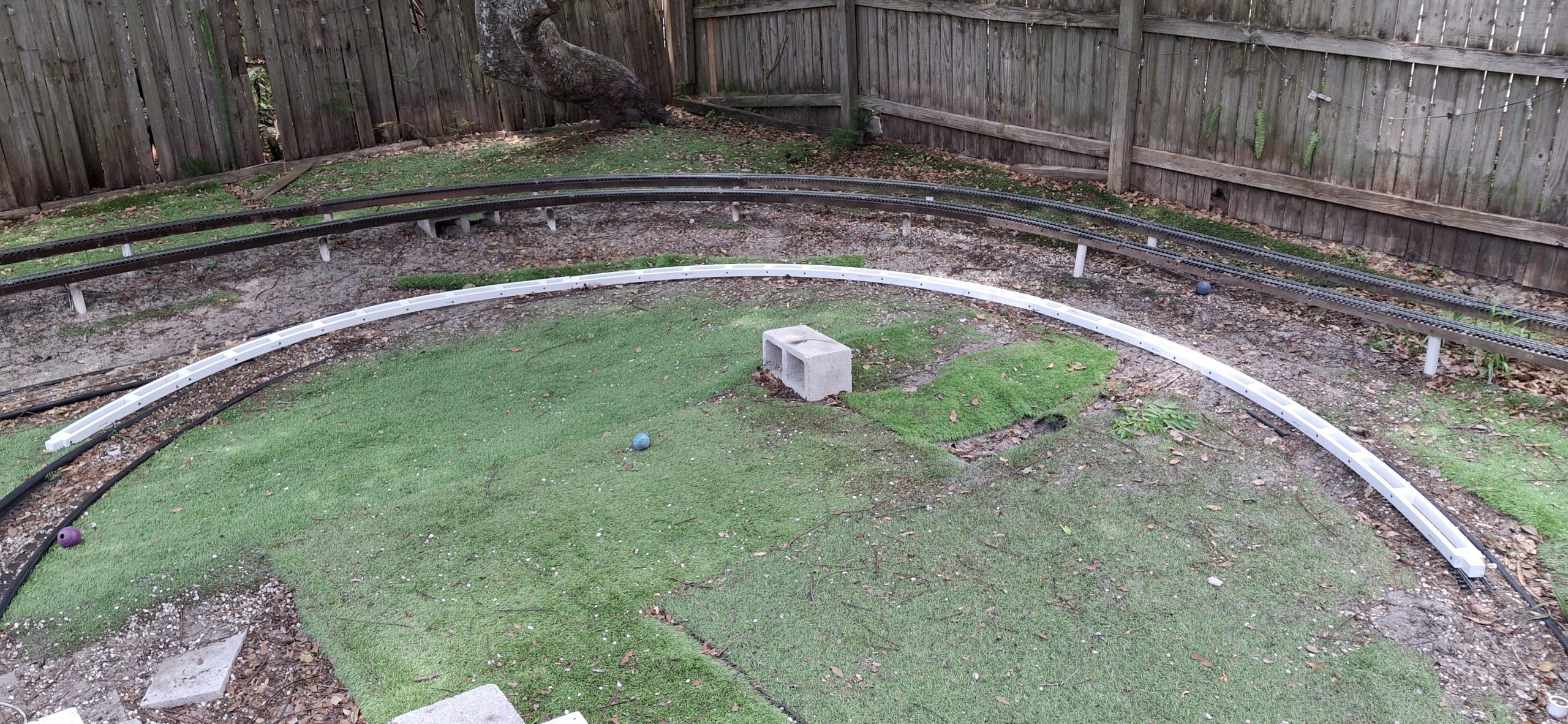
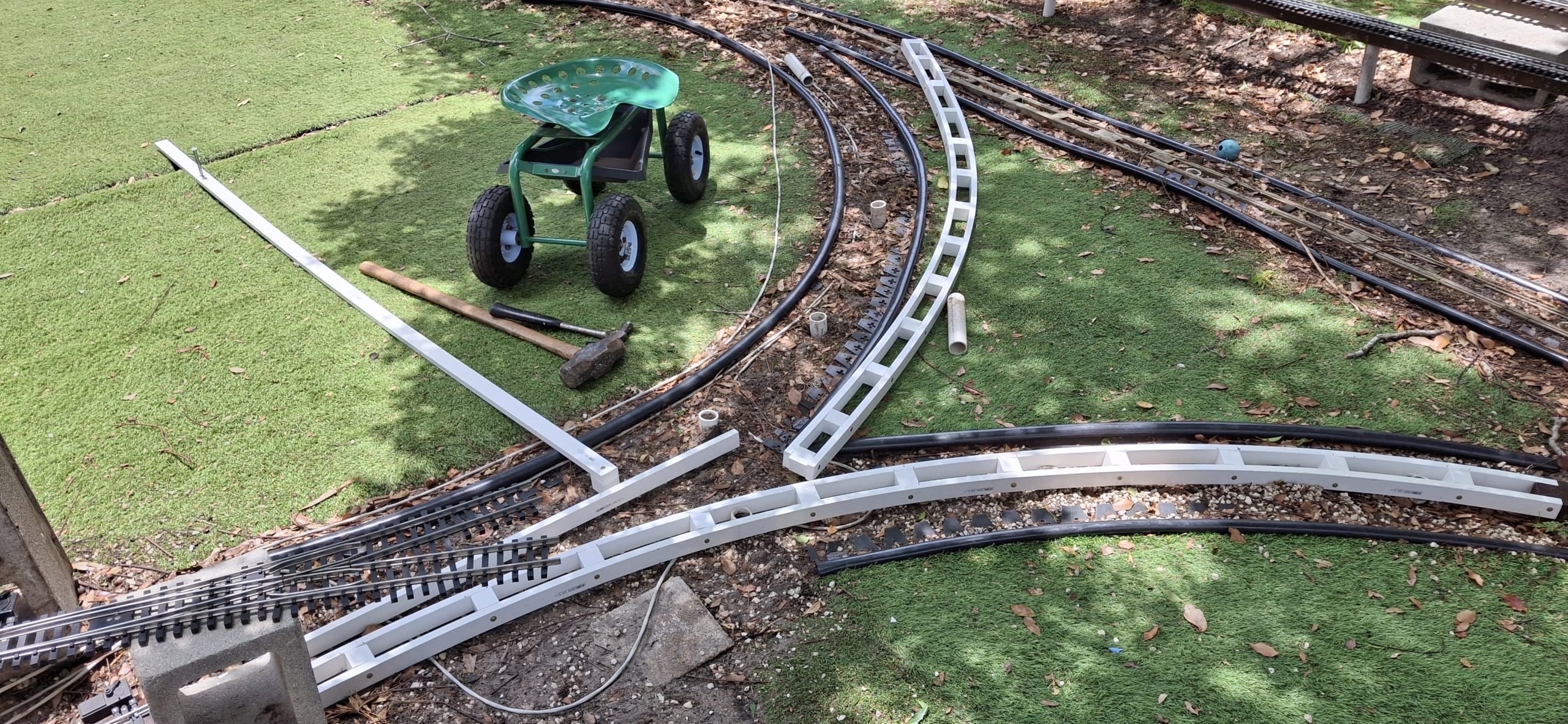
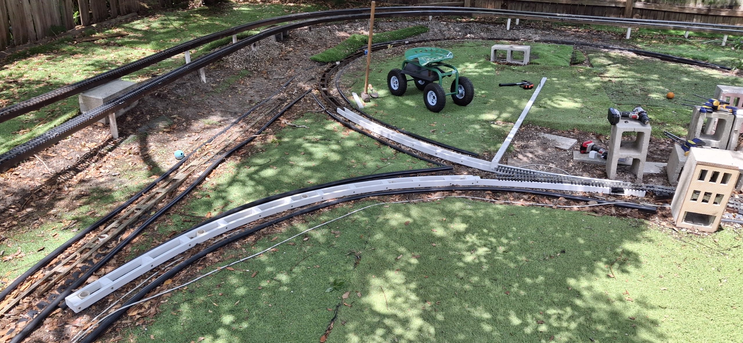
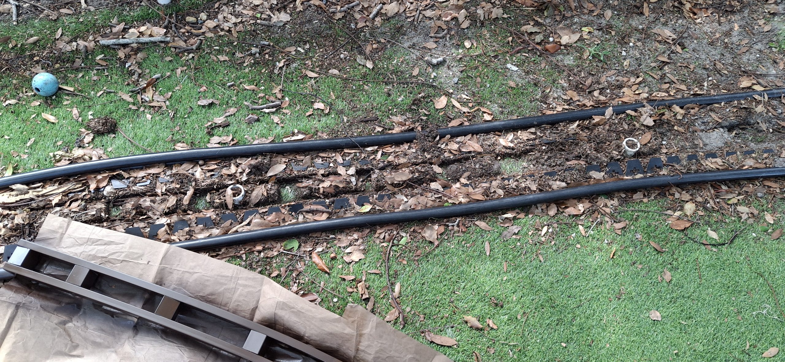
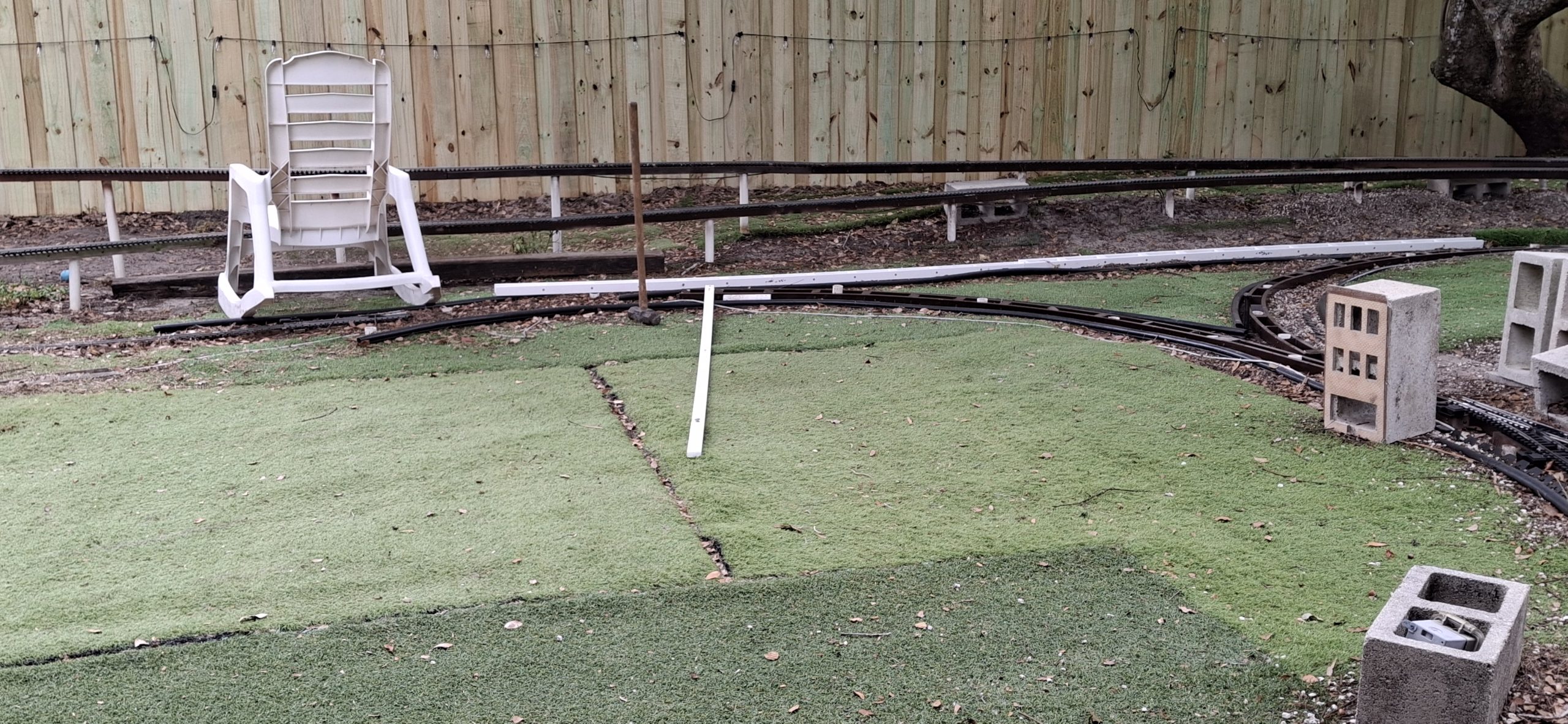
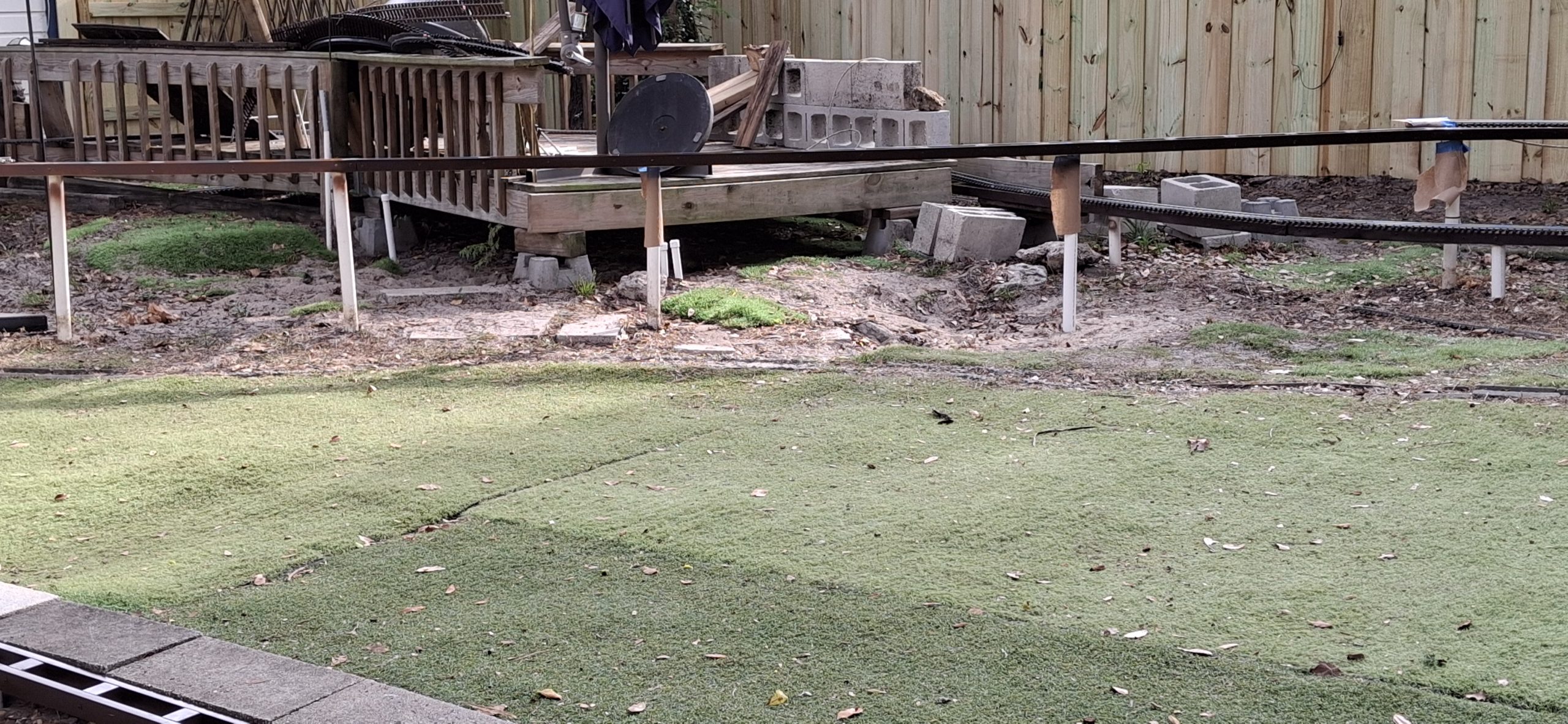
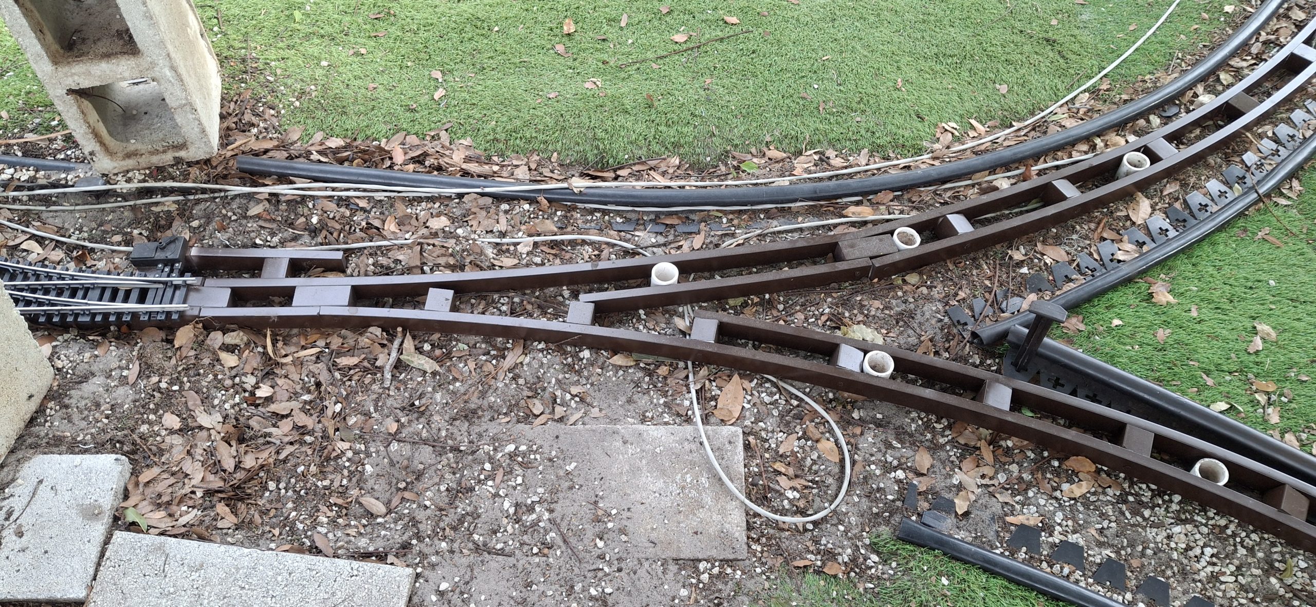
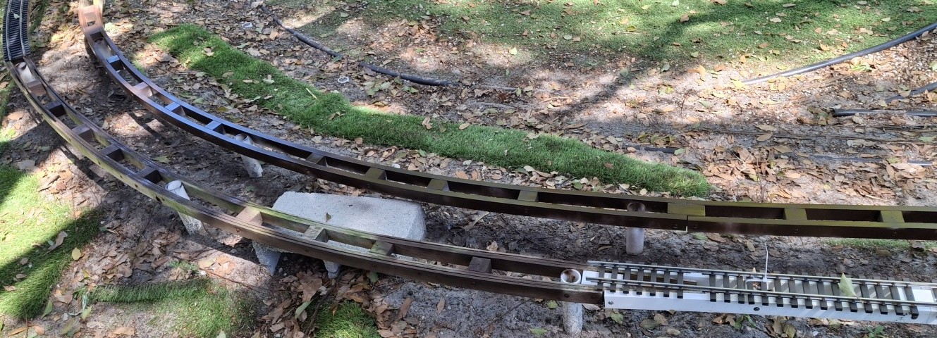
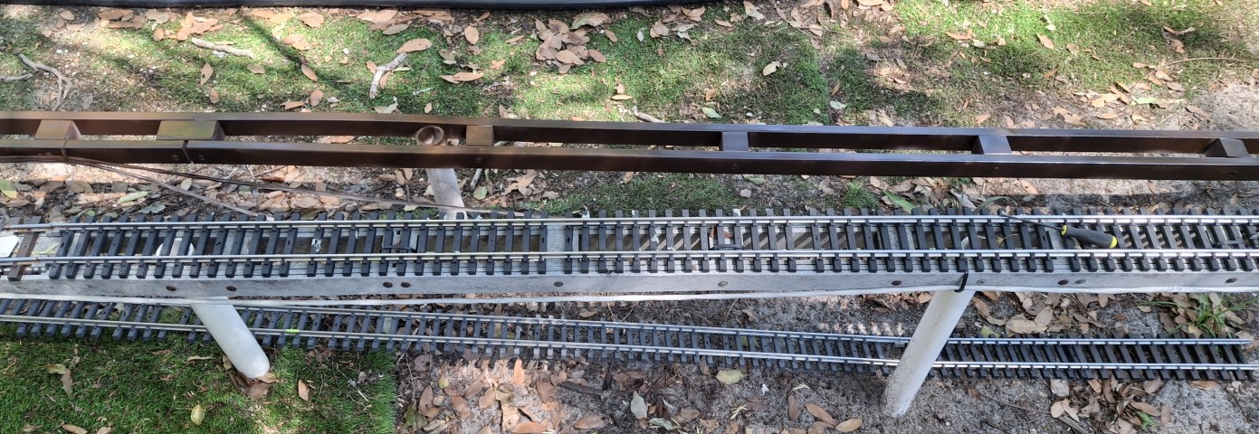
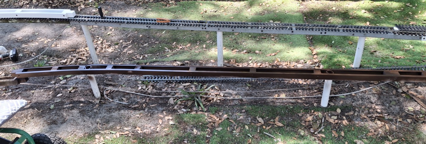
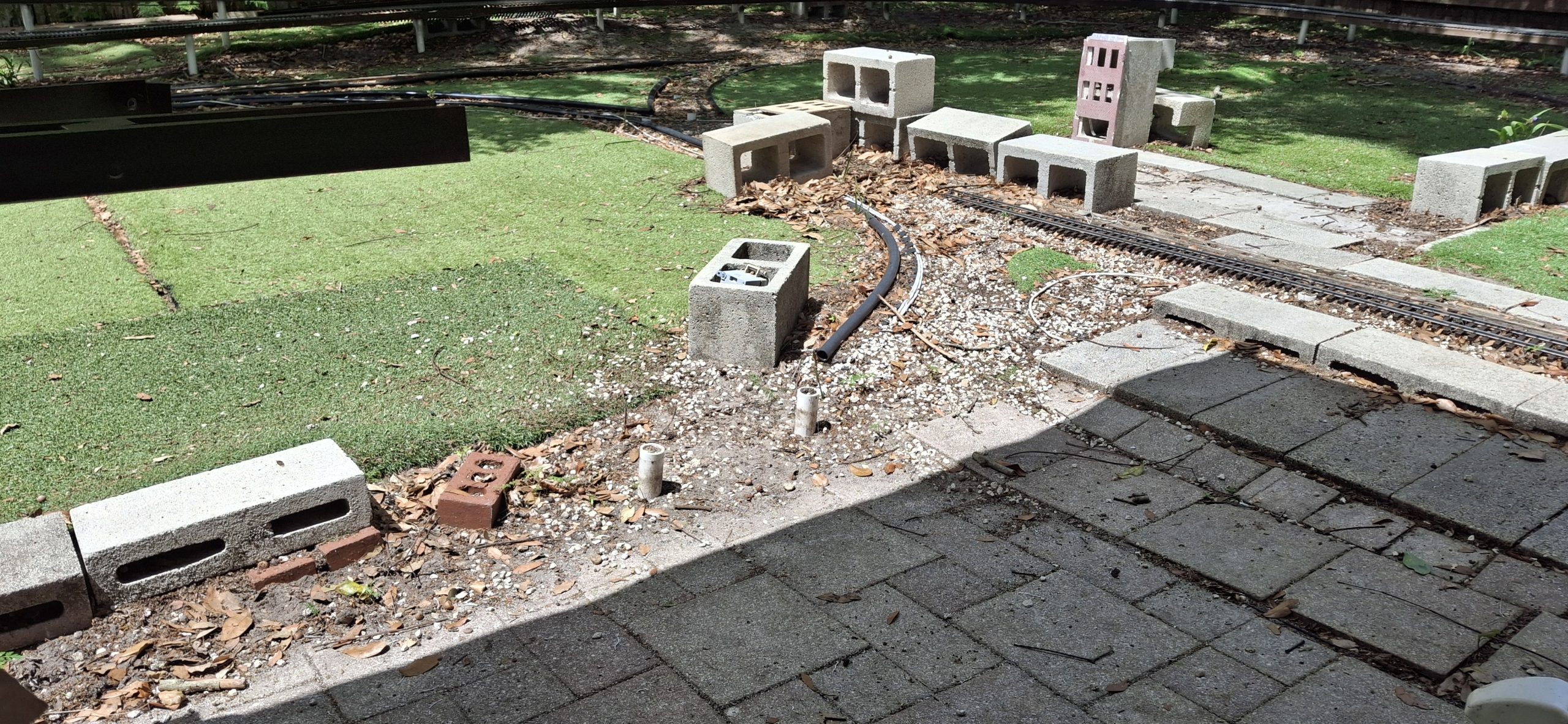
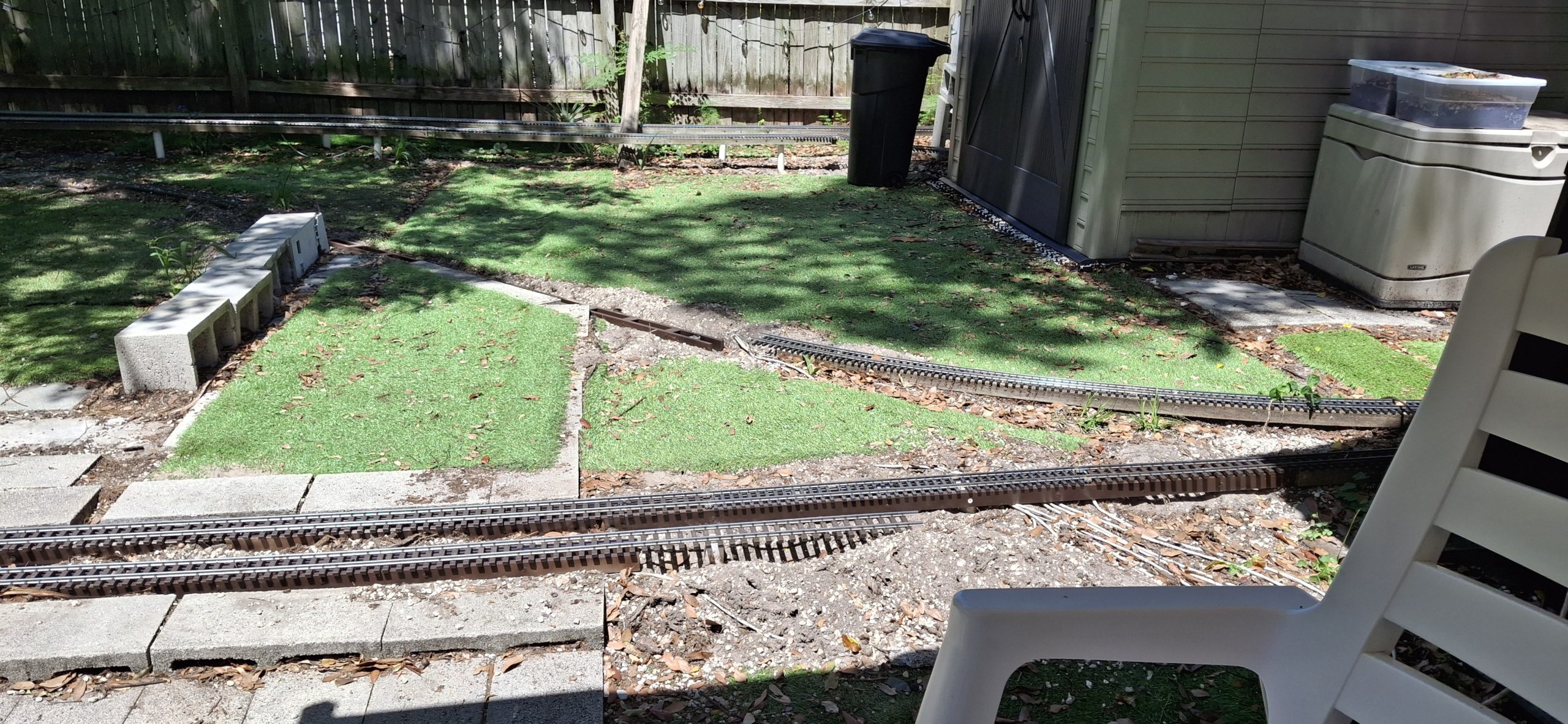
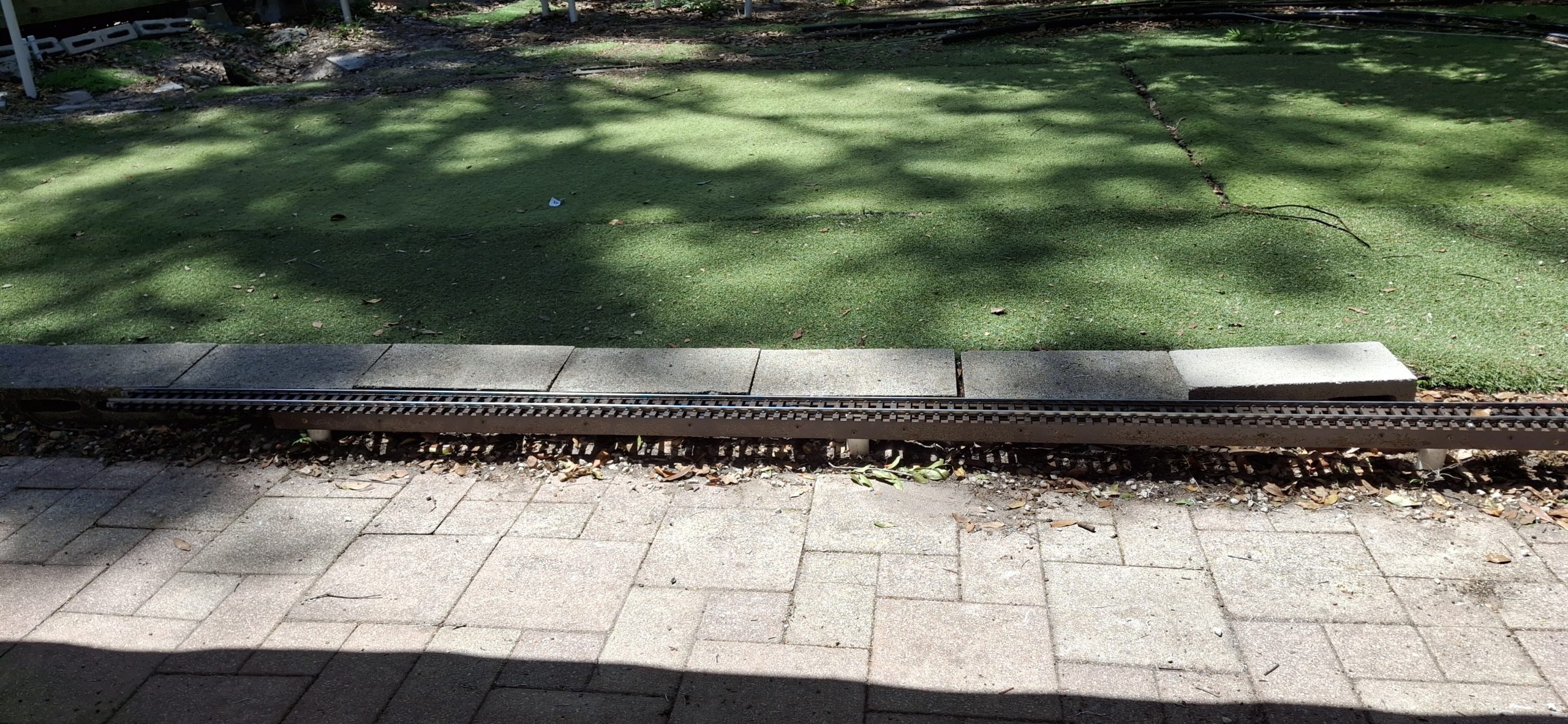
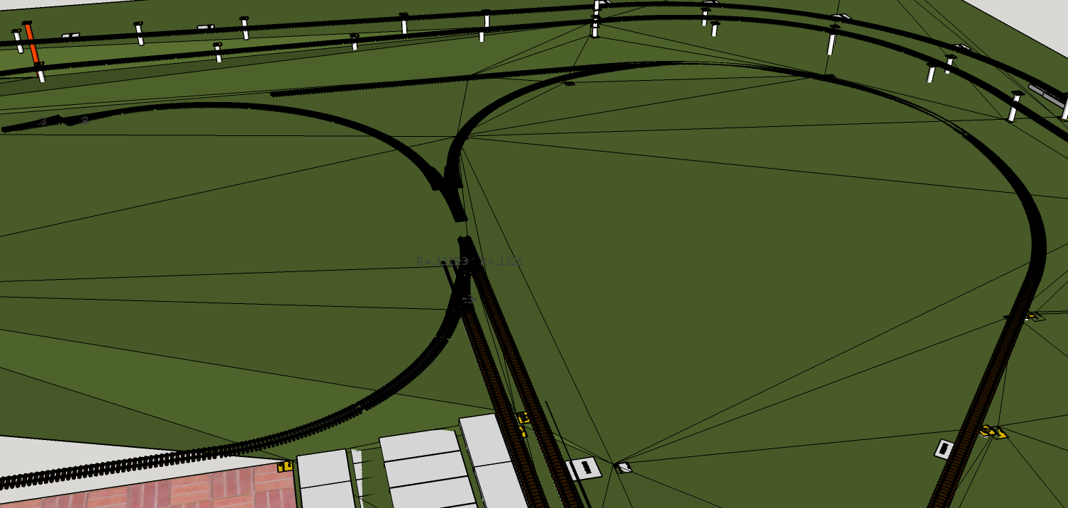
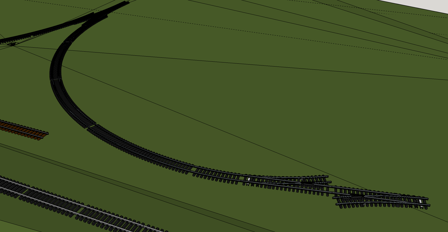
For the longest time I’ve struggled with how to “complete” the downtown wye. Due to space constraints, a standard switch won’t fit. We’ve designed ourselves into a corner, so to speak. In this case, a 14′ diameter semi-circle of track, and a need to escape it at the quarter circle mark to join with the diverging leg of the wye.
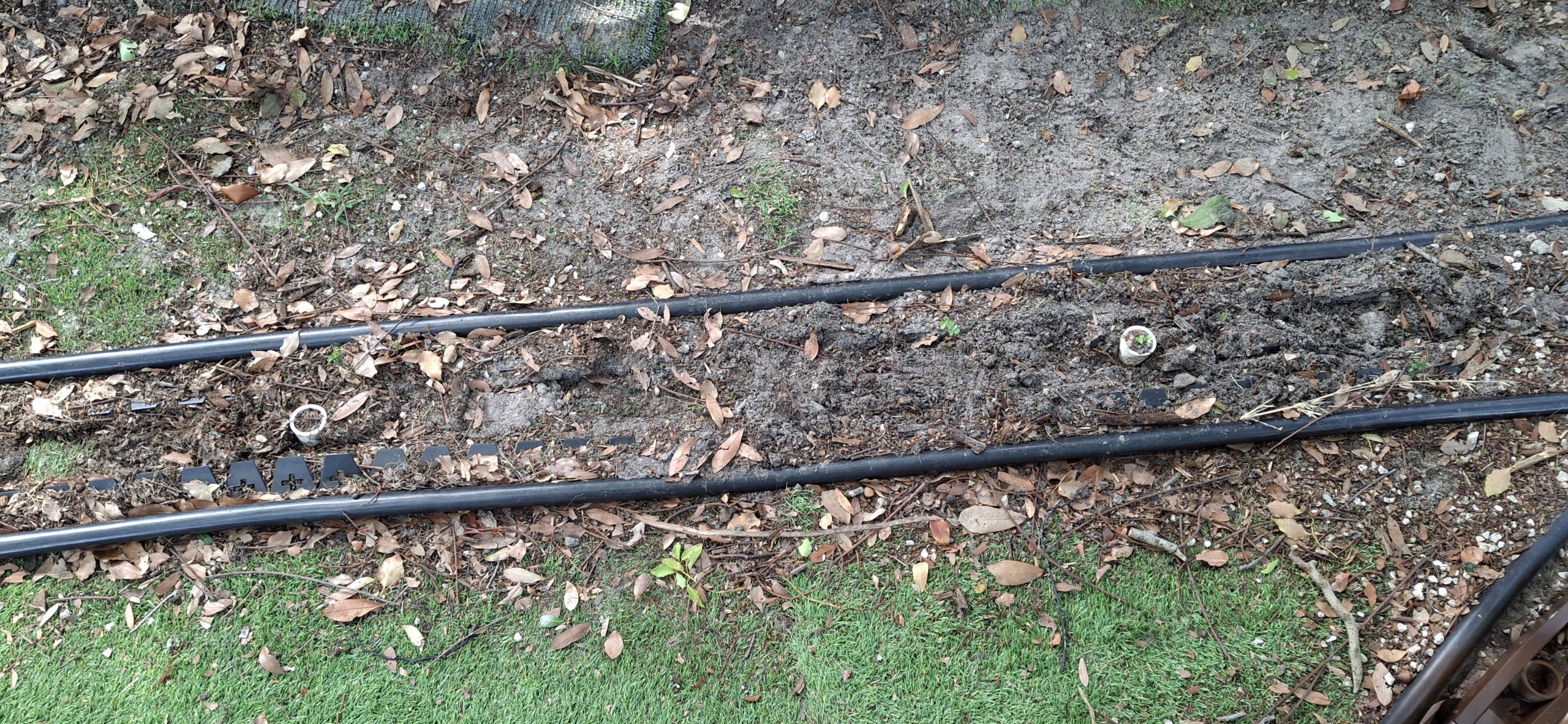
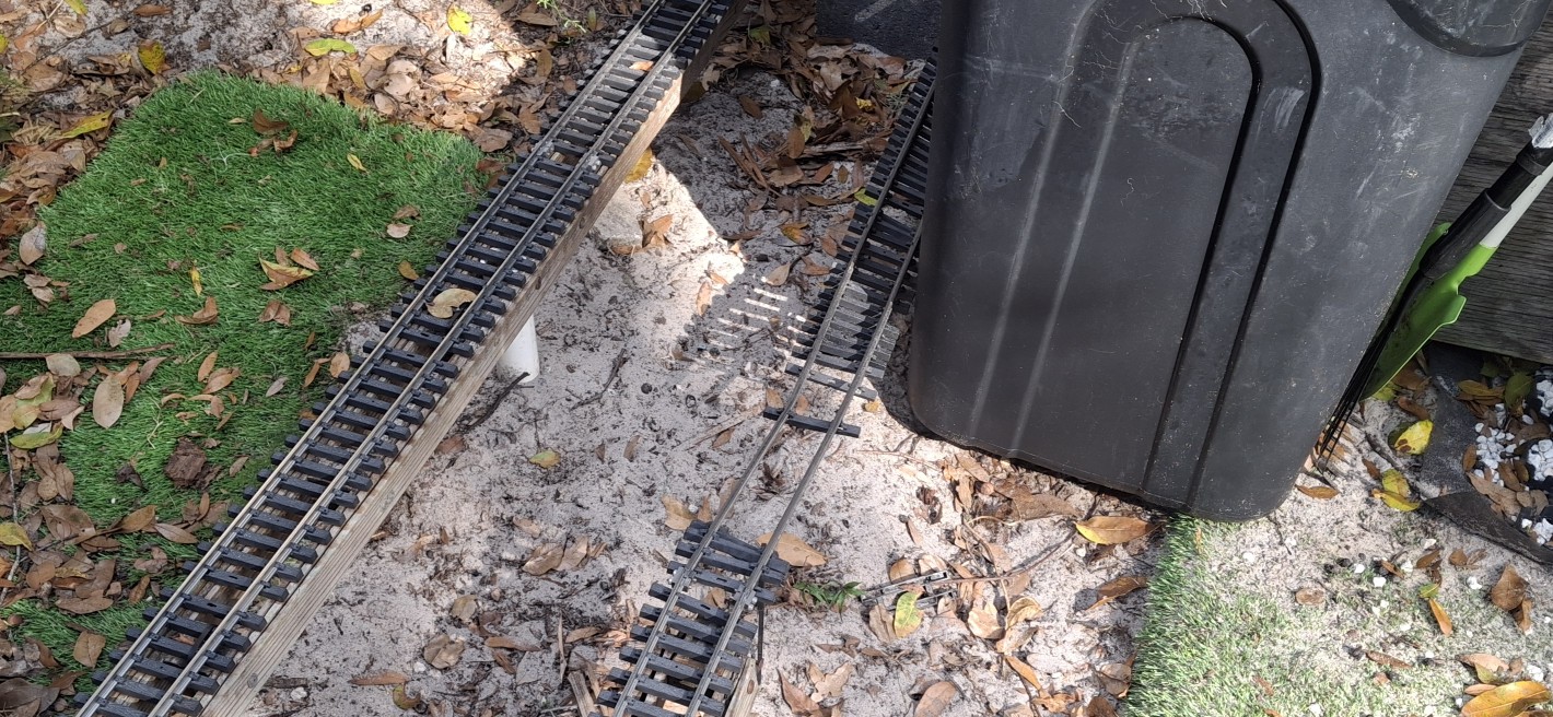
We “cheated” before by replacing one of the 14′ diameter sections of track with a 20′ diameter section, connected directly to the diverging route away from downtown. This left no way to enter the downtown leg of the wye from that direction. That leg was still accessible from the direction of the actual wye switch, but now nothing more than a dead end spur.
Necessity’s A Mother
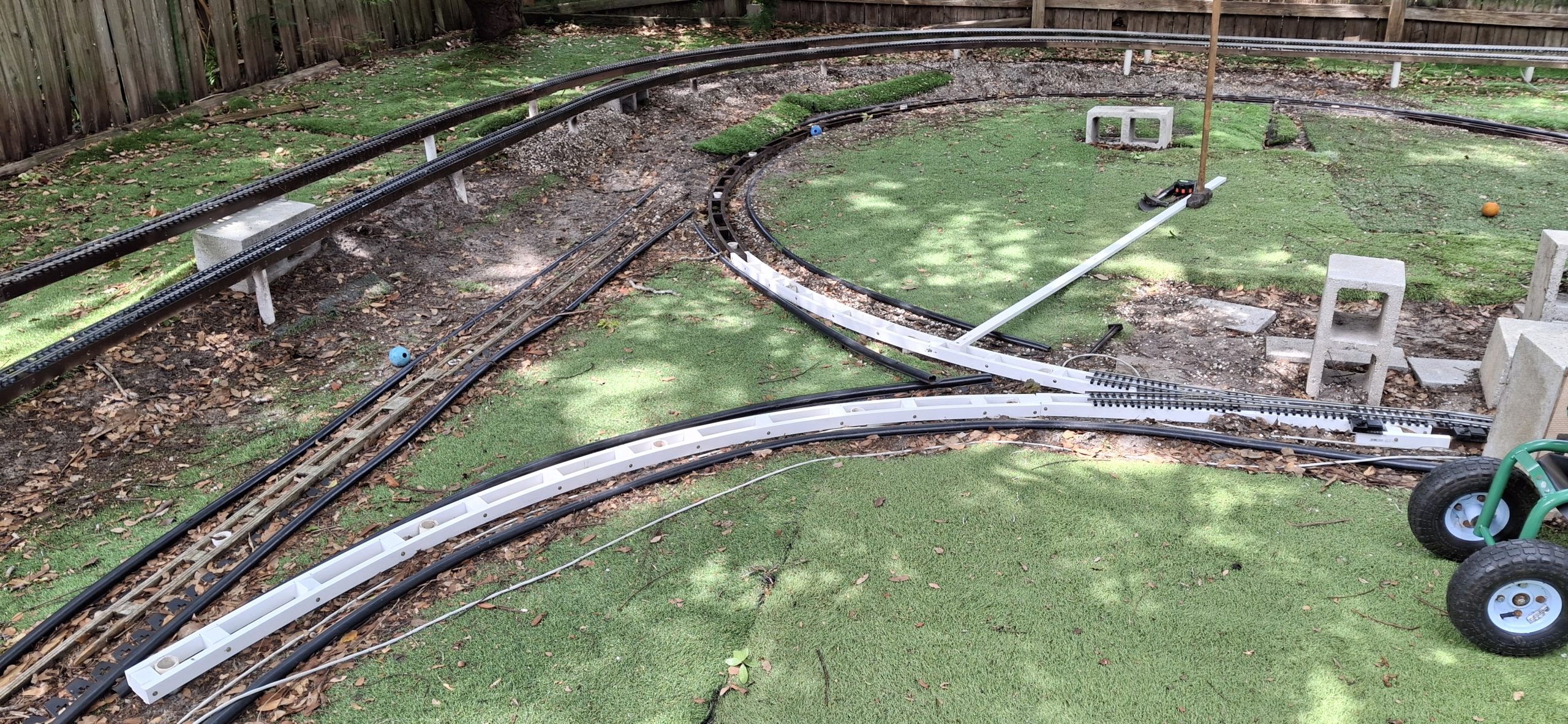
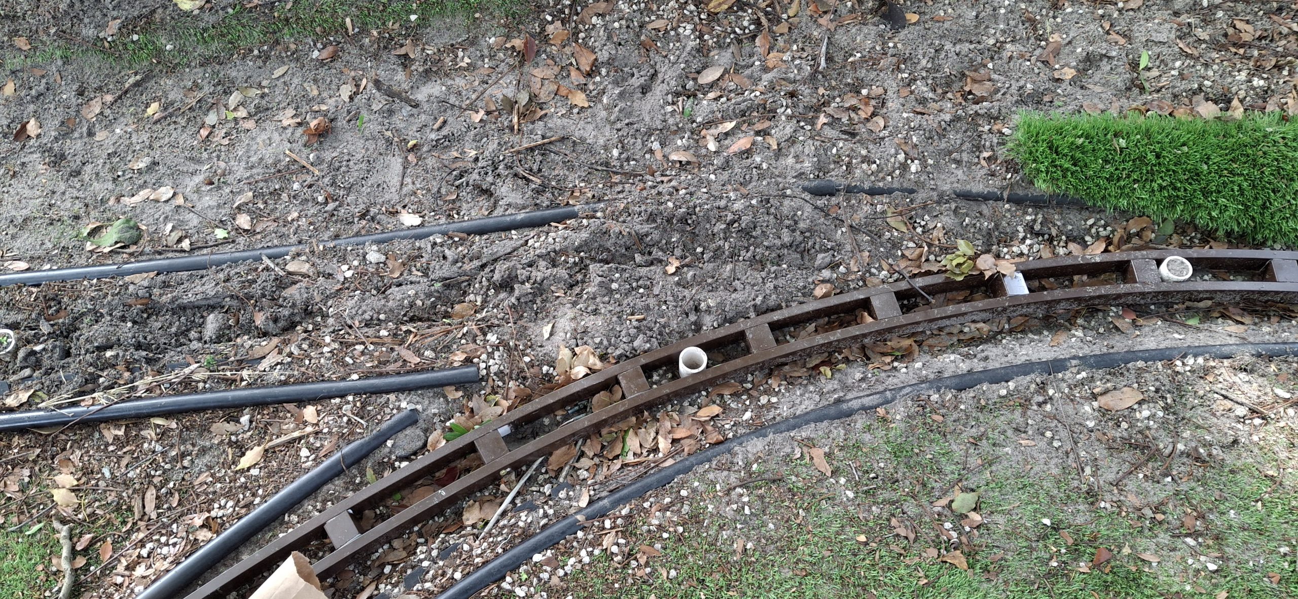
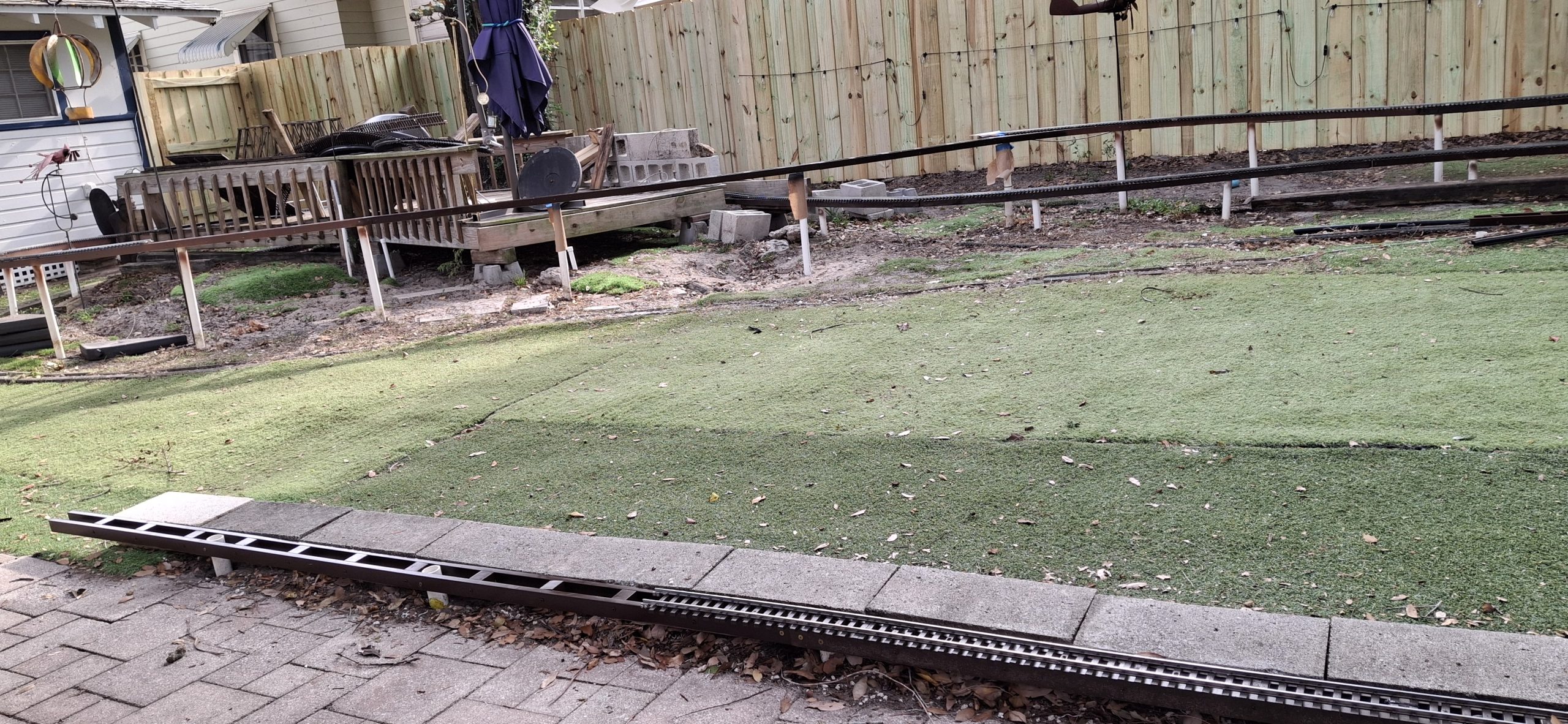
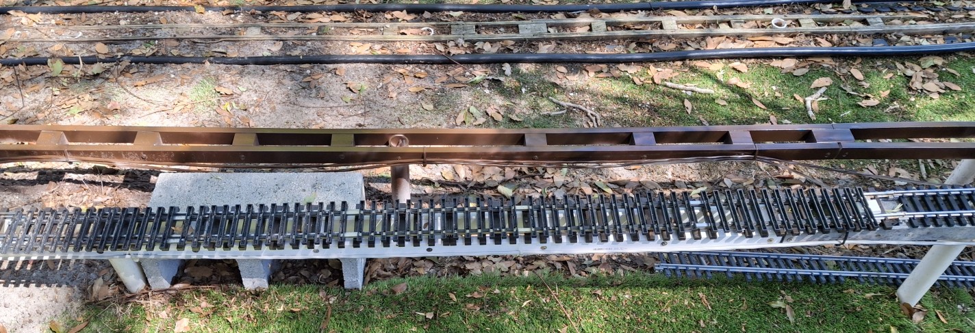
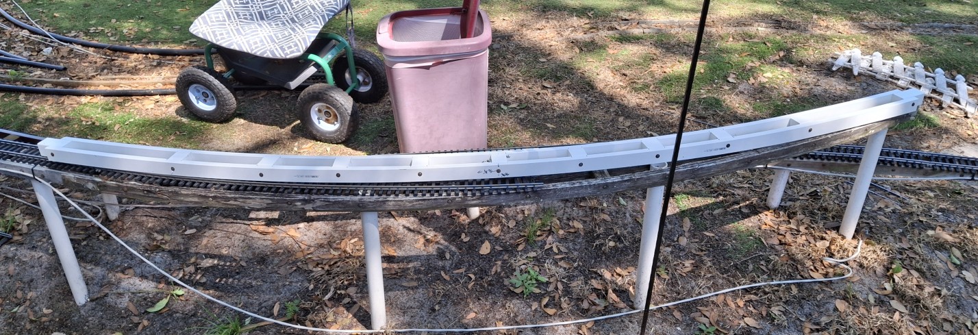
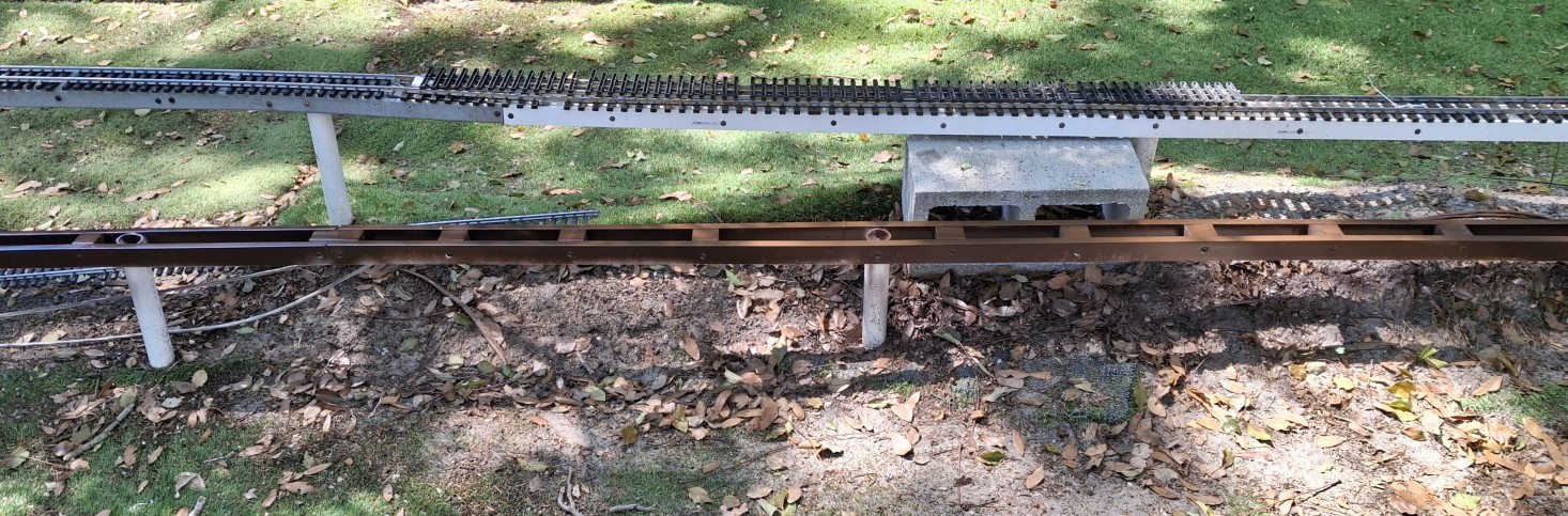
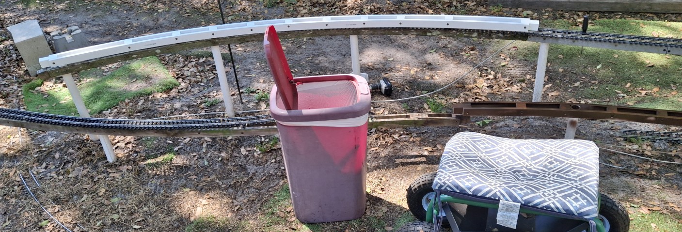
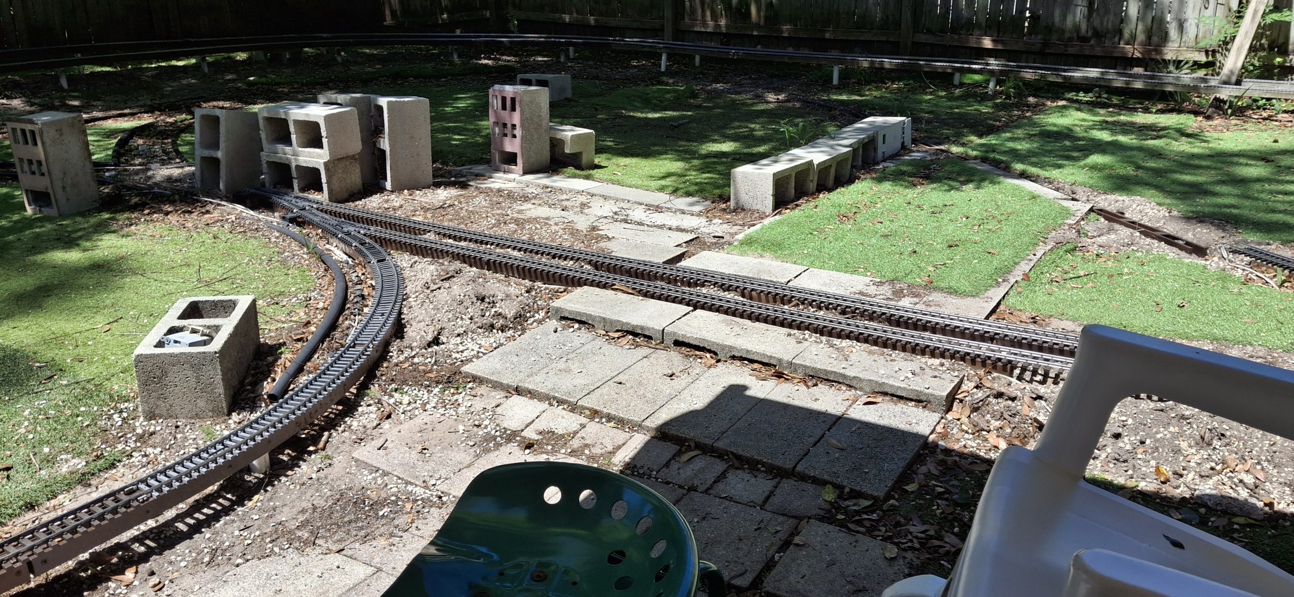
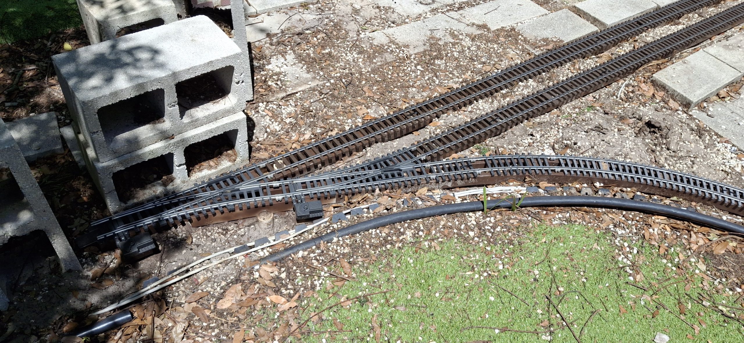
The wye switch was removed as well. The leg into downtown from the south has a wide radius switch, but that was also rearranged to better fit continuous operation. That entire section to the south leads to the lower loop around the deck. To avoid the need for a reverse loop controller, automatic or otherwise, the switches are placed “toe-to-toe” rather than “heel-to-heel”.
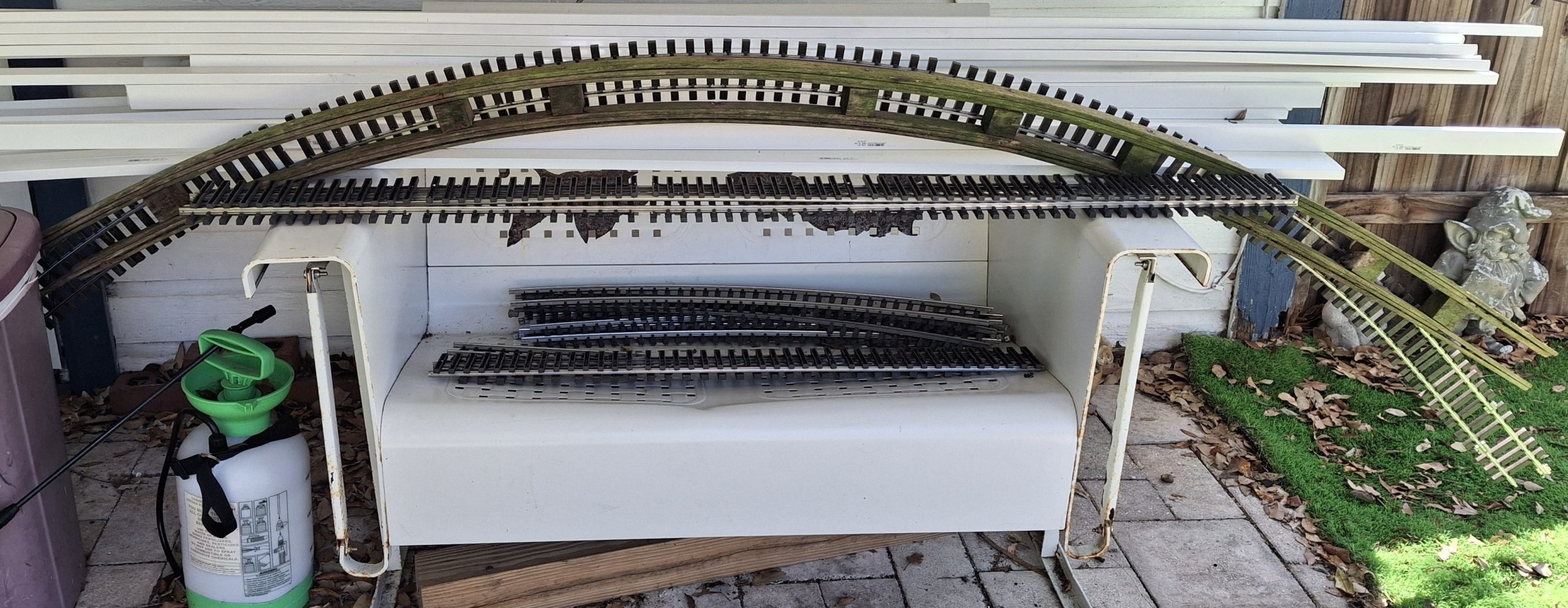
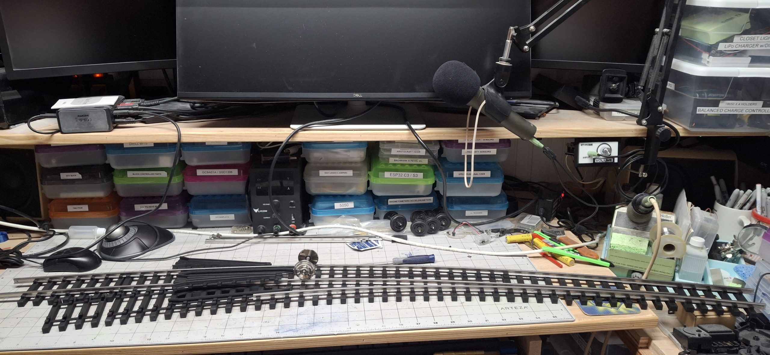
This one’s definitely going to need a picture (or three). I’m waving my hands over here trying to describe it and can already see the blank stares… We’ll get to that shortly. For now, let’s just say we side stepped this issue in favor of continuous running. Eventually we’ll need that auto-reverser, but that’s another project all by itself.
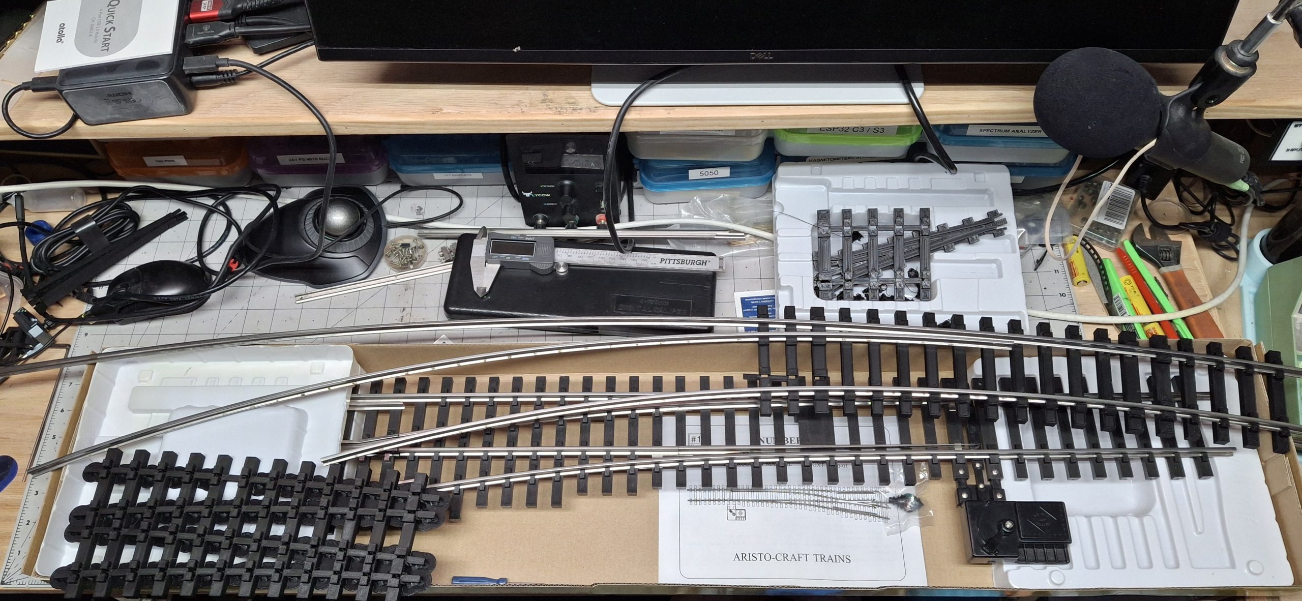
We’ve finally reached the point of needing that curved turnout. Which means it’s time to design one and start making it ourselves. To that end, I resurrected the homemade #5, an old tangent to 14′ diameter switch design I started drafting up ages ago. I shelved it when I realized I was in over my head, still a novice with the SketchUp software and 3D printing.
A New Hope
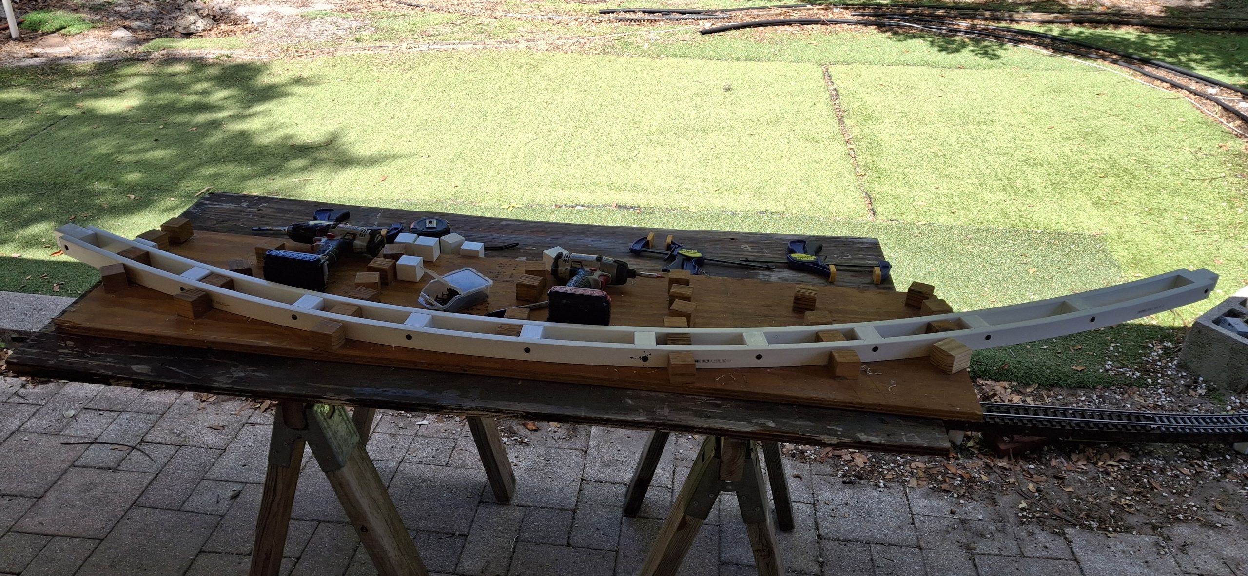
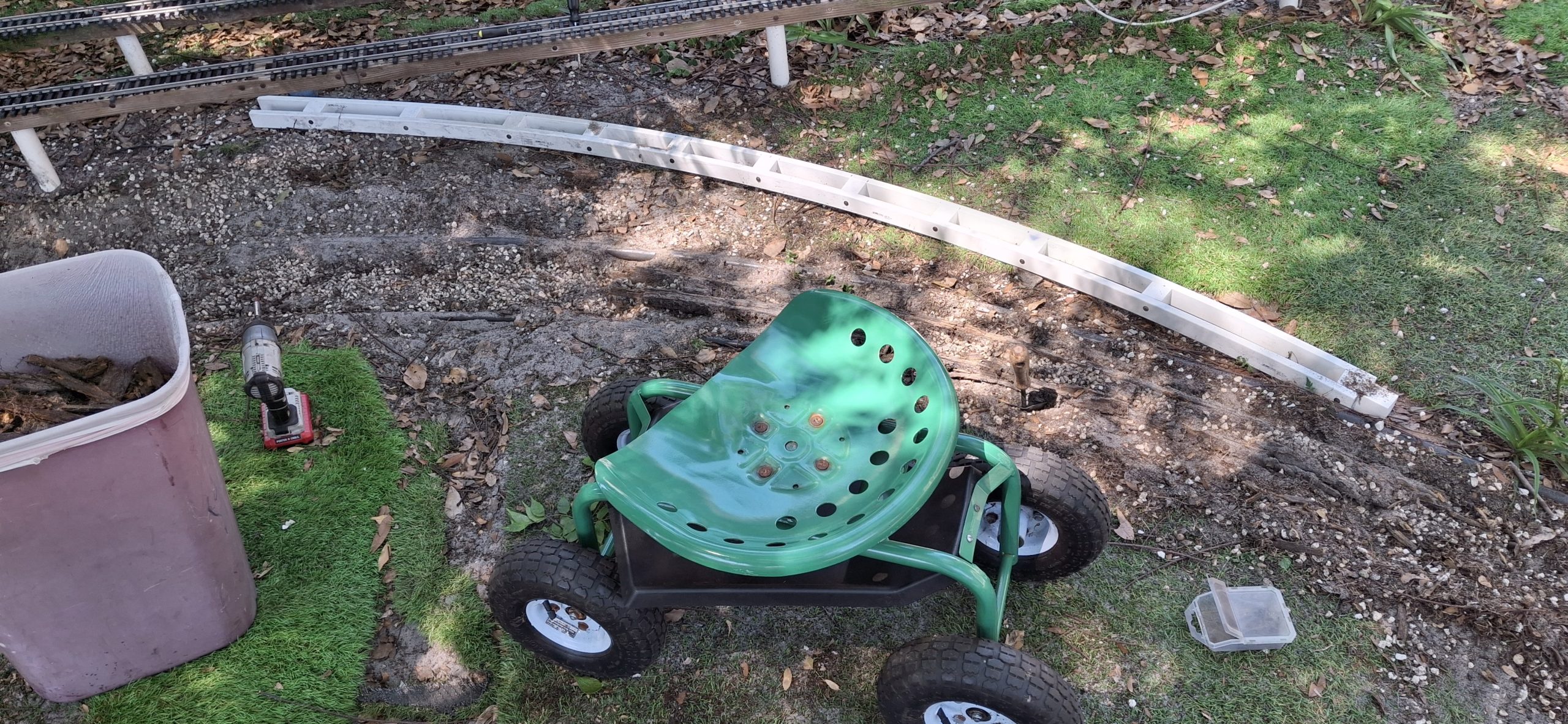
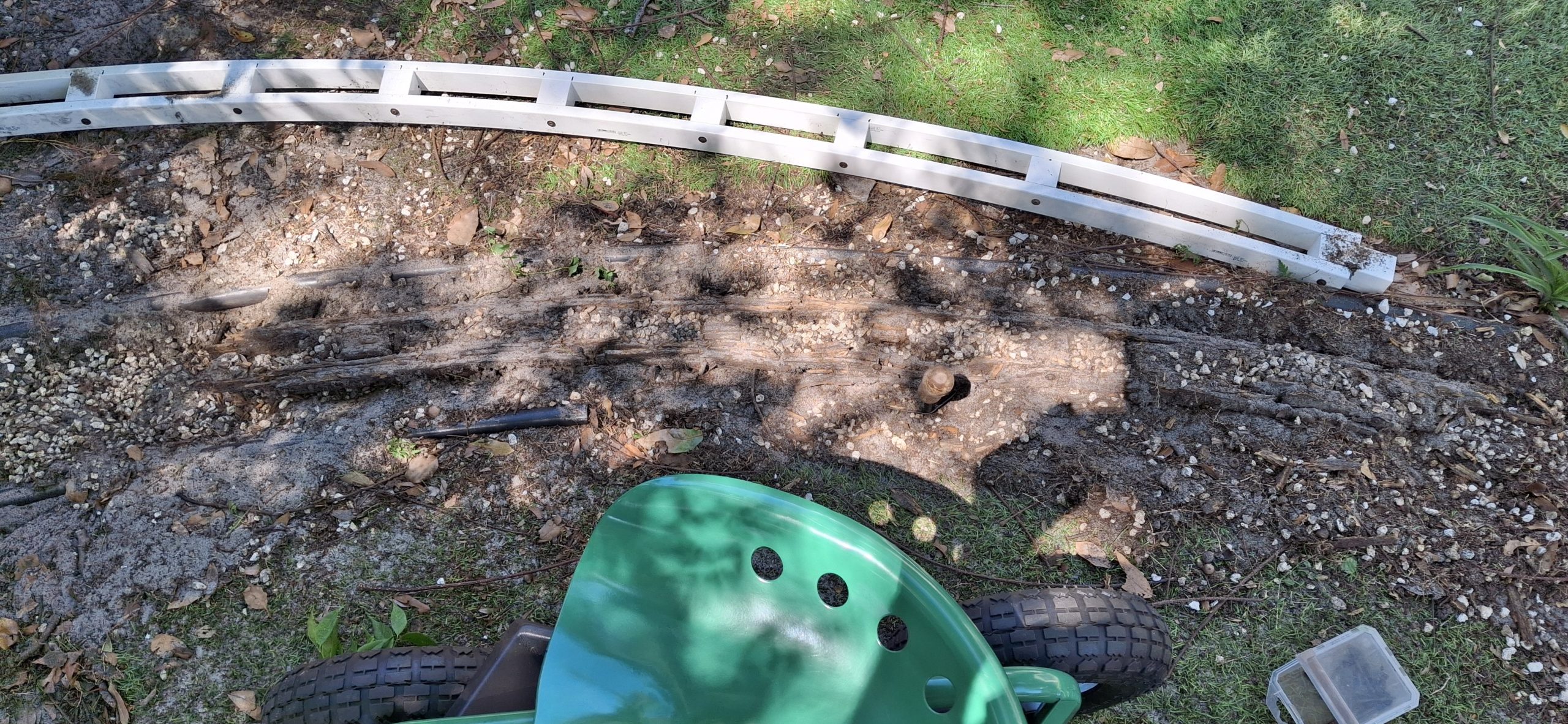
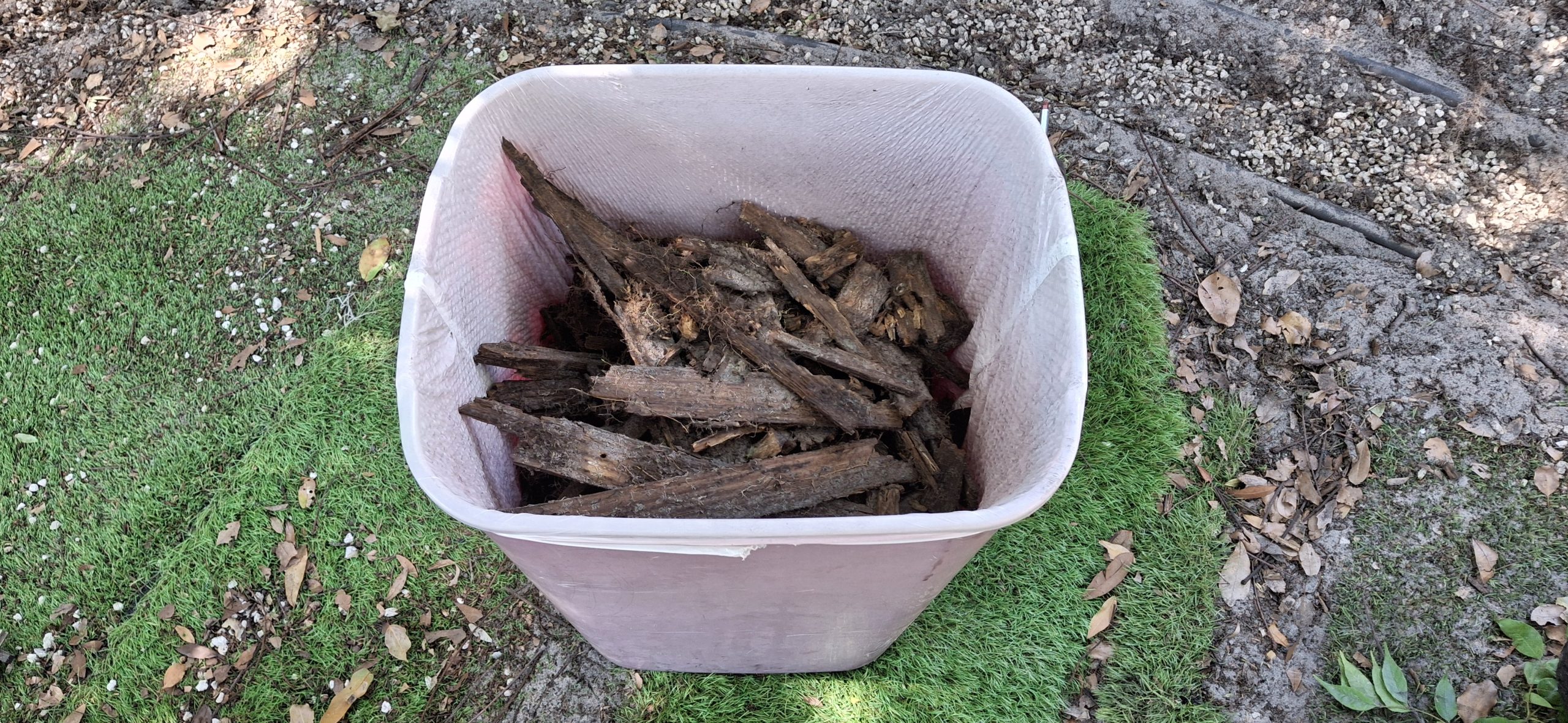
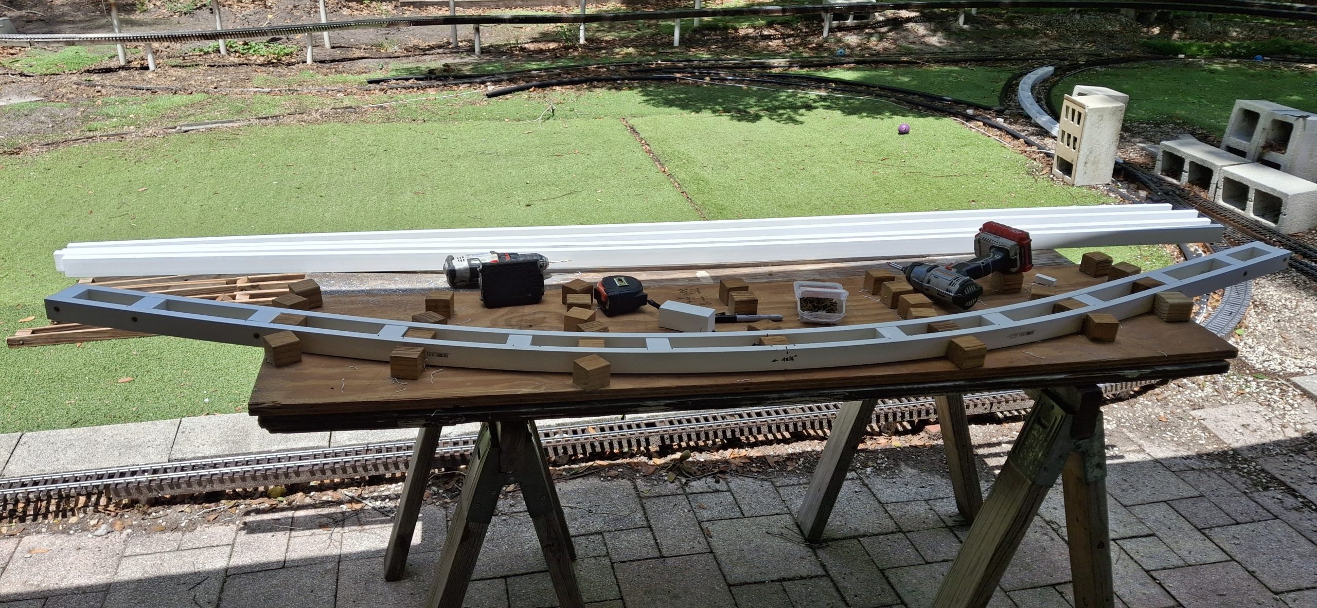
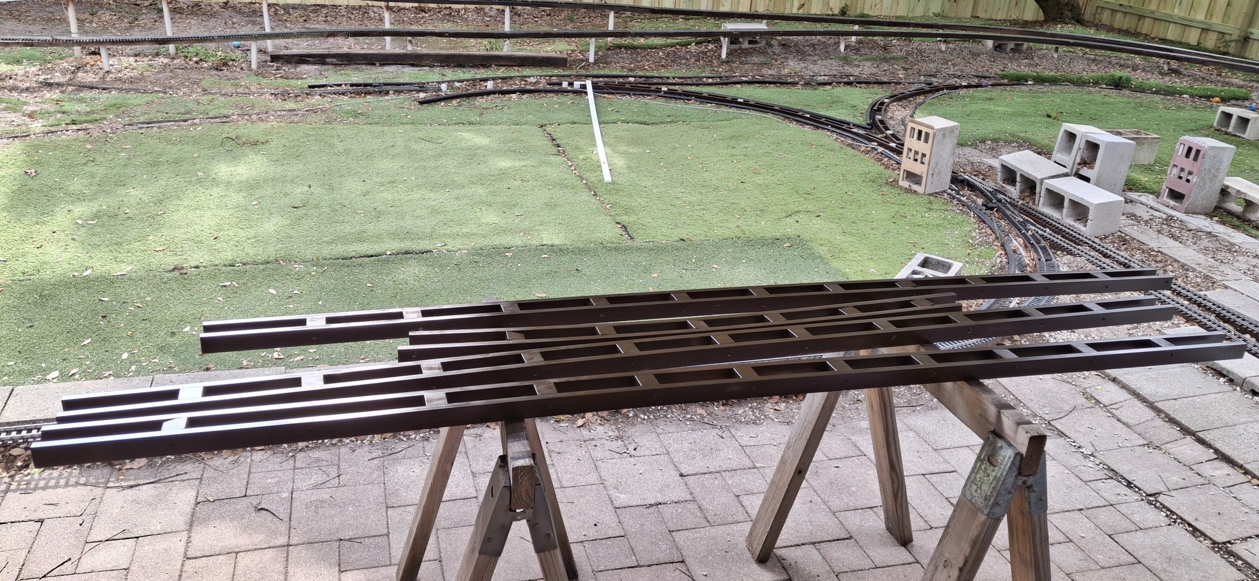
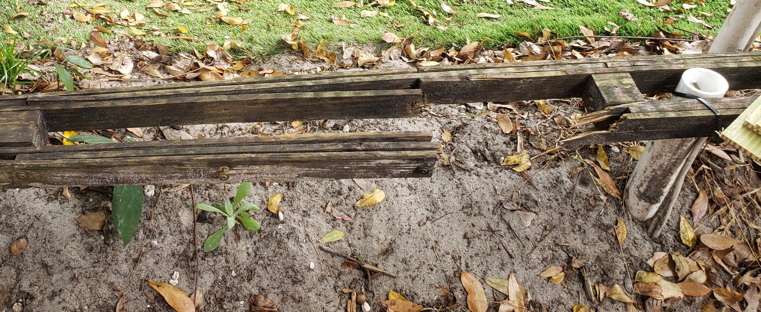
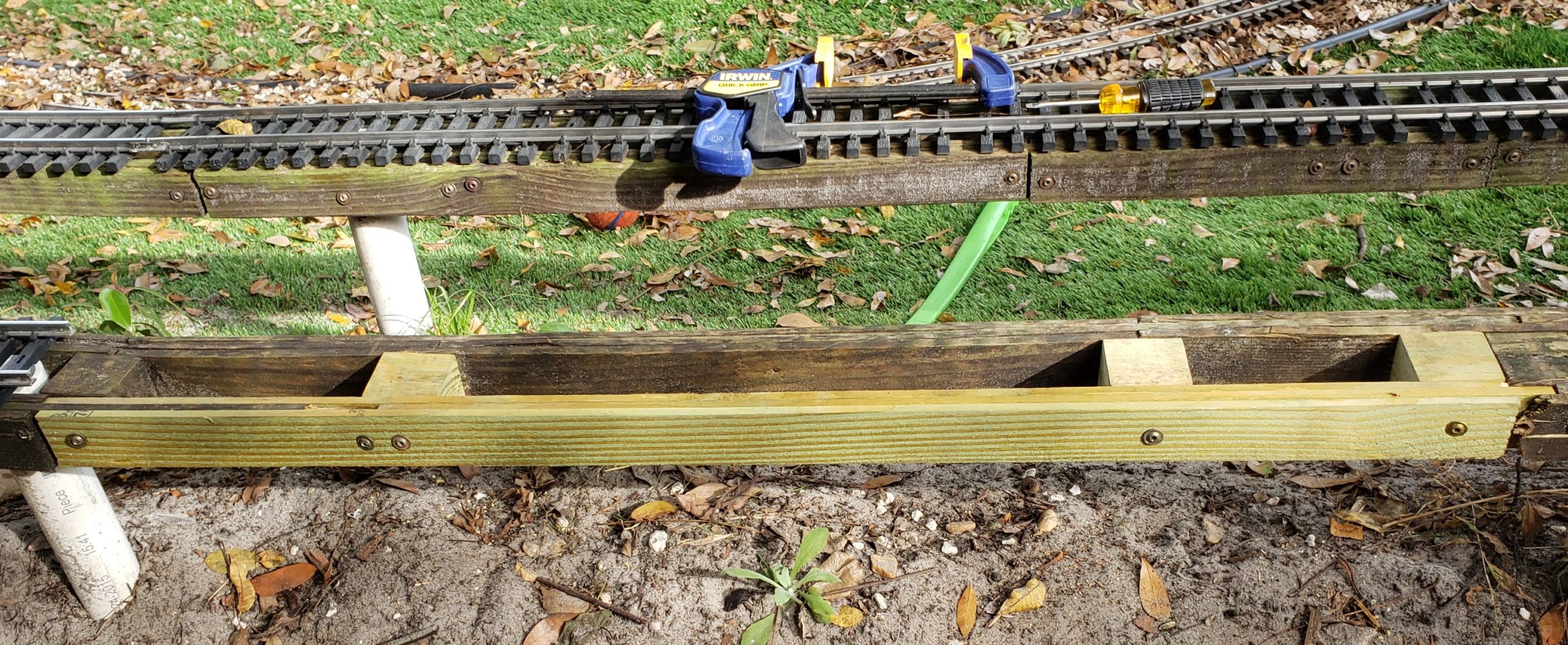
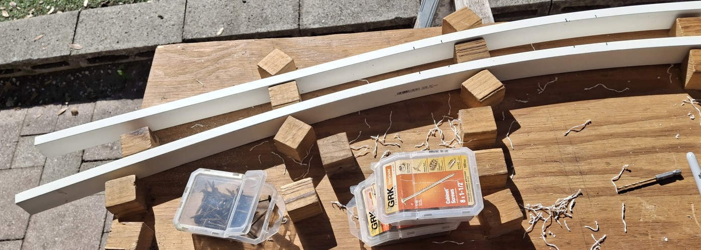
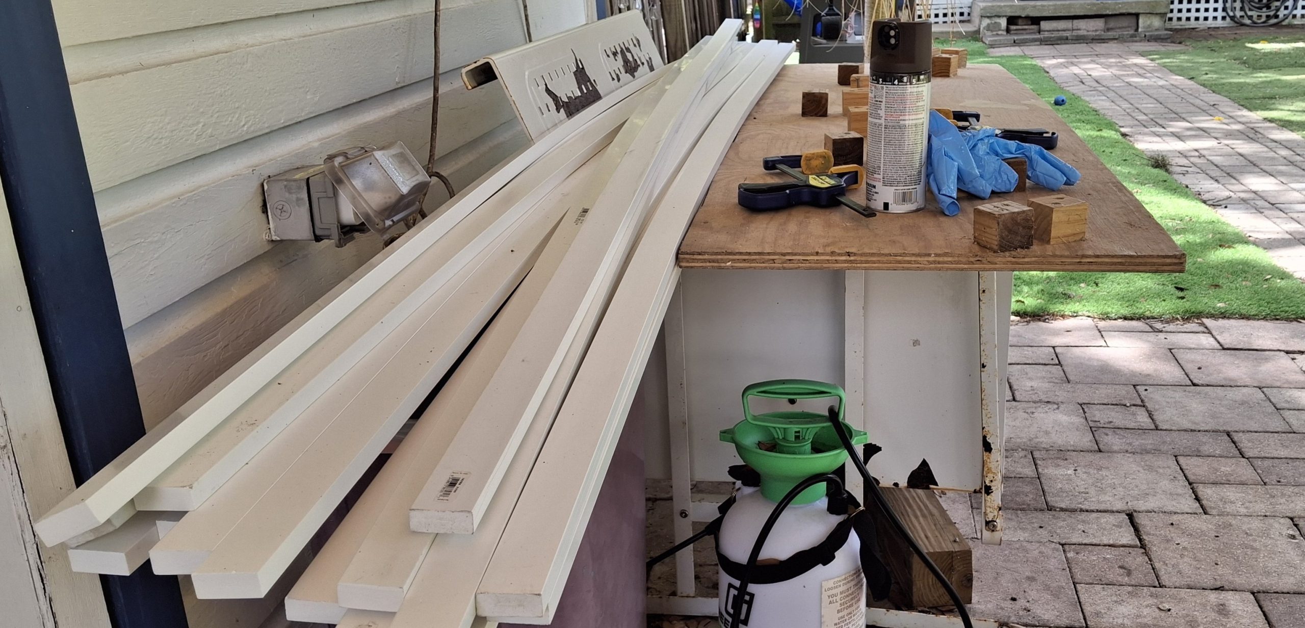
I last touched that design in early March of 2020 and it shows! I’ve gained a lot of experience in those six years though. Now I’m putting it to the test on the homemade curved switch. All my time has been devoted to this new design, when I’m not working on replacing the rotted stringers that is, which means anytime during the week when I’m not working my day job.
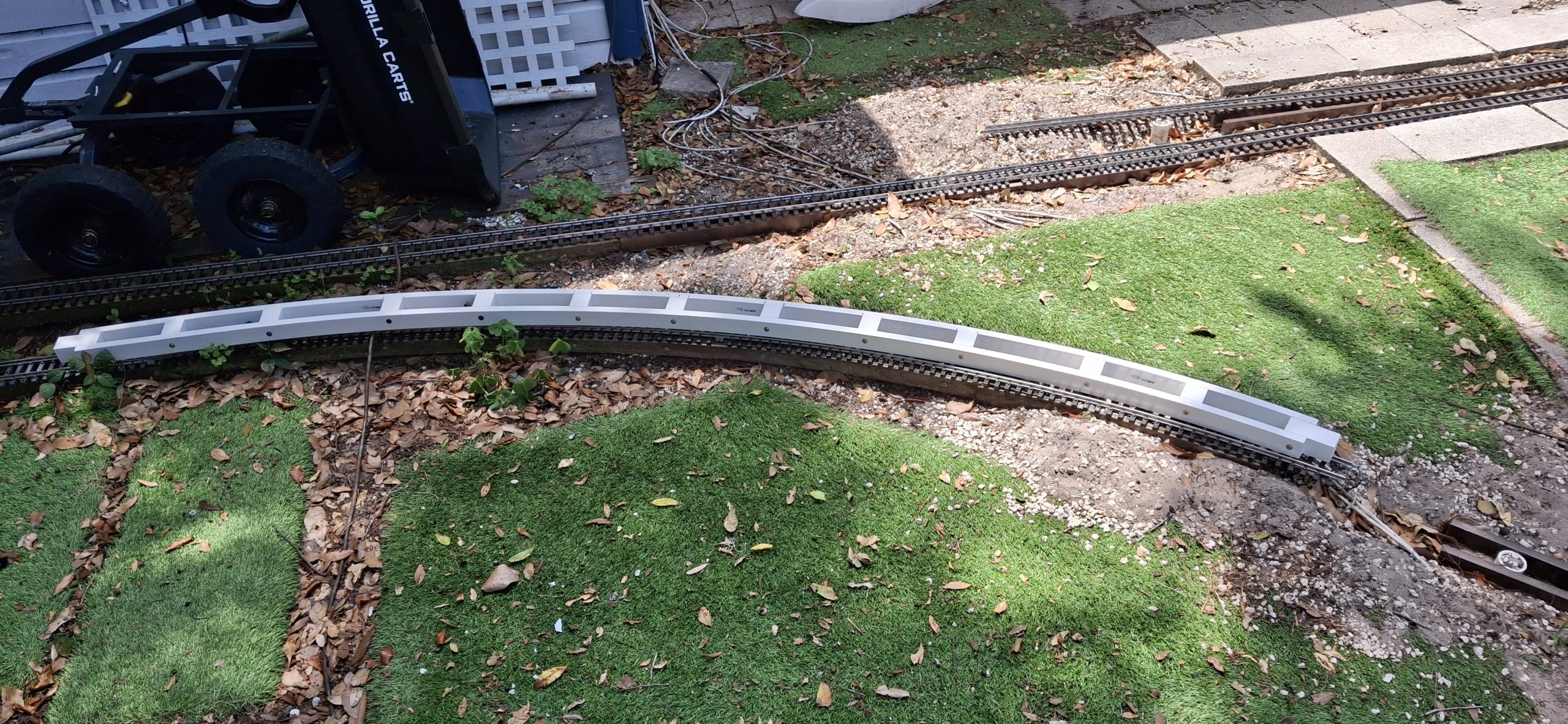
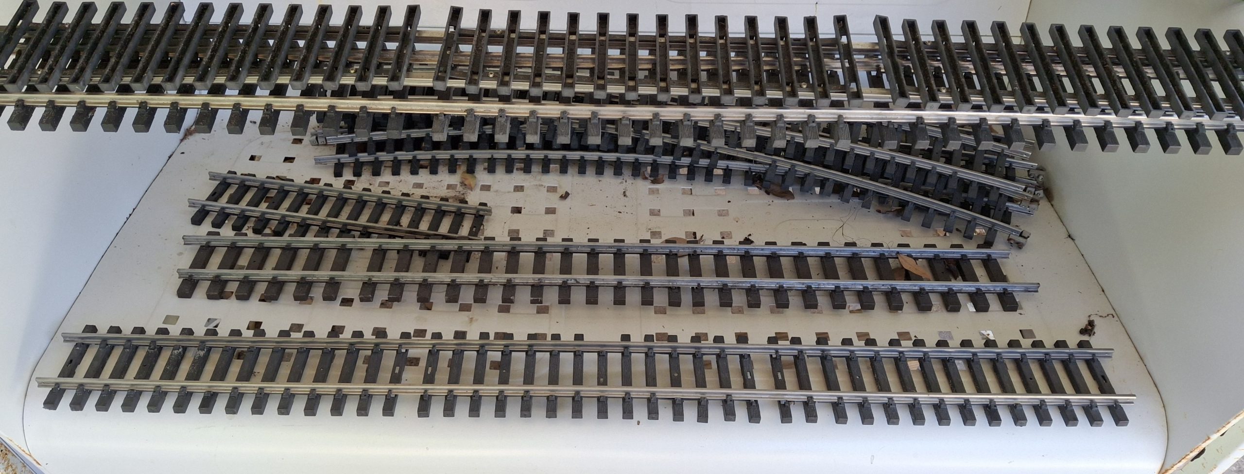
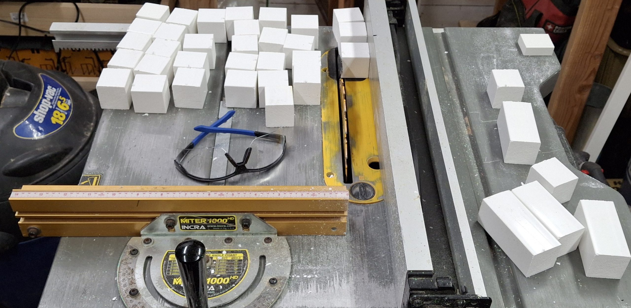
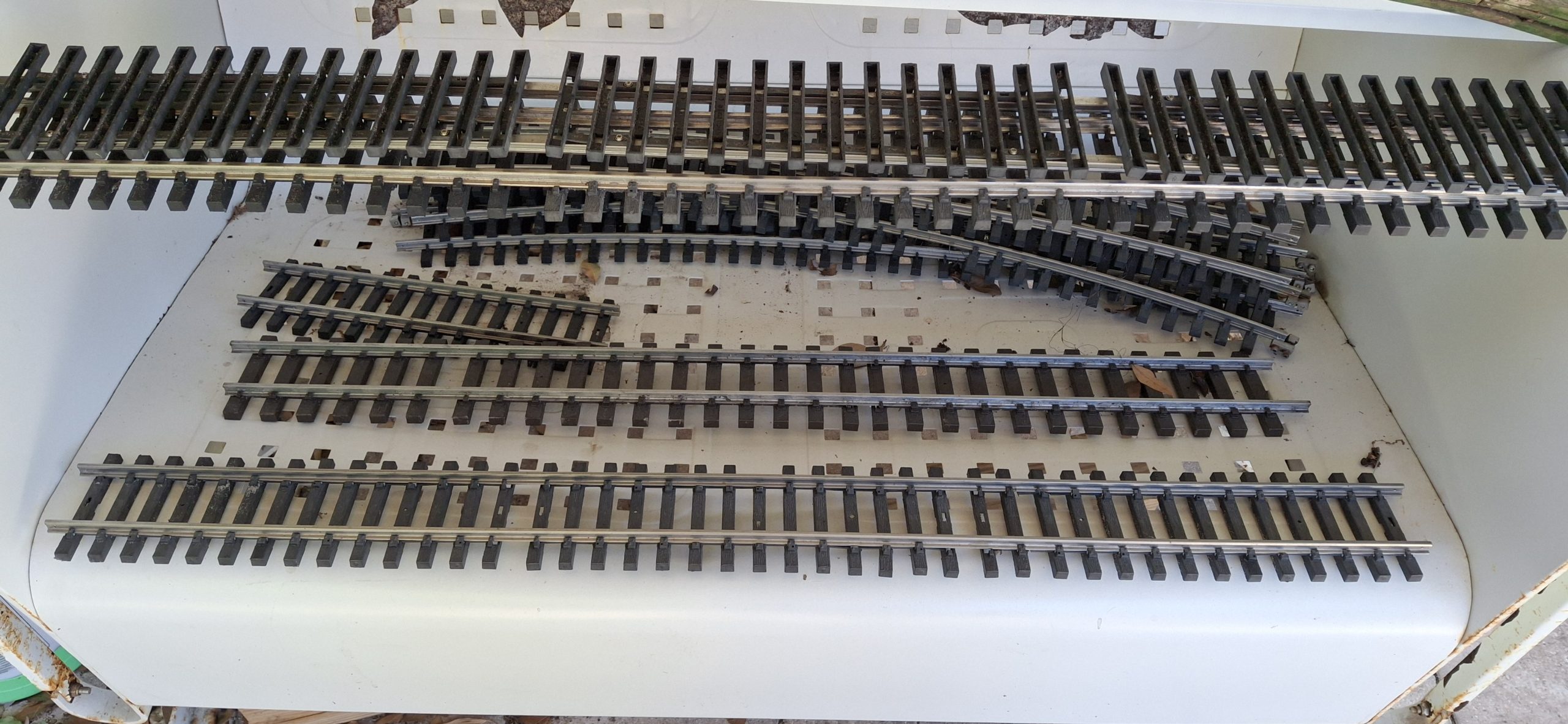
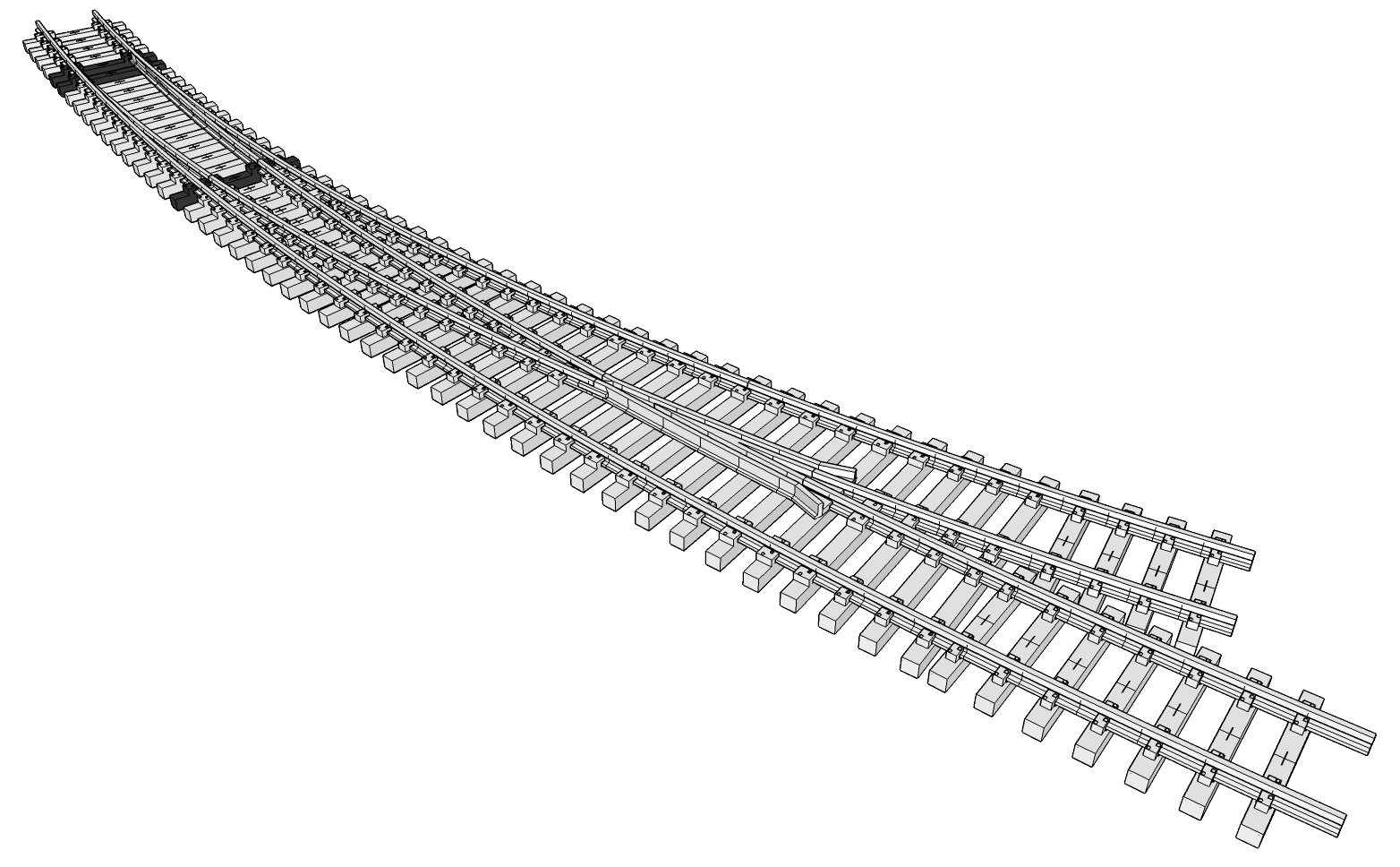
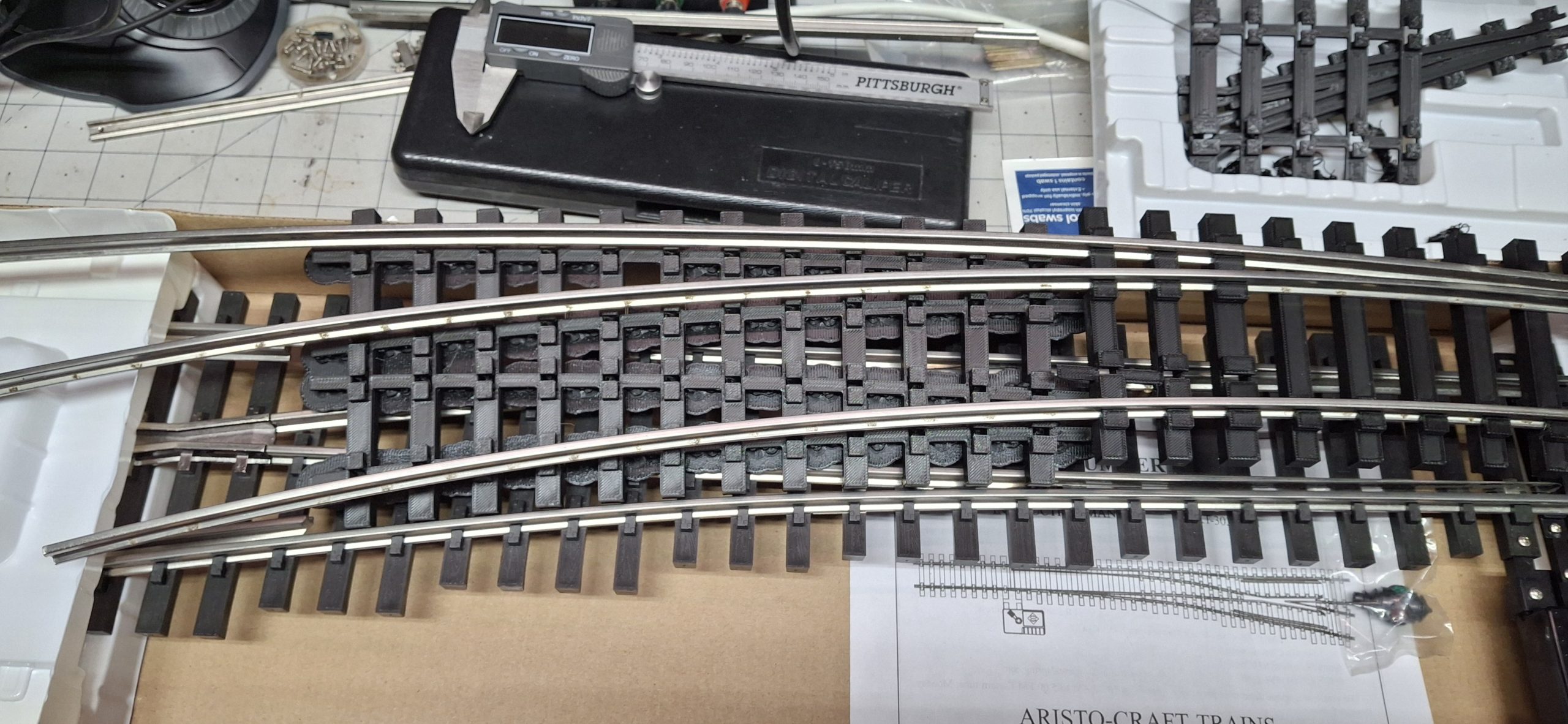
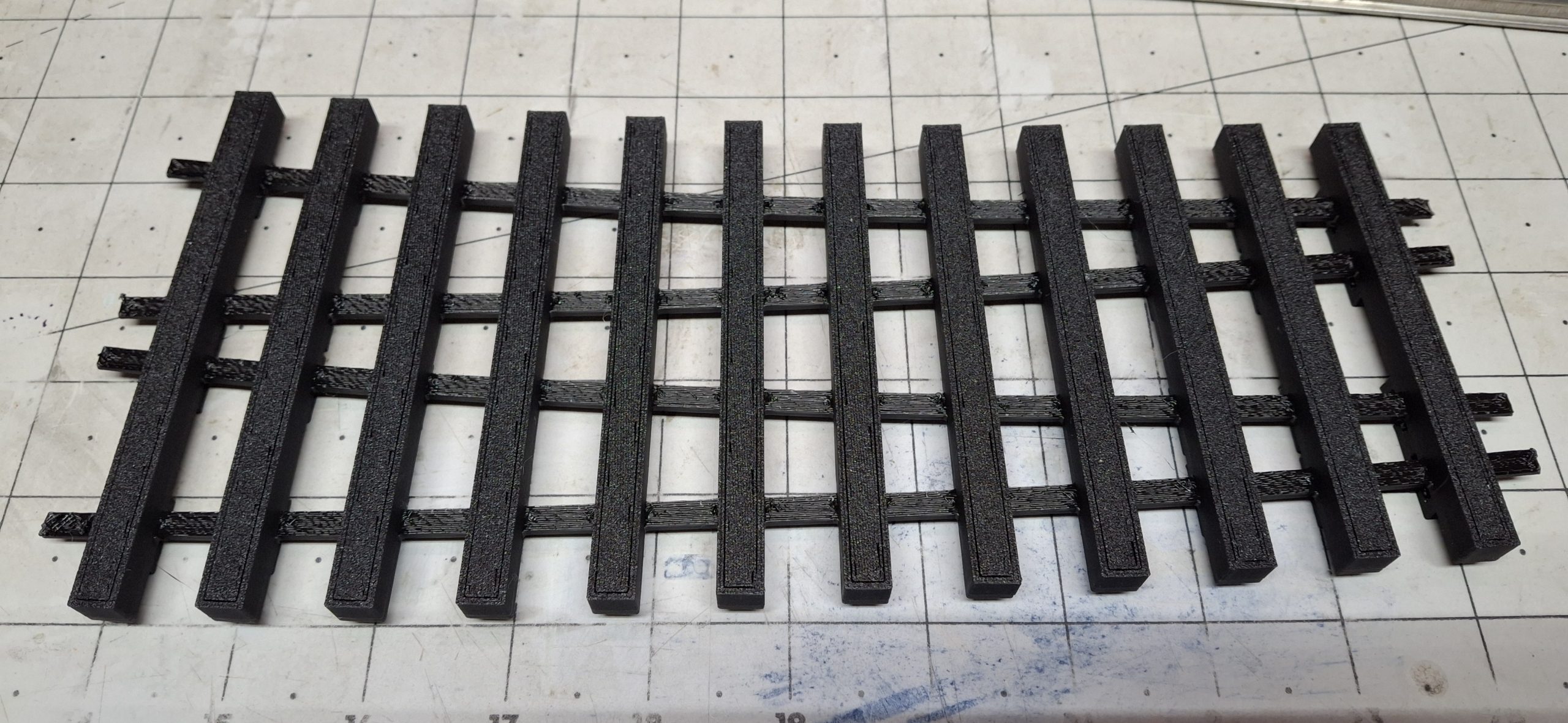
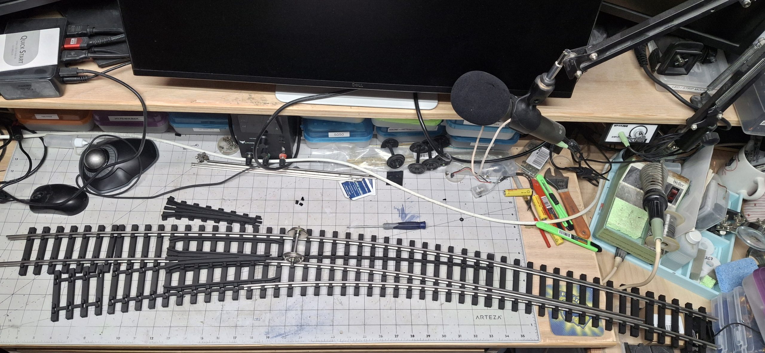
All that dedication paid off. In a little less than a week the preliminary design is complete and the prototype tie strips have all been 3D printed! Test fitting the tie strips for the heel and point rail ties suggests the fit is “a bit snug”. And by a bit snug, I mean I had to use the tack hammer to “tap” the inside 14′ diameter stock rail into position.
The remaining tie strips are printed and all the support material removed, all but those on the frog ties. Some background on the design of these tie strips. Each tie is connected to the next by a strip of material in order to keep them spaced apart and in the proper position relative to their placement along the switch. Hence the name “tie strips”. But I’m getting ahead of myself again.
Technical Difficulties
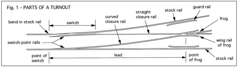
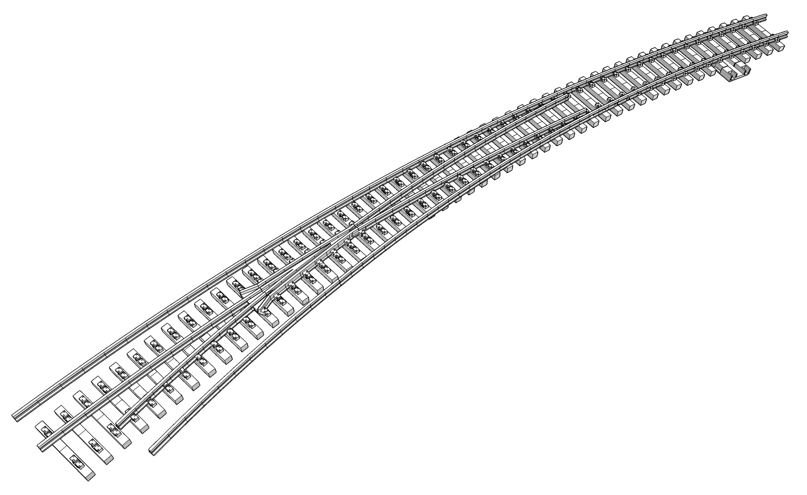
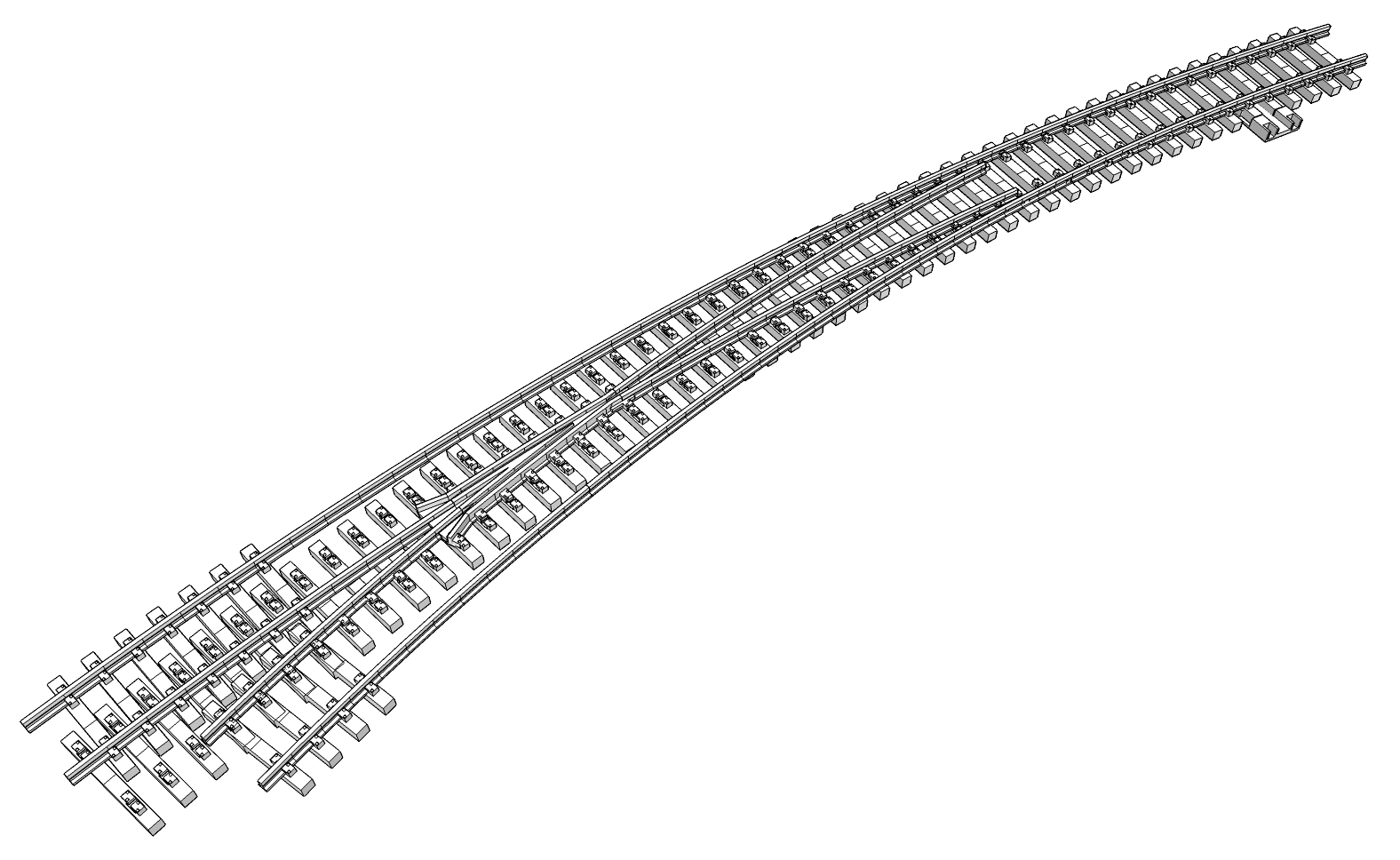
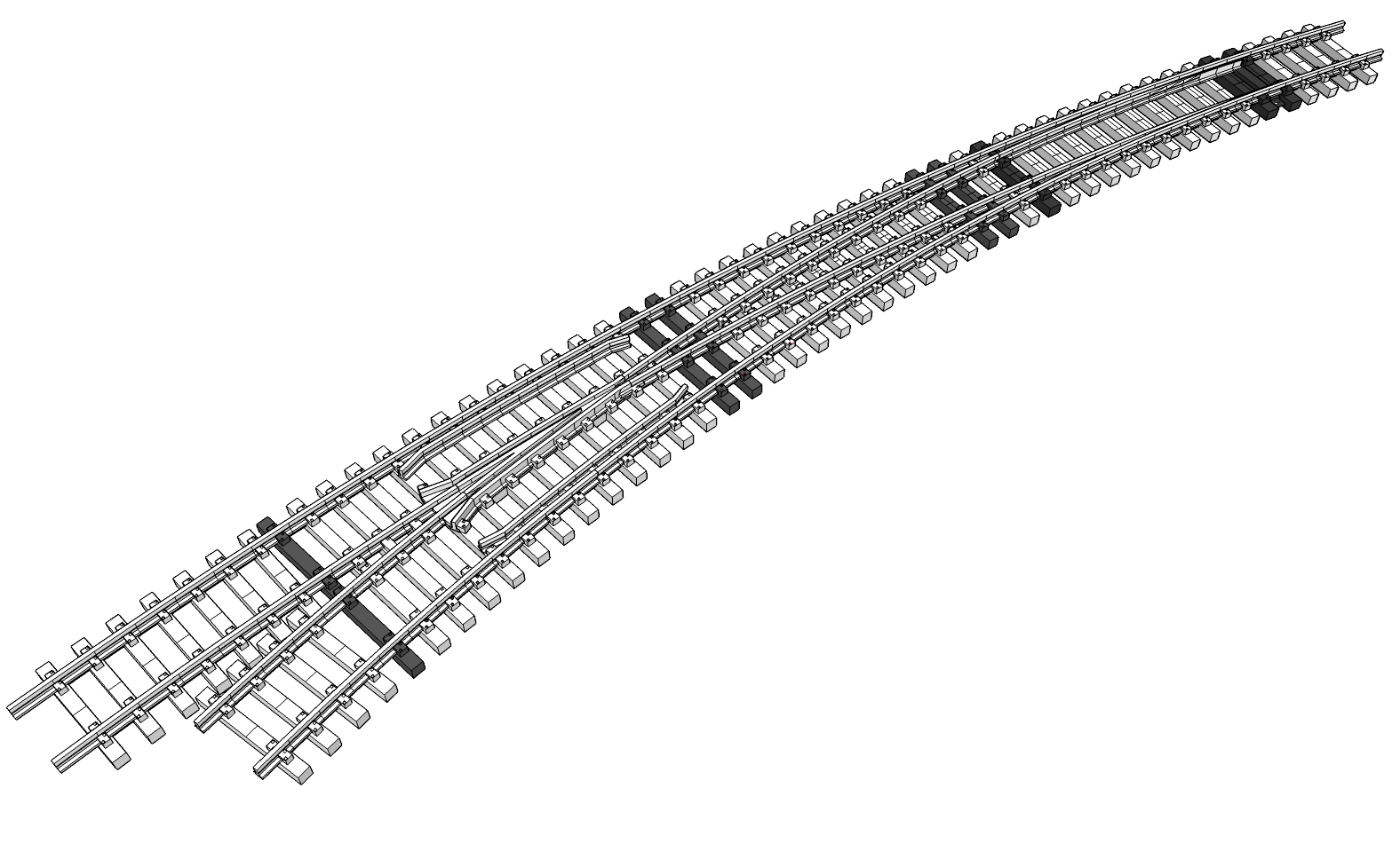
Ann tells me this is probably too technical for folks that haven’t looked at turnout (switch) design before. Too many unfamiliar terms and a bunch of hand waving around them without any kind of visual reference to help understand what I’m talking about. Let’s address that. The term “switch” refers to just a portion of the actual “turnout”, but the names are commonly used interchangeably.
Hopefully the diagram will be helpful. When discussing the stock rails, it means the two outside rails. The point rails are actually the switch part of the turnout, meaning they switch the route through the turnout, normal (usually the straight path), and reversed or diverging (usually the curved path). The closure rails are a continuation of the point rails, past the hinge point, as they’re closing in on the crossing (frog) of the diverging rails.
The frog has wing rails and guard rails help to guide the wheels through the frog. The idea is the wheel tread slowly leaves the wing rail as it also slowly begins to ride on the frog, smoothly transitioning from one to the other, starting around the point of the frog. That’s probably enough about switch design and far more than most folks would care to know about it. Again, hope this helps clear up any confusion.
Design Considerations
The tie strips are designed to be around 12″ at the longest, mainly due to 3D printer build volume constraints. The new 3D printer, an AnyCubic Kobra S1 Max, arrived not even two weeks ago and has a build volume of 350mm x 350mm x 350mm (13.77″ x 13.77″ x 13.77″). Needless to say I’ve been anxious to put it through its paces and see what it can do.
I’ve already encountered the “out of filament” event. An event that revealed what a total piece of crap the “old new” Sunlu 3D printer is when it comes to filament management. It certainly detects when it’s out of filament. It complains about it and asks for the filament to be replaced, but then loses its mind after that, requiring a power off reset to recover from it!
The AnyCubic? It functions the way the Sunlu should have. When it detects it’s out of filament, it homes the print head, remembering where it left off. Then it prompts to confirm refilling the slot in ACE cabinet. Once it detects the new filament is inserted it primes the system and awaits the request to resume printing, which it does, right where it left off! It’s a dream come true.
A Poor Assumption
It’s not all rainbows and unicorns though. As I mentioned, the fit is a bit snug. The ties are fragile, cracking and splitting along the layer lines when pressing them onto the rails. But by far the biggest drawback of the initial design is all the support material. It takes about half an hour to remove all the support material from each tie strip, using needle nose pliers no less!
Let me step back and describe the original design approach before we go much further. The design is “copied” from the original Aristo-craft switch ties. The thought is it worked for them for years, so it should provides clues where to start, and should be a good jumping off point for our design. Well, that was a poor assumption, at least for the ties themselves.
There are other limitations to the Aristo-craft switch design, but we’ll get to those shortly. Their tie design was meant to address injection molding and manufacturing constraints that we don’t have. We do have constraints, just not the same as those. Our constraints are related to 3D printing and the materials available that can survive the heat.
Differing Design Constraints
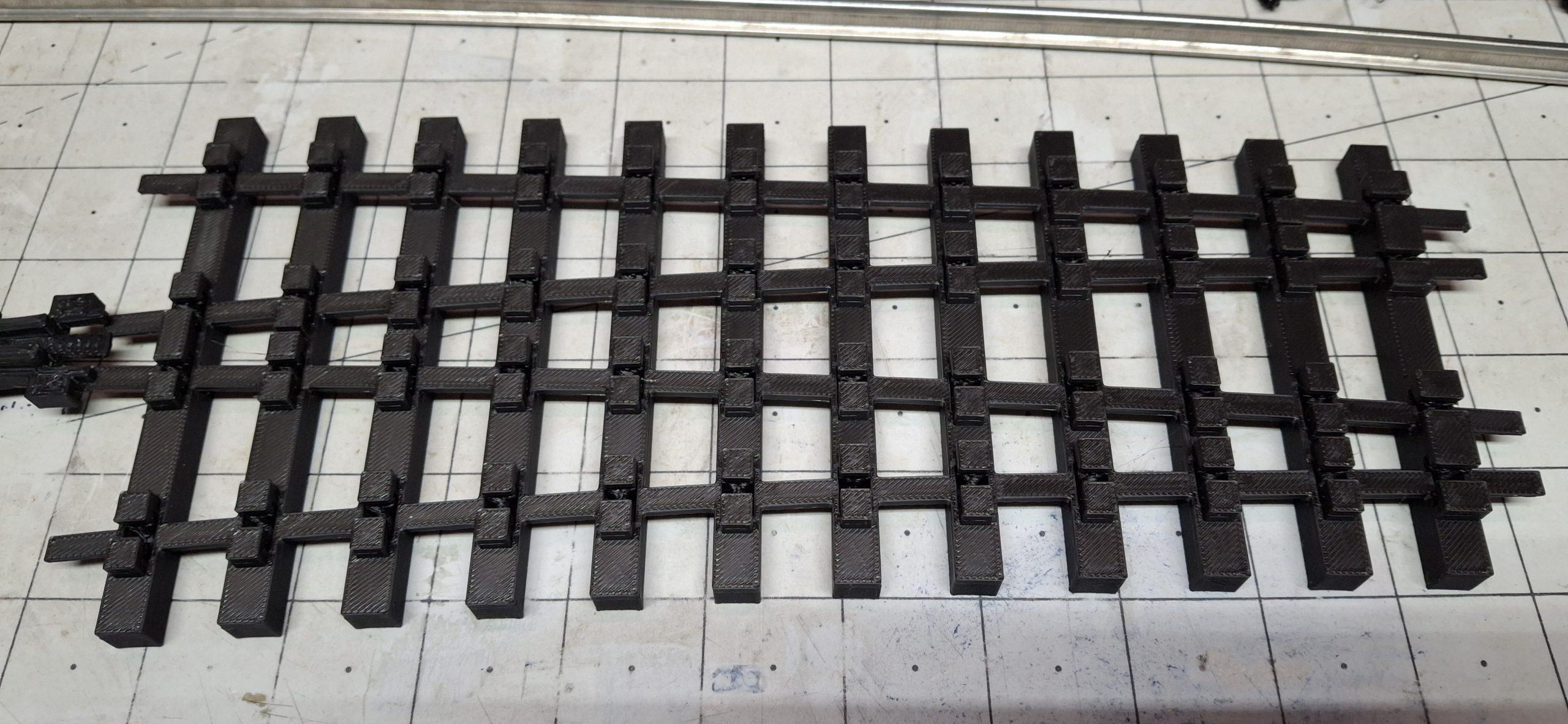
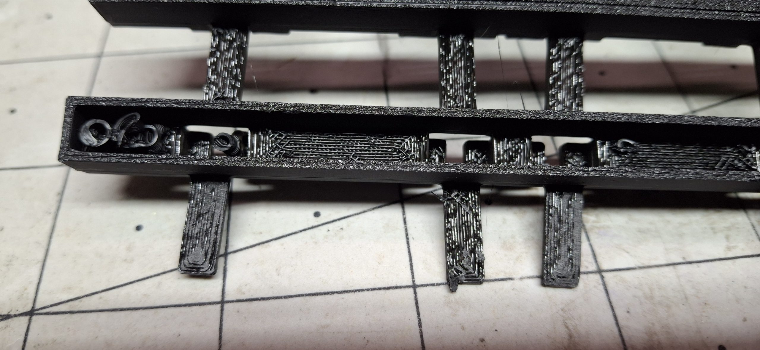
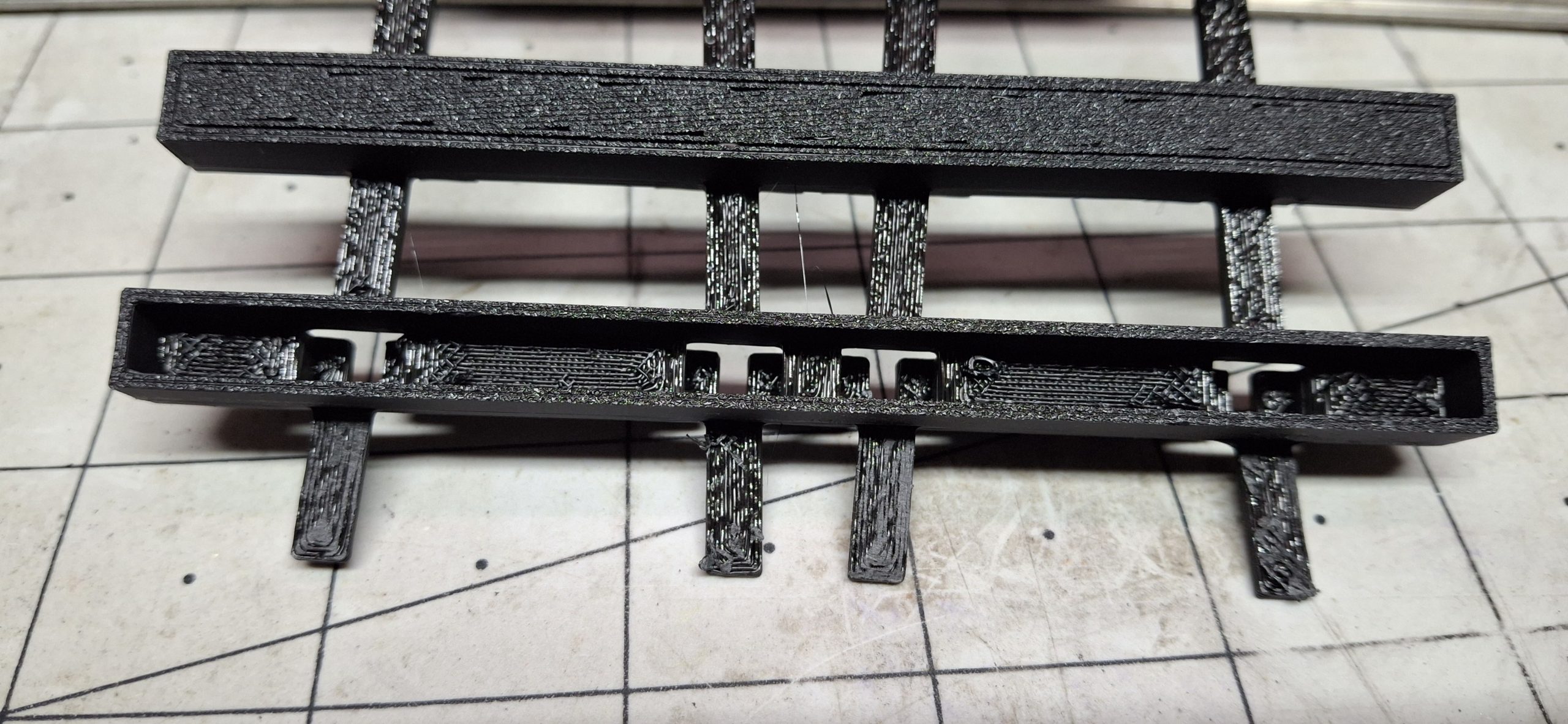
The Aristo-craft design uses “hollow” ties with thin walls and openings on the tops of the ties where the rail “foot clamps” live, presumably to conserve the amount of material injected per part into the molds and facilitate the release of the parts from the molds. Parts in this case refers to the tie strips, not just single ties.
The Aristo-craft injection molds themselves provide the “overhang” support for the underside of the top of the tie. We don’t have that luxury when 3D printing. Any overhang of more than a 50° angle from vertical will cause issues. With nothing to support the molten plastic, it droops and deforms. Those familiar with 3D printing will know it as “bridging”.
Successive layers above the area of bridging depend on those previous layers for support, now missing and drooping because of lack of support beneath them. Again, those familiar with 3D printing know that supports are “waste” material. They get printed along with the desired part, but are only there to bridge the overhangs and support the layers above.
Refining The Design
After printing is complete, the supports must be removed, usually tossed in the trash. Wasteful, but necessary when the desire is to print as one piece, not many that need joined together in some fashion. For tie strips, we could certainly print a dozen or more separate ties, then print two strips of rail foot holds, one for each rail, and glue them all together.
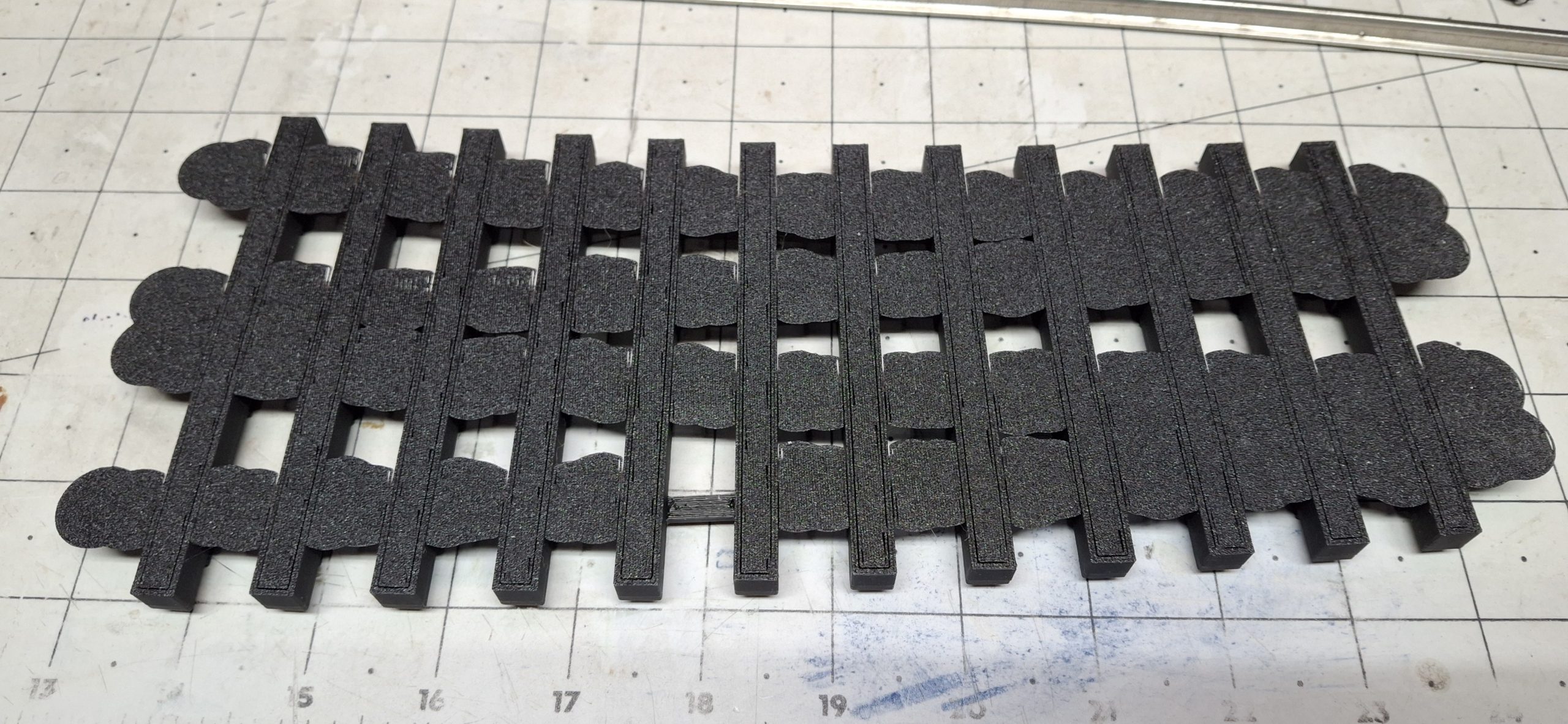
I’ve not tried that approach, but have to think it would take just as long to glue a tie strip together as it does to remove all that wasted support material inside the hollow ties. A better approach would be to just redesign the ties to be “solid”, that is to say a defined number of walls in thickness with a certain percentage of infill inside them.
The ties don’t need to be hollow to begin with. That was an injection molding constraint. For not much more material than would have gone into printing the supports then thrown away, what used to be waste material is now incorporated into the tie itself, producing a much stronger tie in the process. If it’s going to get used anyway, may as well add it to the part!
Further Refinements
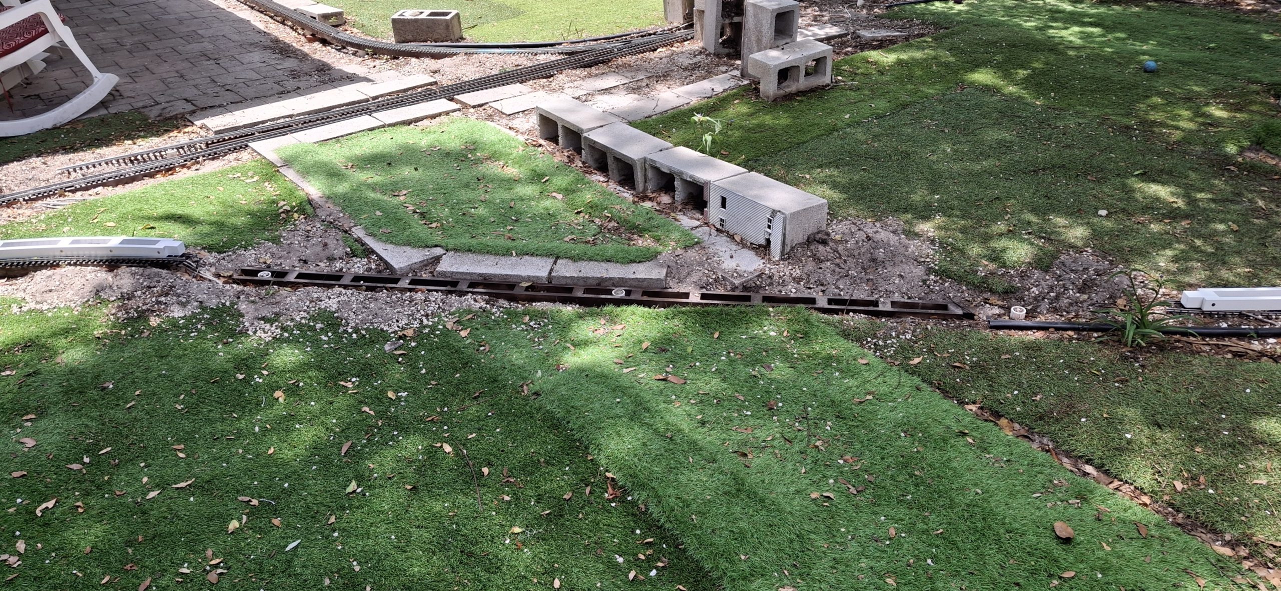
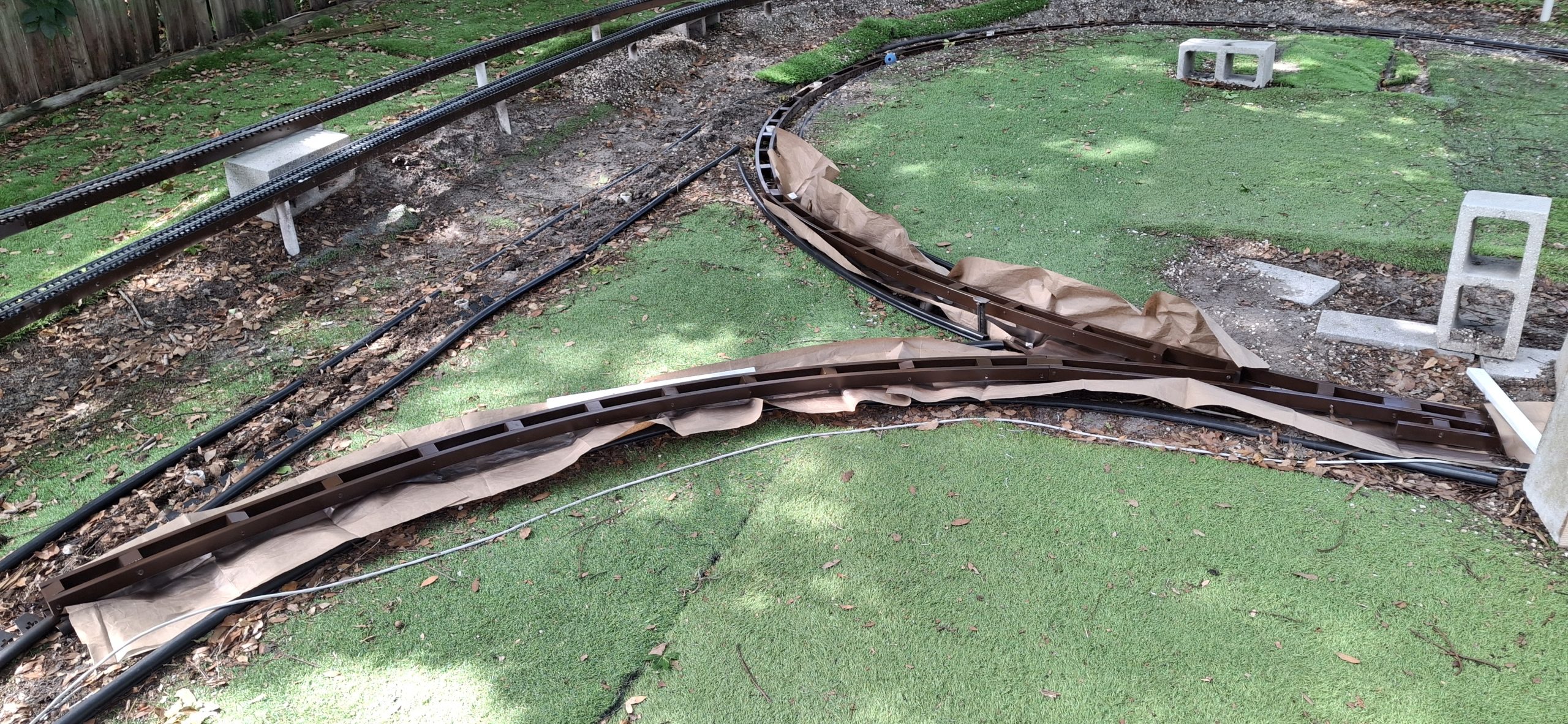
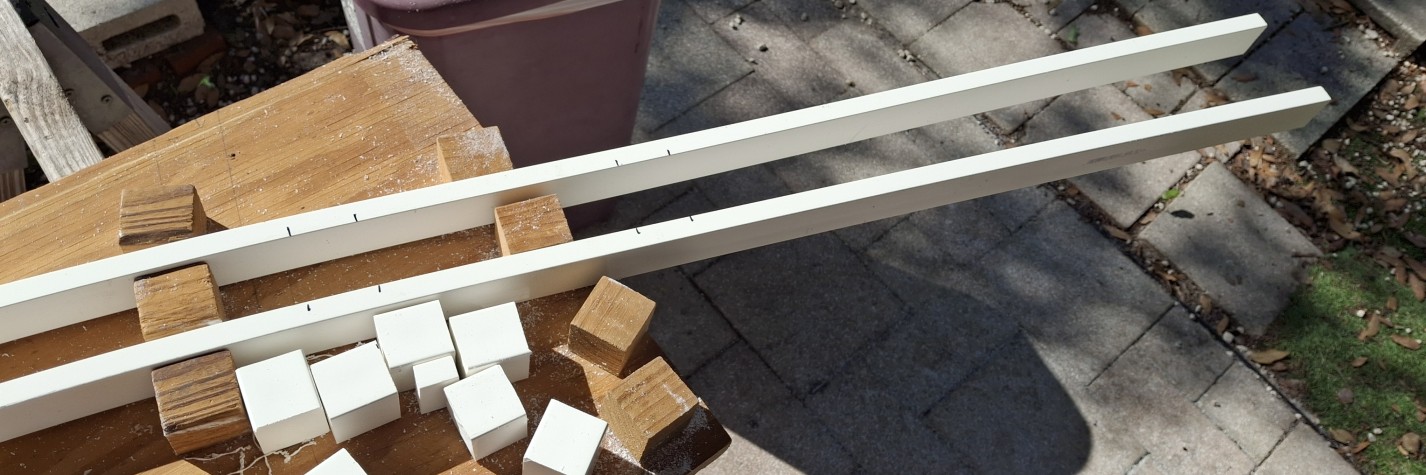
I kicked off printing the frog tie strip before getting out in the Barkyard, working on more stringer replacements. It’s more than a five hour print, which gives me plenty of time to refine the design for solid ties and put together a couple more PVC stringers. The tie strips for the diverging routes all use a single tie model, so updating the design fixes those eleven ties all at once. The rest of them? Not so much…
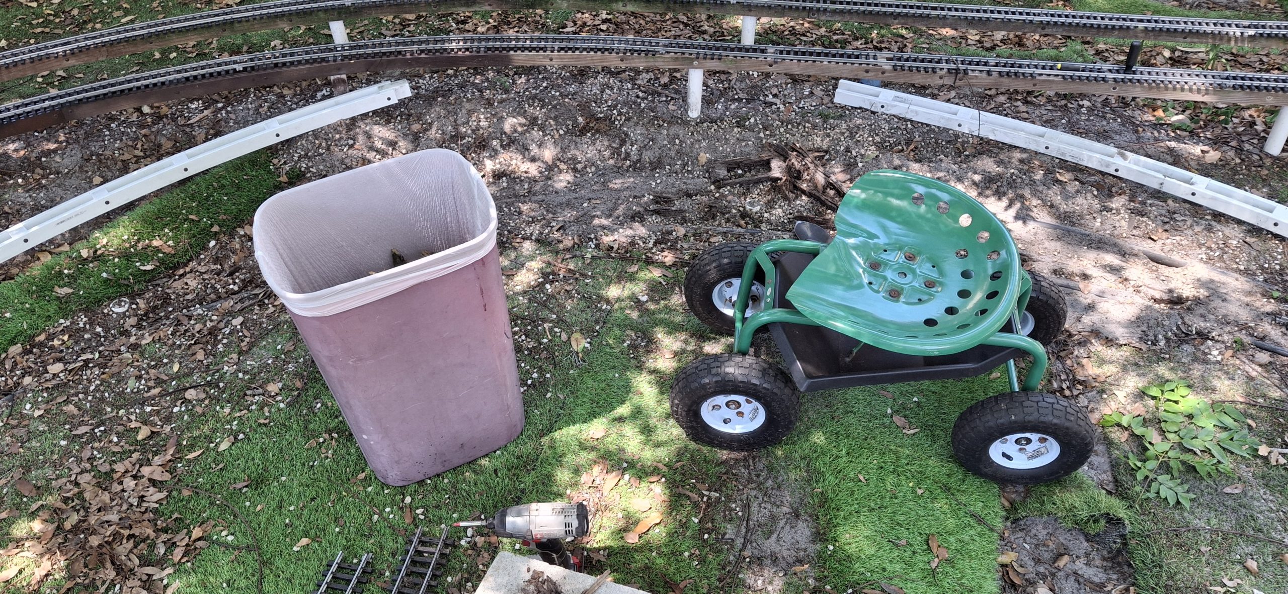
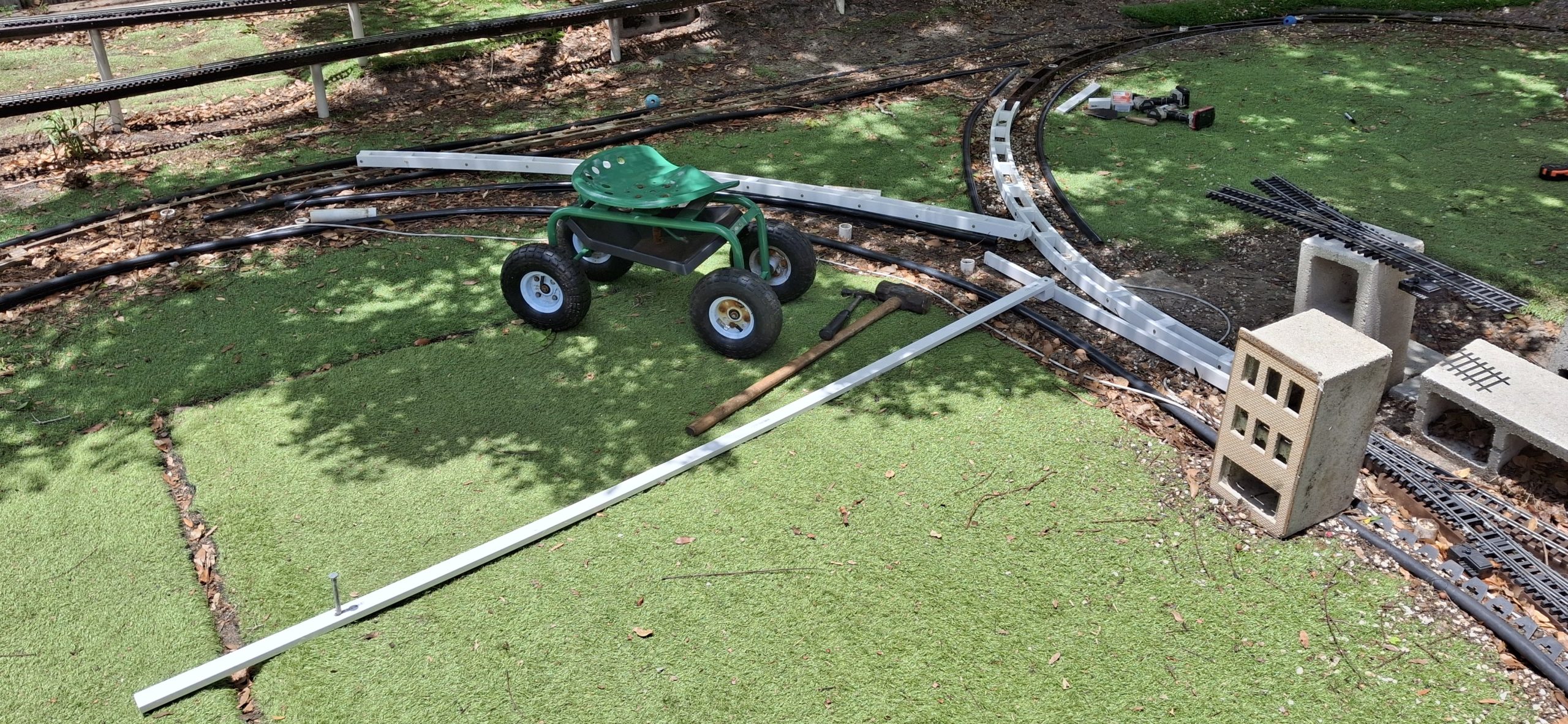
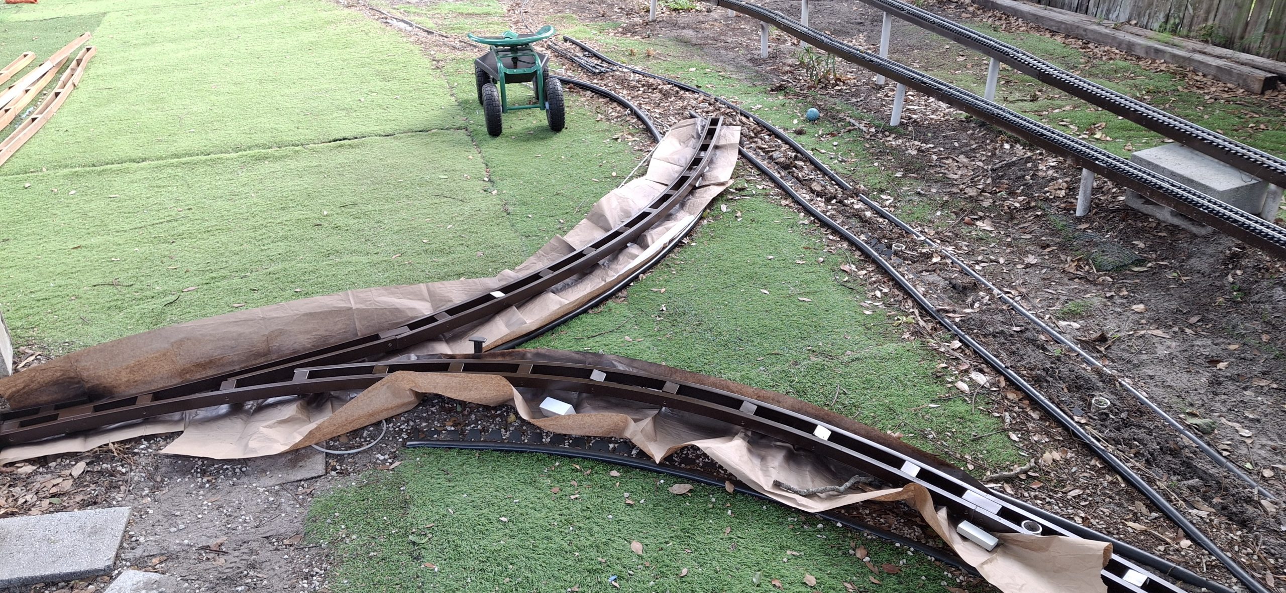
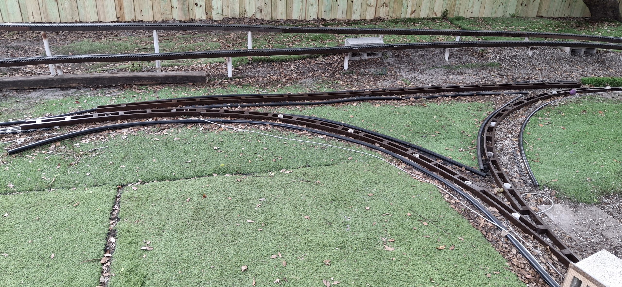
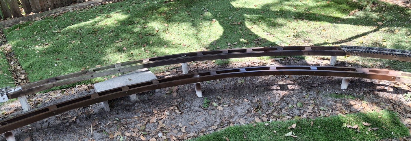
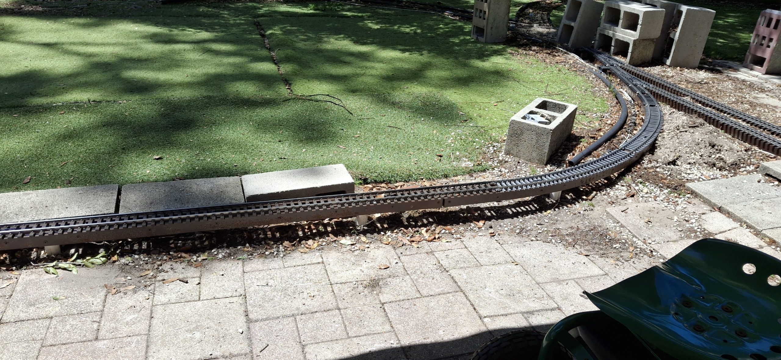
The print of the frog tie strip had long since finished by the time I knocked off for the day from replacing stringers in the Barkyard. I hadn’t planned on being out there all day, but managed to correctly re-construct the two wye legs that had been plagued by my previous misguided assumption about the wye switch. With the needed curved switch about to become a reality, it made sense to correct the mistakes of the past.
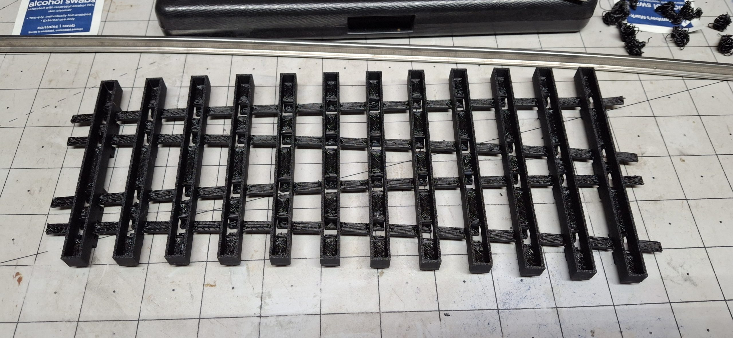
I removed frog tie strip from the build plate flex sheet and kicked off printing those diverging route tie strips. When they were done printing, I started the process of removing all the supports. This time it’s limited to just the connecting strips, which easily break off by hand, and the rail foot clamps. Those still require the needle nose pliers, popping them out from the top into the hollow area beneath. Quick and easy!
I tried removing the supports from the frog tie strip, this time concentrating on removal of just the supports for the foot clamps. The rest of the support material in the hollow of the tie can just stay there. It’s not visible, so why bother? I stopped short of removing them all though.
Further Refinement Considerations
Those diverging route tie strips are much stronger with infill and the ease of removing the supports is another vote in favor of this redesign. Another consideration for refinement is the tight fit of the foot clamps on the rails. I had already eased the fit by ten to twenty thousandths of an inch (¼mm – ½mm) in places where the rail angle compared to tie is large.
I forgot to add the supports for the foot clamps for the redesigned print and accidentally discovered they’re unnecessary! It’s a Bob Ross “Happy Accident” moment. So now we’re down to just the strap supports, which are easily removed in a minute or two. That’s a helluvan improvement over the half an hour for the previous designs.
Let’s rewind to the original design idea for this curved switch to better understand that last statement about rail angles and foot clamp clearances. Even with standard tangent to diverging curve switch designs, on the diverging route the rails fall at an angle to the ties. Eventually toward the end of the diverging routes, the ties resume their normal perpendicular orientation to the rails when they no longer interfere with each other.
Now consider this is a curved switch and regardless of which route is taken, we’ll call them them normal and diverging, since tangent doesn’t really seem to fit, both the normal and diverging rails will always be at an angle to the ties, save for those final diverging route ties. Given both routes are curved, one way to minimize that angle is to arrange the ties to the average curvature.
Initial Design Constraints
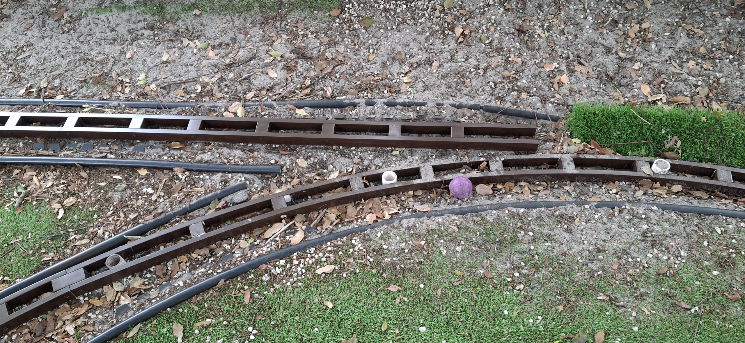
In our case, midway between the 14′ and 20′ diameters is 17′. Starting with the original tie design from way back, they are arranged every half degree for the full 22.5° curvature of an entire 20′ section. I made this a constraint to avoid the tragic outcome from my previous mistaken assumption that the Aristo-craft wye switch was a full 20′ diameter section. Ours is an entire 20′ diameter section long, coming in at around 4′.
When a full 22.5° 14′ diameter section is placed over the 20′ section, it’s only long enough to meet where the frog will sit! Anything less than a full 22.5° section of 20′ diameter track would be less than a complete switch. I arbitrarily added an additional 7.5° to the 14′ diameter route to ensure the ties from sectional track segments won’t interfere with each other.
What can I say? A hold over from my HO days where the #4 switches need a 1/3 18″ radius section for the switch to replace a single 18″ radius 30° curve section. Those legs of the wye already use flexible track segments bent to fit properly. Worst case is an extra 7.5° needs removed to fit with the new curved switch in place.
Additional Design Refinement
Getting back to the design decision to use a 17′ diameter tie layout, each tie needs to be adjusted because of this decision, more so than if it were a tangent / diverging route switch. Both routes need to be adjusted, not just the diverging route. By adjusted, I mean the length of the tie and the position of the foot clamps based on rail position as well as interference fitment.
That’s where the 10 to 20 thousandths figure comes from. Each of those 48 ties needs careful consideration, from centering the foot clamps over the rail foot, to sighting down the length of the rail from the inside to verify clearances from the tip of the foot clamp to the web of the rail. It’s like using X-ray vision to eliminate any interference between them.
One other outcome of running out of filament is the brittle nature of the replacement filament. Don’t even look at those foot clamps wrong or they snap right off!. Finding out why this filament was so inexpensive. Definitely not a bargain. Never buying that stuff again. I’m guessing what I’d been printing with before was PLA+ and this latest stuff is just plain PLA. Dunno. It’s just plain crap for sure.
Real World Considerations
The brittle nature of the filament coupled with a lack of complete support removal is a sure way to snap it right off when attempting to test fit rail. So one more refinement will be to back off the foot clamps another 10 thousandths as well as raise them all by 10 thousandths. It’s also a vote to just reprint those other ties strips using the design refinements.
But that’s not as easy as changing one model to fix all of them like it was with the diverging route ties. Every one of those remaining switch ties is unique. Most have two additional rail foot clamps beyond the original two the model they’re based on came with. The exceptions are the approach ties to the point rails and the ties under the point rails. just sixteen of them out of the 48 switch ties.
I’m going to cut this one short for now. If I somehow manage to make substantial progress tonight, then I’ll come back and update this post. Otherwise, stayed tuned for Part II. There’s plenty more to be done to make this an operational switch, but so far there aren’t any show stoppers that would interfere with that goal.
Question? Concerns? Leave A Comment!
If you’re interested in obtaining the STL files to print your own curved switch, leave us a comment and we’ll be happy to email them to you. Also, if you have any other questions or concerns, please feel free to comment on this post. In any case, you’ll need to create a user account to do so. We don’t use any personal information for marketing or to spam you (see our privacy policy). You’ll receive a verification email. Reply to the link provided to verify your email address. It’s all automatic. No waiting on moderator approval! No spamming your inbox with useless advertisements and “Special Offers”. None of that nonsense.
More to come. Stay tuned for Part II!