It’s Dead! 3D Printer Relapse

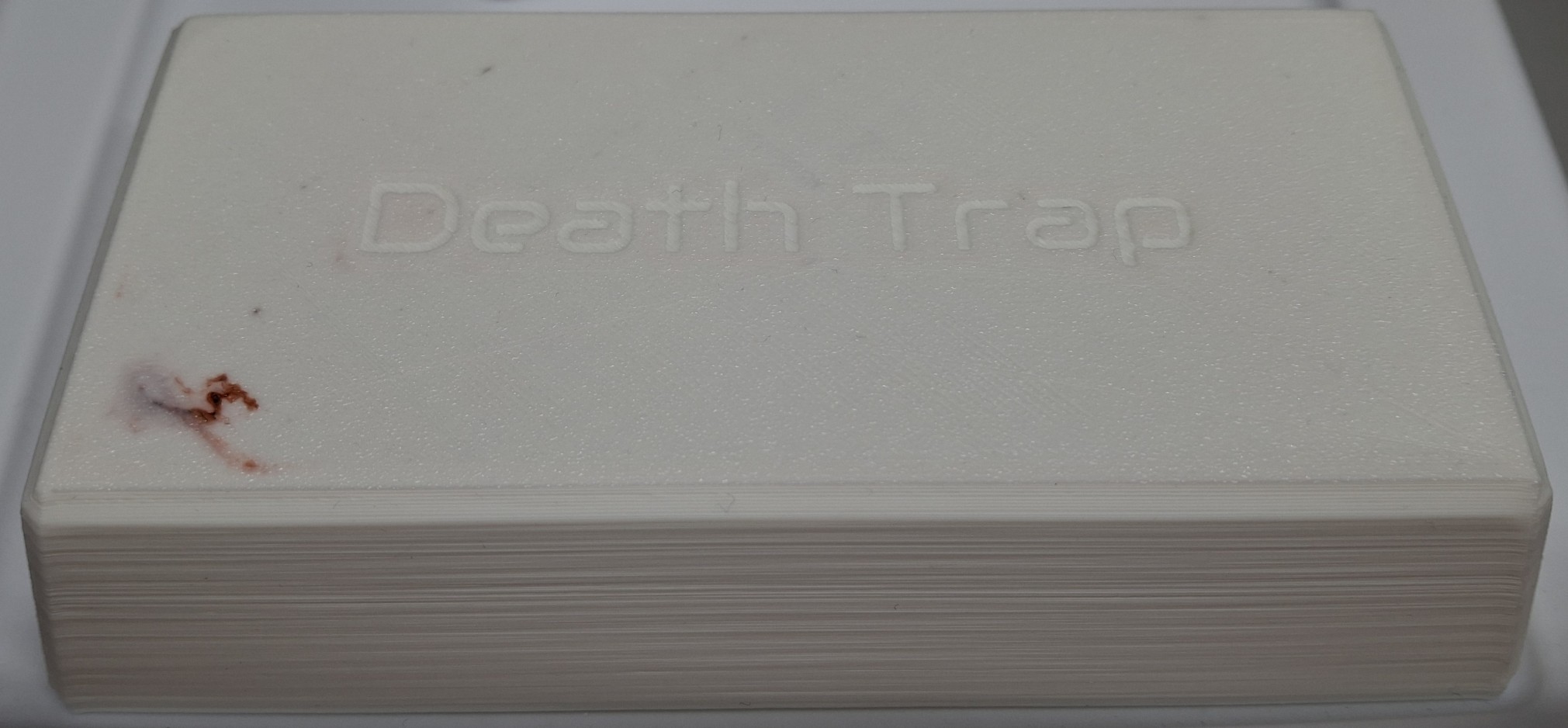
Not again! I was so happy to finally get this thing back up and running only a few months ago and it just failed on me again! Catastrophically this time, taking half my thumbnail with it! The extruder release lever broke, snapped right off, just trying to remove the filament. That sent my thumb on a rapid collision course with the printer frame. Ouch!

Blood everywhere and playing beat the clock to get the filament out before the hot end cools off, now I’m prying what’s left of the lever with a screwdriver to release it and still having to tug the filament harder than I should. I noticed it’s been getter harder and harder to remove the filament over the last week or so and should have known something was wrong.

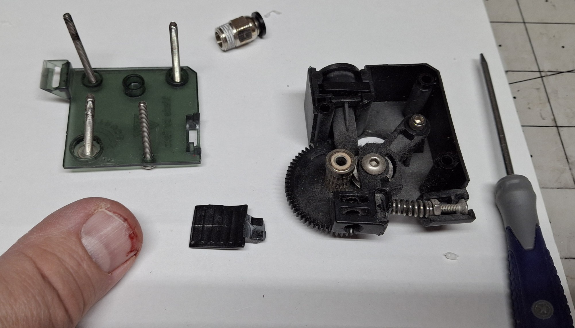
Had I known it was going to fail I could have ordered a new extruder pre-emptively. Had I known it was going to fail, I could have saved myself some pain too. I guess in some ways I already knew it would fail, eventually, being made of plastic where metal is called for. Plastic gears. Plastic case. Plastic tensioner arm. All plastic!

The only things not plastic are the gear and idler pulley that together push the filament through the extruder. That and the screws that hold everything together. There’s the spring that holds pressure against that release arm the idler mounted on, pinching the filament against the drive gear too. It snapped off right where the spring pushes against it.

The Damage To The Extruder And My Thumbnail

Time To Rewind

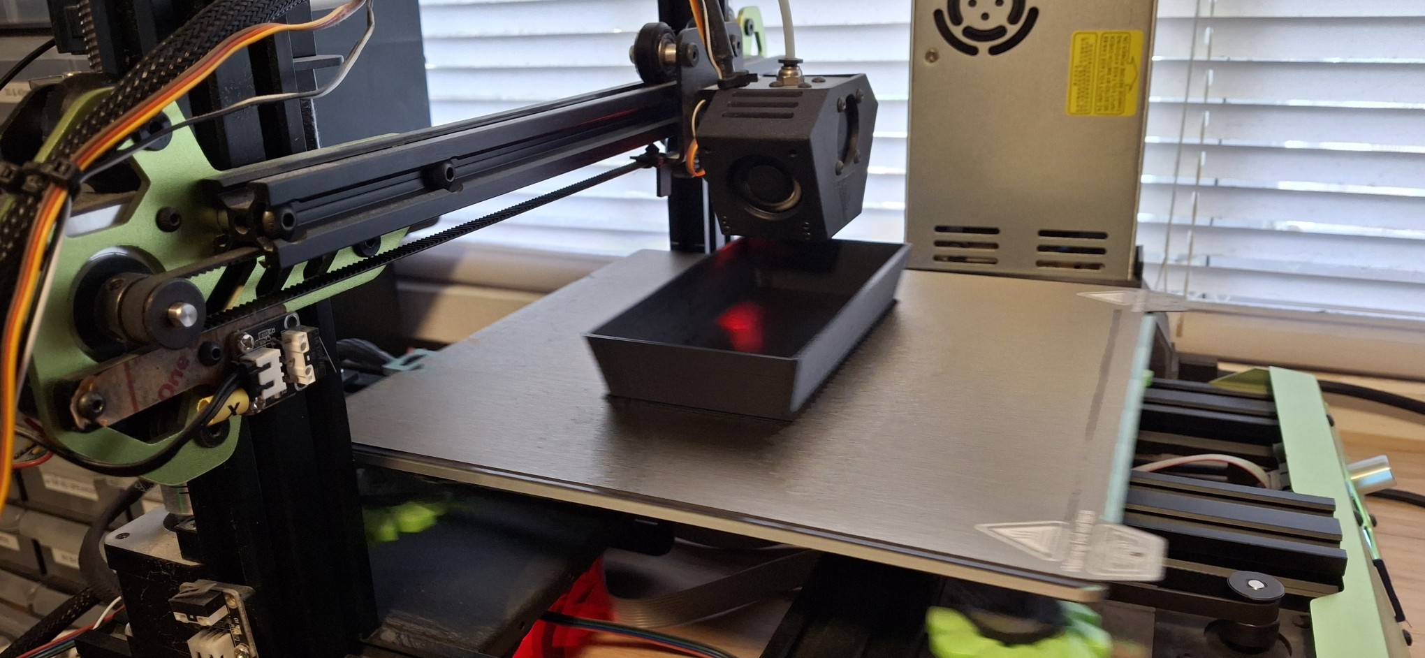
Let’s rewind a bit. In my previous post, I covered the history of this Tevo Tarantula Pro (TTP) 3D printer and what it took to get it operational and back online. I’ve been using it almost daily ever since then. In fact, I’ve been using both 3D printers nearly every day. There’s a certain satisfaction from having both of them cranking out prints at the same time.

When one or both isn’t printing something, it’s almost like OCD with me, asking myself what can it be printing now? Every post since the one about getting it working again has included prints from both 3D printers. It’s uncanny how quickly that old TTP can print. I thought I couldn’t push it any faster, but I did mistakenly and it kept right up!

The new Sunlu S9+ was advertised as capable of 250mm/sec, but even when I ask it to do half that, the TTP is still faster, even though the print’s been sliced for it using slower speeds. How is that possible? Nick has a theory on that, thinking it’s built in acceleration profiles limiting the overall speed in the new one.

Turns out I was actually sending some pretty tame acceleration limits with the startup G-code. I modified the startup G-code to remove them and modified the printer settings directly with much more aggressive values, but it still seems to obey some magical built in values I haven’t been able to find. Oh well, at least it’s almost as fast as the TTP.

Too Fast For Even My New Phone Camera To Catch

Cranking ‘Em Out

As I said, we’ve been cranking out the prints. Between Death Trap, Death Trap Jr., and the Closet Lighting controller prints, both have been kept busy most of the time since bringing the TTP back online. I used the time between prints to make minor design modifications for each new iteration of each print then kicked off the next revision.

Of course, when it takes 8 – 12 hours to print each piece of a Death Trap it gives me plenty of time to work on other designs, and not just 3D print designs. I’ve also been working on a major refactor of how the menus and meters are handled in my Arduino sketches and libraries. The motivation is to test a new round display as a digital version of an analog meter.

But I’ll save those details for later. When I say later, I mean in a later post, once it’s all working again. To be honest, I was getting overwhelmed by the immensity of the project and had to step back from it for a bit. Not going to list all the priority items I’ve already discussed in recent posts. Let’s just say the Ultimatum of end of August is quickly approaching.

The Saturn V
The Saturn V

My Saturn V Tribute

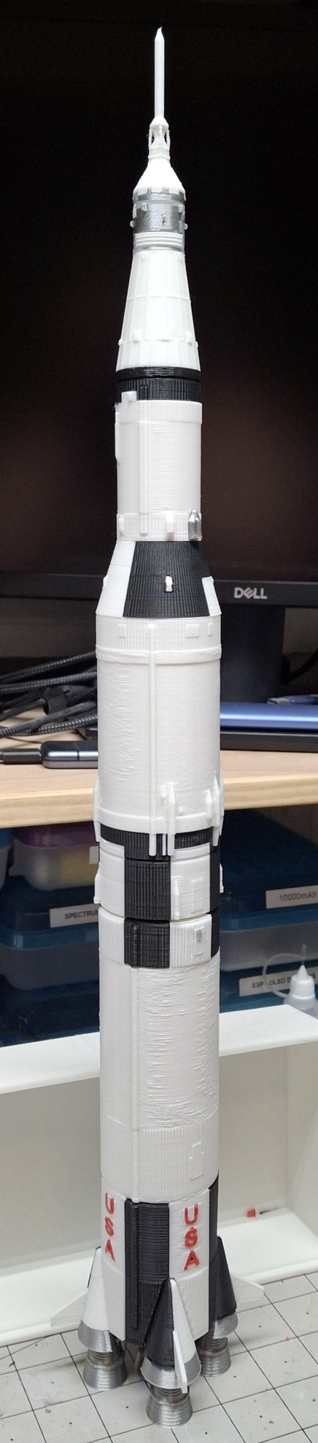
Between the Ultimatum and the constant media circus lately, even preempting the recent 56th anniversary of men first walking on the moon, July 20, 1969, I decided to print my own Saturn V as a tribute. I needed a breather. An escape from all this necessity and media insanity and it seemed like the perfect project.

Most of the parts are either black or white, with some parts in metallic silver, and a little red thrown in for the letters. The new printer is already loaded with white and the TTP with black, so I sliced the parts based on what printer had what color. Once all the black parts were printed, I loaded up a half spool of metallic silver, a.k.a. silk silver.

These were the engines, heat shields, the service module and few other interstage parts. The engines had the most supports I’ve ever printed by far. Probably more material in the supports than in the rocket engines themselves. Those supports had to come off in layers, peeling them off until getting down to the final course that snapped right off.

I should note these STL files are from a third party source and it took some doing to get them sliced for my printers. I generally design parts without the need for support unless absolutely necessary. I probably would have made the engine nozzles separate from the combustion chamber and turbo pumps and stuff so they can be printed flat on the build plate.

Finishing Touches

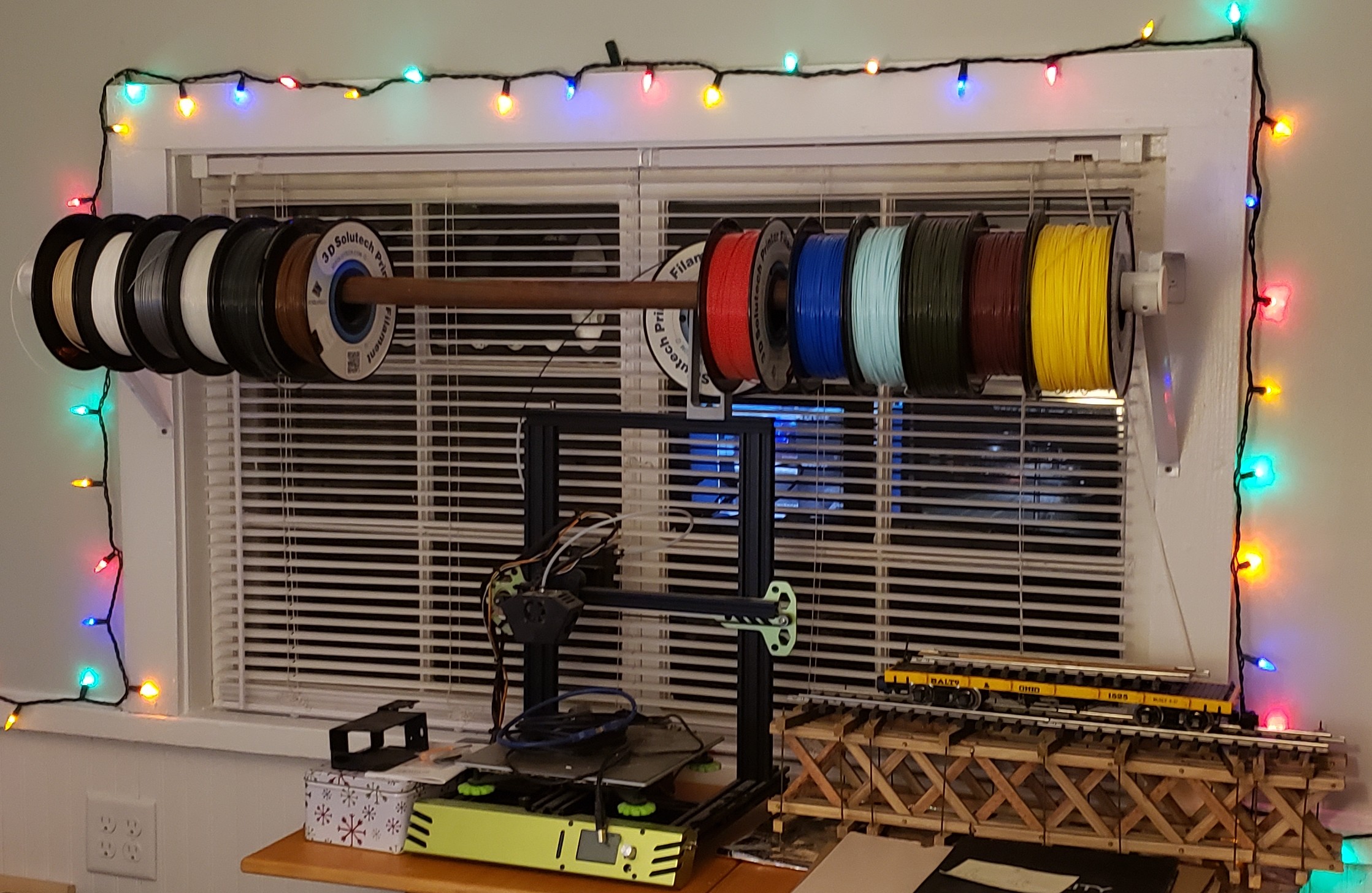
Anyway, I loaded up an old spool of what was left of 3D Solutech red. It was still coated in dust from sitting out in the office on the old closet rod arrangement I had sitting over the printers. The idea was to make it easy to load a different color by just sliding the desired color spool into place and loading it.

That was before I knew about the effects of moisture on the filament and filament driers. I loaded it in the filament drier and let it drive out as much moisture as it could first, before loading it in the TTP. Long story short, I thought I did a pretty good job getting rid of the dust. Not so much.

And it wasn’t apparent it was an issue until the symptoms of a clog started to manifest themselves later. The red letters were the least of my worries. Or so I thought at the time. Once they were done printing, I decided to print the base in red too. Think I putting the finishing touches on the Saturn V I literally put the finishing touches on the printer too.

Nice Red Pimple In A Sea Of White

Symptoms Adding Up

I originally printed the Death Trap Jr. in black, but it looks like exposure to the sun is enough to warp the plastic. I decided to print a white one with the filament left on the spool, starting with the lid. My first indication there was trouble brewing should have been how long it took to clear the red out of the hot end and replace it with the white.

It was pink for much longer than I’ve ever had to run the new material through to clear out the old. As it was laying down the first or second layer of the lid, all of a sudden it “burped” out a red “pimple”. That is to say a big glob of red that must have been still stuck in the hot end, now surrounded by a sea of white on the build plate.

That should have been my heads up. Between pulling out the filament getting harder and harder and now this, all the signs of a hot end clog were starting to come together. I thought there was enough filament left on the spool to print the base too, but I was wrong and had to pause the print to load the new Elegoo PLA+ filament.

Trouble Brewing

It was all I could do to pull the remaining filament out. I had ordered four spools of the Elegoo PLA+ in white, and loaded a spool as a test and a comparison to the white Sunlu PLA+ I’d been printing with. The TTP was reloaded with the new white and the print resumed. It seemed to print fine. If anything, it’s a slightly brighter white than the Sunlu.

Then the extruder started making that skipping noise, but given an assist from me in the form of a little extra push on the filament, it seemed to smooth out things for a while as the printing continued. The base finished and I thought nothing of it, preparing to pull the filament back out to store it in the drier until the next print.

That’s when it happened. Right around 9:00 PM Saturday night. I could not get the filament to pull back out. Pushing on the release lever didn’t seem to do anything. Until it snapped off, taking part of my thumbnail with it. So now we’re all caught up after the rewind. So why bother pulling the filament out at all?

After having the filament just randomly snap apart when left out and exposed to the humidity over a period of time, I decided to start removing the filament when the last print for the next few days finished. This allows the flexibility of keeping the spool in the drier or storing it in one of the sealed bags and loading a different spool, and whenever needed.

Replacement METAL Dual Gear Drive Extruder

Where Do We Go From Here?

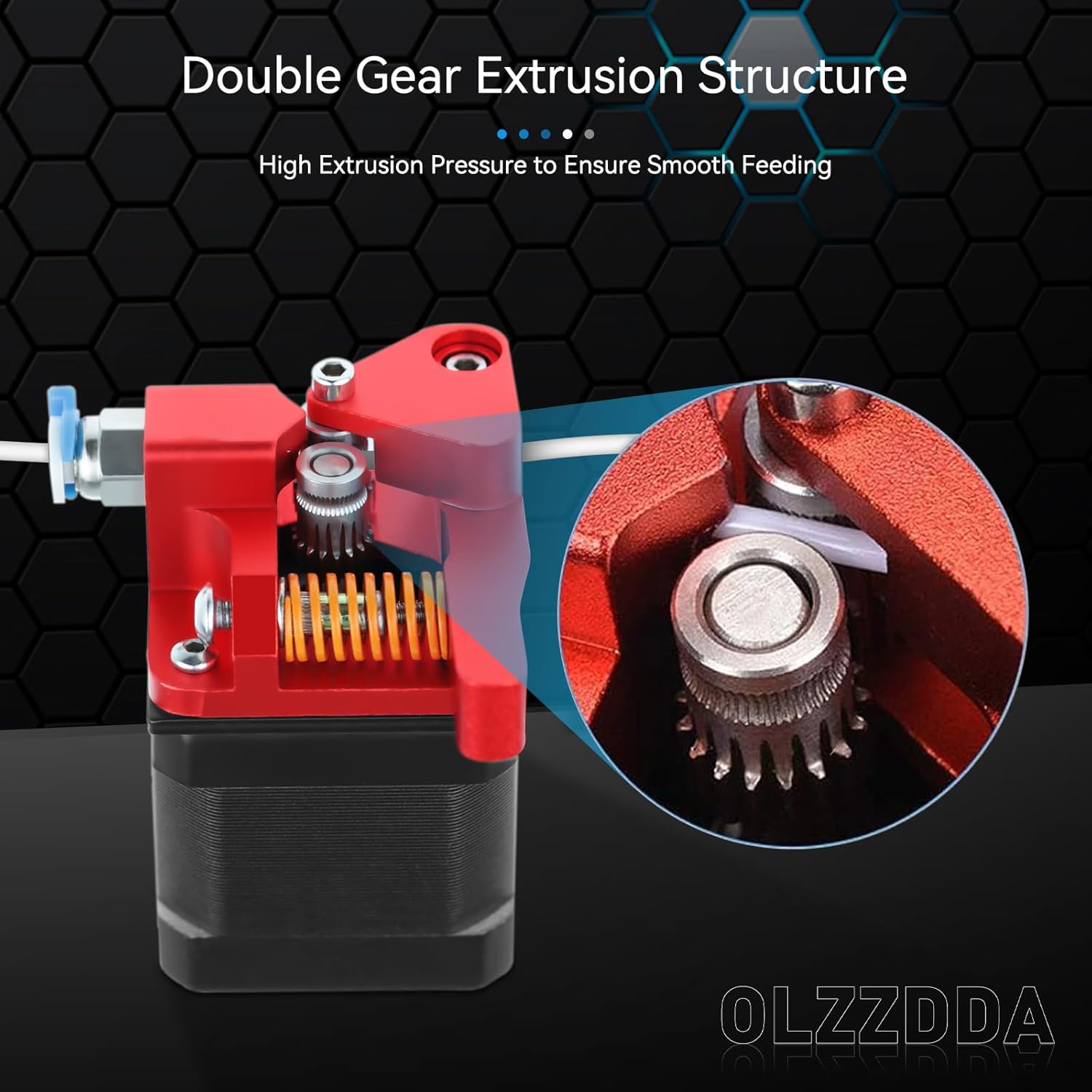
Obviously I need a new extruder. I’m not sure if I can even still source the original, let alone find one that isn’t already on its way out like my old one. Nick recommended a dual drive replacement like the one he got for his printer recently. It’s all metal, with two opposed drive gears rather than one and an idler “pulley”. The frame is all anodized aluminum.

I ordered one from Amazon and it arrived Sunday afternoon. If I have any complaint it would be the total lack of assembly instructions. I had to closely scrutinize the limited number of pictures on Amazon to piece together how things fit and where.

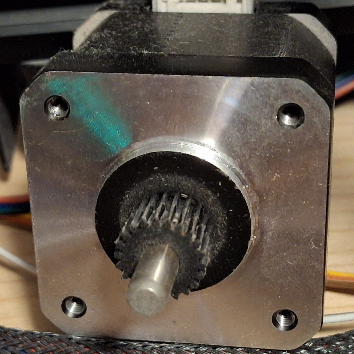
But before all that, I had to remove the plastic gear pressed on the stepper motor shaft. Thankfully there was enough clearance between it and the face of the motor to get a pair of screwdrivers behind it and pry. I only flung it on the floor in spectacular fashion once… When the screwdrivers finally lost their leverage, the adjustable wrench finished the job.

Old Pressed On Plastic Drive Gear

Fitting The New Extruder

Now it’s time to get the new extruder drive gear on the stepper motor shaft and roughly aligned with its companion on the rest of the extruder. Running the set screw down will keep it in place until final adjustment can be made. Now we can fit the new extruder to the stepper motor, separated by the mounting bracket. I only screwed up the orientation twice…

First I managed to get it 90° off, thinking the release arm worked opposite of what it actually does. The next time I somehow managed to get connector on the stepper motor facing away from the cable. Each time it had to come all back apart and the screws totally loosened and moved with it.

After a few choice words, I finally get it all put together and ready to test. Well, once I adjust the drive gear alignment on the motor shaft that is. It’s already a miniscule set screw to begin with, and it’s a good thing the hex wrench is so small and flexible, because trying to get it in the set screw would be impossible without flexing it, even with a ball end.

With that done and out of the way, it’s time to load up the filament and do some testing. And instantly I’m getting that skipping and nothing out the nozzle… So much for the new extruder fixing the problem.

Nick Lends A Hand

Nick was kind enough to take a look at it with me after supper. I had basically shut down the printer and left it off until I was ready to test with the new extruder, not giving the idea of a clog a second thought. Until now.

Nick realizes it’s taking way too much force to push the filament into the hot end. Not much if any plastic is coming out the nozzle. That would explain why the extruder is just skipping. Then he asks if I recalibrated the extrusion rate. I told him I had not. Not being able to extrude makes it difficult to measure how much gets extruded to adjust the rate.

Looking at the old extruder, it’s readily apparent that I need to make at least some adjustment since the old one had a gear reduction and the new one is direct drive, right off the stepper motor shaft. Oopsie. After “guestimating” the reduction ratio, I make a quick divide by four change, from 408 to 102. Still skipping though.

Poked the nozzle. Nothing. Took the nozzle out to see if it could be reseated without having to tear down the hot end again. I probably just made things worse by giving the molten plastic all the room it needed to fill that void, guessing that “overdrive” forced the molten plastic out between the bowden tube and the nozzle in the hot end causing a clog.

A New Hope

After having torn down the hot end twice, and finally getting it fixed only a few months ago, I NEVER want to have to do it again. But it looks like that’s what it’s going to take. That’s it for tonight. I thank Nick for his help, then shut down the printer again and leave it off until I have more time. Do I need yet another new hot end or can just clear the clog?

Tearing down the hot end takes up my entire work cell to lay the printer on its side to be able to get to everything on the printer, short of standing over it while it’s sitting on the shelf and having to turn it to reach behind it. I need that work cell for my work laptop during the day. I can’t leave the printer torn down with parts strewn everywhere. It needs to wait.

Later in the week I was chatting more about it with Nick and something he said about the opening through the hot end being as big as the bowden tube triggered a thought. Will simply pushing the bowden tube through the hot end clear the clog? A quick search of the waste basket tells me I already threw out the old tubing. Damn!

I don’t really want to dig out the new roll of tubing again just to cut a short piece. Then I remember I have an assortment of solid brass rods. Is there a 2mm rod? Bingo! If it’s not 2mm, it’s 5⁄64″, and at least 100mm or 4″ long. If anything’s pushing the clog out, this ought to work, as long as it’s not too big around.

The Culprit, A 2mm x 6mm Plug

We’ll Do It Live!

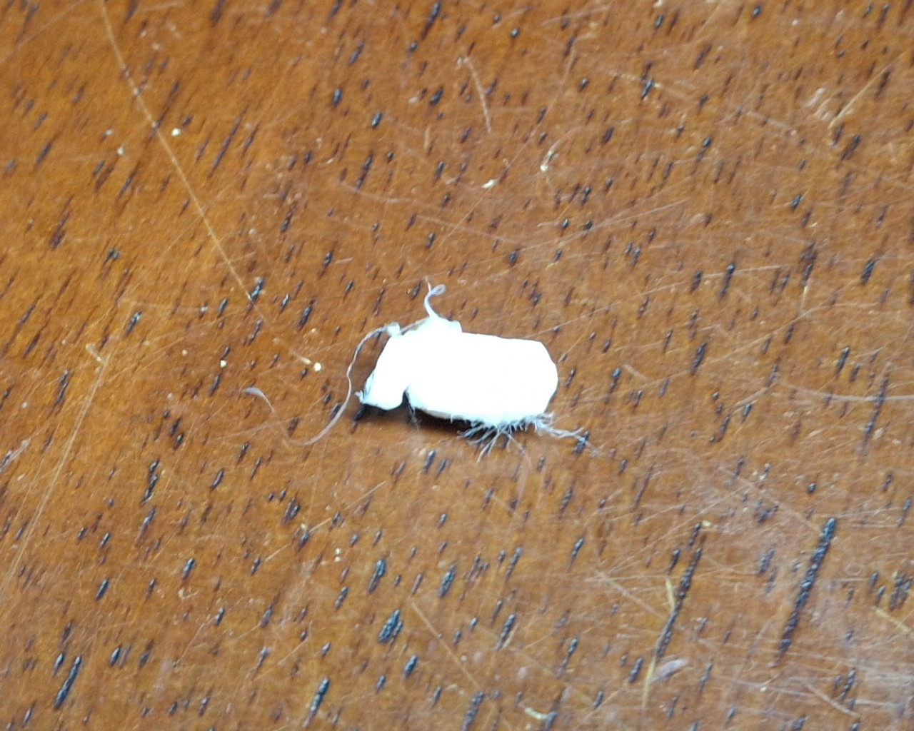
It’s a perfect fit! It quickly and easily frees a 2mm round plug ~6mm long. It pops right out onto the build plate! Nice! Not having to tear down or replace the hot end is even better! I should mention I’m doing this while the hot end is live, at temperature set for 210°C. Otherwise the plastic would be solid as a rock and stuck to the inside of the hot end.

Time to thread the nozzle back in, as fast and as far as I can by hand until it gets too hot to touch. The small adjustable wrench tightens it the rest of the way in. Next is to thread in and tighten the retainer fitting for the bowden tube coming from the extruder. Last step is to push in the bowden tube until it seats against the top of the nozzle.

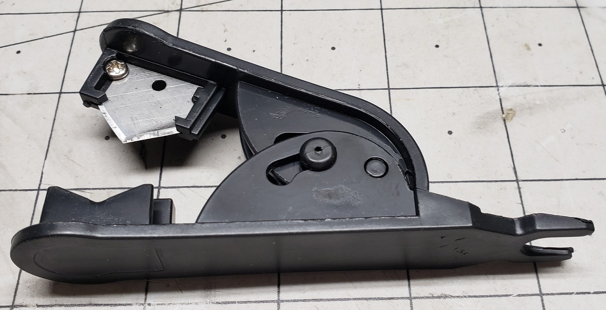
Basically the bowden tube has to fit tight against the top of the nozzle to prevent the molten plastic from oozing out around it and causing a clog in the hot end. To get that tight fit means the end must be cut absolutely straight. There’s even a special cutter tool to do just that. And you’d better believe I used mine!

With everything buttoned up, I load up the black filament, pushing it through the new extruder and all the way down the bowden tube until I feel the resistance of the nozzle. From there I command OctoPrint to extrude 50mm of filament and… Still skipping and very little plastic comes out the nozzle. Again?

Bowden Tube Cutter
Bowden Tube Cutter

We’ll Do It Again!

Let’s do this all over again then. Remove the fitting and bowden tube. Remove the sizzling hot nozzle with the wrench. Push out the clog with the brass rod. Put it all back together again. Same thing! Still skipping and very little plastic coming out the nozzle. What is going on?

Did the hot end somehow manage to clog again? How is that possible? I’m beginning to suspect the bowden tube isn’t fully seated on top the nozzle or the new nozzle is somehow clogged already or both. I try to mark where the bowden tube sits relative to the top of the fitting, but even permanent marker doesn’t stick to teflon tubing.

Let’s do this all over again. Again. This time I switched to another new nozzle, guessing not clearing the clog first just clogged the new nozzle too. This time to ensure the bowden tube was indeed fully inserted and sitting on top the nozzle I inserted it first, before screwing in the fitting and tightening it down. It definitely went in further than before!

It’s Alive! Again!

It’s alive! It’s extruding like it should! Not skipping at all! That must have been the problem, another clogged nozzle and the fitting interfering with the bowden tube and constraining it enough so I wasn’t able to insert it enough to fully seat on top the nozzle. Definitely need to remember to insert the bowden tube then install the fitting next time.

I’m so happy that it’s working again and cannot believe it wasn’t something more serious. Had I known it was going to be a simple fix I wouldn’t have waited all week to try it. But again, until Nick mentioned about the bowden tube passage through the hot end, I wouldn’t have thought to work on it while it was still sitting on the shelf.

Removing a few easy to access parts and pushing out a clog with length a brass rod is certainly easy enough to do just that though. Thankfully I didn’t wait for the weekend to try it. But before I start doing backflips to celebrate, it’s time to actually calibrate the extruder steps and run a test print.

Turns out my guess of 4:1 reduction was off, more like 2⅚, but now when I ask for 100mm of filament to be extruded I can be confident it is. I fire off a test print, crossing my fingers I won’t have to recalibrate the Z offset too. The closet lighting battery cover prints fine, although I may have heard the nozzle lightly grazing the texture of the build plate.

One More Time

I fire off another test print, this time another closet lighting switch box lid since the latching tabs were broken off the old one. Do I need another closet lighting switch box? No. Will it be nice to simply swap out one that needs charged with one that’s already fully charged and ready to go? Yes. Yes it will.

I’m not taking the time to put another one together right now though, but at least I’ll have all the parts I need to put one together when I’m ready to. With both the test prints finished and looking good, I’ll just need to keep an eye on the Z offset, looking for a telltale groove forming in the texture of the PEI sheet.

Desperately trying to find something else to print so as to keep exercising the printer but coming up short. Already have more than enough run in stands of various colors, like black, navy blue, and white.

Speaking of Navy Blue, that’s another 3D Solutech color I can’t seem to match and I’m down to the last few layers on the spool. And it was just as dusty as that red was that I’m pretty sure caused the clog in the printer.

Lessons Learned

I learned a number of things from this one. A number of things that I should avoid or do differently in the future. And I learned a method that will make it easier to remove another clog in the future if it happens again.

The first is even though I think I got all the dust cleaned off from those leftover 3D Solutech spools, they aren’t clean enough to avoid a clog. Maybe I can rinse them off then bake them in the drier to drive out the moisture. I hope it doesn’t totally ruin the filament, but at this point, it’s already ruined unless I can find a better way to clean off the dust.

The next is to insert the bowden tube into the hot end fully to ensure it’s flush against the nozzle before installing the retainer. And this time I learned something new, an easy way to clear a hot end clog without having to tear it all apart. Had I known this before destroying the original hot end the first time I had it apart, I could have avoided having to replace it.

Another thing that I learned before this happened is moisture is the enemy when it comes to 3D printer filament. I learned this the hard way when the exposed filament loaded in the printer would just randomly snap, becoming brittle from the moisture. The problem is the remaining filament is just as brittle and removing it may be difficult or impossible.

So Long Solutech

As an aside, 3D Solutech used to be my go to filament, made in many different colors. A much larger range of colors than most every other manufacturer. For example, Wheat, Skin, Denim Blue, Navy Blue, Merlot Red, etc. Their Merlot Red is a very close match to the maroon color of the AT&SF passenger cars while their Navy Blue a close match to B&O Blue.

Their products are no longer available since they went out of business years ago. Amazon’s available stock lasted for another year or two until it was finally depleted. I still have a large stock, vacuum sealed in the box, but once it’s gone, it’s gone. Like the Navy Blue, all I have left is a few layers on the spool, maybe one or two.

The only alternative is to paint the parts, in this case with B&O Blue, a.k.a. Bando Blue. But even getting matching paint has become more difficult as major manufacturers have left the market, citing low sales volume. So now everyone’s in the same boat as those who modelled a road name with colors no one carried, having to hand mix their own.

Ill Advised Attempt To Keep All Spools Available

Live And Learn

I also have a large stock of already open, dust impregnated spools that used to sit out on a wooden closet rod above the printer, exposed in the office environment, some for years on end. I’m really hoping the idea of rinsing the filament clean is a viable method to reclaim them. We shall see.

I’m faced with the prospect of just throwing them out. For those near empty spools, it’s not so difficult, but the nearly full ones I’d really like to save if at all possible. A dozen spools at $20 or more a spool is a $250 loss. I’ll learn my lesson the hard way it seems.

But it’s more than just the money. It’s the lack of suitable replacement color options. Sunlu has a large selection of colors, but nowhere near as many as Solutech offered. My favorite color to print prototypes with was “Mint”, an Aqua shade, but lighter. Kind of like powder blue but with more of a greenish tinge added.

Fringe Benefits

Oh well. At least now the filament sits in a filament drier meant to drive out the moisture. As a fringe benefit of being totally enclosed within the drier box, it also protects the filament from dust. As I said, the only issue is with the exposed filament if it isn’t removed from the printer after the last print for an extended period of time.

For now I should also learn to just take the win and move forward. After a relatively simple fix, I’m once again blessed with a working printer. Two working printers for that matter. And both are sitting idle, awaiting their next assignment, with exposed filament until then!

I hope you enjoyed this post and the “surprise” ending of a not dead again printer. Hopefully by the next post I’ll have the design for those concrete molds for the switch ladders. We shall see. Stay tuned, more to come.


Closet Lighting

I’ve made small progress on many different things today. Not as much as I wanted to get done, but I never do. The one thing I really wanted to get done was cleaning out my bedroom closet the rest of the way. There’s kind of a short story surrounding that, so I’ll try to keep it brief…

When we remodeled the back porch, there was a lot that needed done. It was a disaster. Everything was covered with cheap, thin paneling that may have been tempered Masonite™ at one point, but now brittle and crumbled in your hand. Not only did it cover the walls to the outside, but it also formed the bedroom closet walls. It had to go.

There was also a makeshift passthrough door in what was supposed to be a wall between the laundry room and the extra storage room off what became my bedroom. That extra room became data central. Not all at once, but over repeated incarnations to what it is now, each time to increase and better organize storage as well as provide better utility.

Old Craptastic Closet Wall Panelling

After tearing out all that crappy paneling, and the bedroom closets, and studs that framed them, it really became one big pass through until I rebuilt those closets. I used bead board, with the outside facing the back porch painted white, and the inside left as natural wood. I even used cedar for shelf cleats and the closet rod hangars. Absolutely beautiful!

Closet Lighting

The only thing missing is lighting. There was no provision for lighting in the original closets either. Probably a good thing too considering most of the house power came from one of those ancient, original knob-and-tube wiring feeds. One spark and all that crappy paneling would have lit up like tinder and burned the house down!

Ann got around it with a battery powered “tap” light stuck on the bead board ceiling in her closet. I could have installed light fixtures and surface type switches with that flat, snap conduit, but we had already completely rewired the house long before doing the back porch and rebuilding the closets. Battery power it is. Then it hits me…

Why not use an arrangement like the office lighting strip? I grabbed my tape measure and verified the closet is a little more than 38″ wide. Wide enough for one of the two segments in the LED office lighting. The only difference is the office lighting has a dedicated mains power supply supplying many amps, 6 or 8 amps @5 volts IIRC.

The closet lighting will need to run on rechargeable battery power with a limit of about an amp. I have a couple of leftover passenger car lighting 3D printed battery boxes, already wired up with a 2000 milliamp hour cell, ready to go. But that would only be temporary.

Dual Strip Office Lighting

Another Lighting Controller?

Yes, another lighting controller. I really need a bigger switch, housed in a removeable box that can be moved to a charging station. I’m already behind the 8 ball on getting other 3D print designs finished and really don’t want to add yet another to the list. For now, just the ability to unplug the LED light strip from the controller box will be good enough.

I have enough of the extruded aluminum channels with diffusers to make up another segment. The nice thing about using a 3′ segment like the two that make up the 6′ light in the office is I can reuse everything from the office lighting sketch with minor modifications to the configuration and web page to support just half, 55 rather than 110 LEDs.

Each pixel has it’s own red, green, and blue LED, each consuming ~20mA each, plus whatever the consumption of the single control chip per pixel is. Let’s say 60mA per pixel as a nice round figure. The bad news is all 55 pixels on at the same time at “full tilt” will consume 3.3 amps at 5 volts! Our poor little passenger lighting setup will handle maybe 1 amp.

Thankfully the lighting controller can set them to ¼ power to bring consumption back under an amp. I was hoping to put together the new lighting segment tonight, but I forgot these extrusions are a meter long (39.36″), not 36″, and need cut to length. In any case, it’s a tomorrow thing.

It’s a Tomorrow Thing

My thought was just use the table saw with the miter gauge to trim the aluminum and diffuser to length together. Easier said than done with the garage in the state of disarray it’s in, stuff stacked on the table saw and strewn about the floor and everywhere. Hacksaw it is. A quick file to remove the burrs and it’s time to stick on the LED strip.

Once I’ve soldered the pigtail connector to the LED strip, I prep the extrusion with an alcohol pad then remove the protective strip from the double sided sticky backing, a little at a time, while placing the LED strip against the extrusion and pressing it down in place. With that done, it’s time to add the diffuser and end caps and give it a test.

I already modified the sketch config and HTML page to match the “half” office sized LED array last night. As I feared, the battery power gives out once a certain brightness threshold is reached, resetting the Arduino. Time to regroup. After some figuring, I decide to split the 55 LED strip into two, a main light of 30 LEDs, and an under shelf unit of 25 LEDs.

Another hack job, literally, with the hacksaw. Time to solder on another pigtail to the second LED strip and add a harness to another Arduino then program it for the second light strip. Also need to reprogram the original to have fewer LEDs and a new HTML control page as well. Those edits are fairly quick and my soldering job is soon tested.

Repurposed Passenger Car Lighting Controller

It Ain’t Pretty

The original idea was to use one of the spare passenger car lighting battery boxes to power and control these things. But now that I need two of them, things are getting complicated. Add to that the tiny slide switch used to power on the unit is difficult to find, let alone know which way is on if accidently left on and the battery goes dead.

It’s not a deal breaker, but it could certainly be much more user friendly, and obvious which way is on. I used double sided tape to stick the battery box to the wall of the closet and routed the wiring harness I assembled to connect the LED strip to it. After drilling pilot holes and securing the mounting clips with screws, I snap the extrusion in place. Time to test.

It works great, but it ain’t pretty, and it suffers from all the drawbacks I already mentioned. Unfortunately, recharging it was an afterthought too. At least it became apparent it was once I realized where I stuck the box to the wall didn’t allow access to the existing charging port. Now I get to gut the thing and pull out the battery every time it needs recharged!

Add to that the placement of the LED strip at the top of the closet leaves a rather pronounced shadow beneath the shelves. That’s where the second strip comes in. It will mount beneath the shelves to illuminate anything beneath them. Once I attach the mounting clips and snap it in place that is.

Best Laid Plans

Originally I didn’t plan on a light under the shelves since all it would do is backlight the clothes hanging in front of it. Now that I’ve cleaned out the closet and donated everything that didn’t fit, I’m left with one polo shirt and my motorcycle boots. There’s no reason to leave that polo shirt hang in the closet and gather dust since I no longer need to wear it to work.

I work 100% remotely now and I’ve only needed that polo once since starting this job. So now it’s folded up in my dresser. Beyond all that, it’s not long before the gutting to recharge the battery renders the battery box inoperable. The original idea of reusing what I already have is quickly dissolving into a new design adventure.

Not what I wanted at all. In fact, it’s exactly what I wanted to avoid. Certainly nothing I have time for, but it needs done nonetheless. A couple of design decisions later and I have the the HUGE 10,000mAh batteries out along with their dedicated power bank charge controllers. After a few charge and discharge cycles, I remember why I mothballed these things.

It takes hours to get to 75%, then minutes to reach 98%, where they sit for a long time before reaching 99%, then 100%. They certainly don’t garner trust in the charging readings, being the finest quality Chinesium, but they do have a nice remaining charge display and can provide more than an amp of current.

Three Styles, Newest To Oldest From Left To Right

New Designs?

Looks like I’m designing a new battery box with the dimensions of a standard switch box to hold the HUGE battery and switches big enough to be seen. The problem is I have so many different types of dedicated charge port (DCP) controllers, it requires multiple designs.

Basically I have three styles of DCPs to worry about. The first has one of those bright white LED “flashlights” that turn on when you press and hold the button. The next an older style twin USB A output with a single USB micro charge port. The third is a newer, high current twin USB A output with USB micro, USB C, and Lightning charging ports.

I chose the second style for the prototype design. The flashlight version is an LCD with a bright blue backlight but it suffers from the LCD off axis lack of viewability issue. The other two have bright white LED displays. Much easier to read without the off axis problem. The first iteration has half the access opening in the “case” and the other half in the “lid”.

The only problem with that earlier version is that to be able to provide access to the charge port from the bottom of the case, the wakeup button is on the opposite end from the outside of the case. After trial and error and three or four iterations trying to come up with a feasible mechanism to remotely push the button, nothing is working reliably.

Double Whammy

After trying to look up the specs on the unit, it becomes apparent it’s no longer available, superseded by the newer, high current version with more charging port options. So that coupled with the button on the wrong end is the double whammy. The newer unit has the button on the opposite end so it can be accessed from the outside of the case.

Not wanting to give up on the older version, I decide to go with a “universal adapter” approach where the case and lid have cutouts in the proper location for access to the USB A and charging ports, but the specific access port locations are contained in an adapter that attaches to the lid. It doesn’t seem all that important now, but boy am I glad I did it that way!

After printing countless iterations of both adapters, I reach the final designs. The case has an access “hatch” to allow sliding in that HUGE battery with a snap in cover to keep the battery from falling out. The lid provides openings for two round LED rocker switches to snap into.

Various Iterations Of Cases And Adapters

The Final Design

The final case design simply allows a generous opening for any port configuration of the chosen DCP. Previously the case and the lid both contributed to the port access closure. The adapter is now responsible to “form fit” and fill in around them. The case also provides openings to snap in two of the standard black three pin connectors these LED strips use.

There’s a bit of a story behind that, but I’ll try to keep it short. For initial fitment, I prefer to make small test prints that print quickly and allow fast turnaround adjustments to home in on the final sizing and spacing. But if I had the actual connector specs, I could shortcut the trial and error design effort even more.

After Googling a bulkhead style connector for way too long and getting nowhere, I finally realize the connector that’s attached to the LED strip has a set of snap in retainer arms already built in! DUH! But now the issue is I need that connector on the supply side from the Arduino, not the supplied side on the LED strip, so it can snap into the case opening.

Rather than rework or remake the LED strip and cabling that’s already in place, I decide to solder up and assemble an “adapter” cable. In other words, a “gender bender”, in the parlance of the ancient serial port connectors we used back in the day. A quick test proves it works as intended.

Trouble In Paradise

That’s not the last of the soldering necessary though. The rocker switches still need wired up to turn on two separate Arduinos. Two you say? Why two? Because there’s no way to wire the rocker switches to both provide power and act as an input to indicate which LED strip to energize, short of using blocking diodes and further complicating the design.

It’s the quickest way there, and considering I didn’t want to take the time to do any design on this to begin with, it’s certainly turned this into a much bigger project now. I have Arduinos to spare, but I don’t have time to spare to update the sketch to control two LED strips let alone read the inputs to determine which LED strip to control.

All the interconnects use the standard lithium cell connectors, with the polarity and connector style matching the battery setup. If it supplies power, e.g. battery or rocker switch, it uses that configuration. If it accepts power, e.g. DCP or Arduino, it uses the shroud configuration. That way eliminating a component to troubleshoot guarantees the correct fit.

So with everything buttoned up and ready to test, I plug in both LED strips and turn on the switches. Both turn on and really light up the inside of the closet. This is great. This is exactly what I wanted, a brightly lit closet so I can see what’s in there. No more working in the dark. But then everything turns off after a minute? Seriously? WTF?

Adapter Cable And Various USB Micro Adapters To Prolong On Time

Scratching My Head

Now I’m really scratching my head. My bench testing with an inline USB power monitor shows ~10mA per pixel, or ~300mA for the 30 pixel strip and ~250mA for the 25 pixel strip. This should be well within even the original 500mA USB current limit, but these DCPs are supposed to support 2.1A and 2.4A!

So now I’m wondering if it isn’t drawing enough current? How can that be? I can see if it was only a single LED, like 10mA – 20mA, but this is an obvious load. To test the theory, I grabbed the test fixture Arduino and LED strip and plug it into one of the USB ports. That seems to have solved the issue by adding another ~290mA load. Until it doesn’t…

I thought maybe it just needed the data connection to the test fixture Arduino setup to remain on, but when that failed too I decided to do some more research on how the USB connection actually works in this situation. That’s when I found the whole DCP thing, where shorting the two data pins together was supposed to tell it this is a DCP.

So for grins I grabbed one of the last micro USB breakout boards I had, shorted the data pins together, and plugged it into the USB connector on the DCP. Still no luck. More research and I found three more configurations to try with various resistor divider combinations on the data pins from power to ground.

It’s a Tomorrow Thing All Over Again

One configuration uses a 5.1KΩ / 10KΩ divider. Pretty sure I have those values in my resistor stash… That’s buried beneath three other storage bins and in the back behind another bin up on the shelf in the corner. It’s late, and rather than mess with it tonight I’ll just deal with it tomorrow. But tomorrow turns into the next day. And the next.

In fact, this whole episode stretched out over weeks before I even got to doing the research, and the entire time my progress with the closet ground to a halt. Making room for the most recent acquisitions in the closet is the goal here. The idea is to make room for all my bins strewn about here and there and everywhere on the cabinet at the foot of my bed.

That storage space on top the cabinet was occupied by those recent acquisitions stacked on top of it. I managed to get most everything stuffed in the closet, but there’s still more to be done there. Mission almost accomplished. Now I need the lights in the closet to stay on so I can see what I’m doing to try to fit the last of boxes of cars and whatnot in there.

Closet Upper Light Only
Both Upper And Lower Lights

The New Final Design

I called them the final designs earlier, but that’s no longer true. If memory serves, I scrapped using these for a project at work for the same reason, because they kept turning off after a minute. Let’s see how well the earlier version DCP works. This is where those battery connectors saved the day. It’s as easy as unplugging the one and plugging in the other.

I didn’t bother with dressing everything into the box before I knew whether it was going to work or not. By now I had already reworked the original cabling and put together a second for the new strip under the shelving. I set the whole mess on the shelf and plugged in the cable and turned everything on. And now we wait…

It works fine and continues to provide power as long as it’s switched on. Time to switch over to using that DCP. Unfortunately the only exception to my connector rule is the hardwired power feed to both rocker switches. The feed has a connector, but from there is hardwired between the two switches, and the wires must be cut to remove the switches.

Light Switch Upper Only, 53% Remaining
Light Switch Both Lights On

The Old Switcheroo

So why do I need to take the switches out in the first place? Isn’t there an adapter for that style DCP? The answer is yes, but the adapter for the other style DCP is already glued to the lid of that box. Couple that with the broken retaining tabs on the lid and it’s time for the old switcheroo to another lid which requires the switches to be removed.

I already have another switch box more or less ready to go with the older style DCP, but it will need the power output connector attached while I’m soldering the power feeds back on the rocker switches, now moved to their new home. The old box was black, while this one’s white, not that it matters for controlling LEDs. More aesthetics than anything else.

I figure a white lid with a white case looks better than the mix match white lid with a black case. Besides, I’d have to print another black lid and I don’t want to waste the time doing so. With everything buttoned up I place the new switch box in place and connect the LED strips. Both strips light up right away, and more importantly, stay on until turned off.

No Longer Available

Unfortunately, I can’t get those older versions of the DCP anymore. I only had a few of them to start with, and once they’re gone, they’re gone. With the new versions not working as expected and being the finest quality Chinesium, there is absolutely no documentation for them.

And of course any markings on the control chip don’t turn up anything in a Google search either, where I was hoping to find a replacement that is still available. The battery protection chip shows up, but that’s about it. I may find an answer on how to strap or configure the new ones someday, maybe I’ll find something on the old ones missing on the new ones.

In any case, it works for now, and I have more pressing issues to deal with. Like making room for all my stuff still in the corner room over at the other house. That’s the motivation for getting the storage bins off the top of the short file cabinets. The idea is to then take everything off the old shelf unit sitting on them as well and stack them on top one another.

This will make room for the other tall file cabinet over here. I already have five large storage bins with HO scale stuff in them. I ordered four more large storage containers that will hopefully be enough for the rest of the already assembled buildings and yet unassembled kits.

I’ve already filled one with all my 3D printer filament and will filled another this morning.

The Ultimatum

Now that the kids have moved most of their stuff out of the other house, Ann’s ready to list it. She gave the kids the ultimatum of the end of August to have all their stuff out or kiss it goodbye. I got the same ultimatum. I told her that may be an unrealistic expectation, but agreed having a deadline is better than not having one.

I also told her I’ll do what I can to reach that goal, but be prepared to be disappointed if it doesn’t happen. My biggest concern is the motorcycles in the garage I still can’t get to. Then she sends me a picture of one of them in the driveway after Nick moved a bunch of stuff out of the way to do so.

I’m not sure why she told me not to touch any of the kids stuff in the garage or move it but all of a sudden Nick could move a bunch of their stuff. I think it was meant to say I didn’t need to worry about getting to the motorcycles more than contradict what I was originally told about moving the kids’ delicate stuff.

It helps to know they’ll help with them, but I still can’t get to all the boxes of spare parts on the shelves until the kids get the rest of their stuff out of the way. I can’t even start disassembling the work benches until they get all their shit off them. We have 40 year old teenagers, that need to be told every step, like they can’t think for themselves. ¯\_(ツ)_/¯

Expanding Storage

One way or another we need to expand our storage space, or at least I do, just to have room for everything. One option is renting temporary storage but I’d like to avoid that if at all possible. Most everything I would store there is climate sensitive and will rust or melt if it’s too hot or humid. That’s why the garage has its own dedicated split unit.

The garage is already crammed to the gills, but like the bookshelves in my office could be much better organized. To that end, I allocated the remaining two large storage bins to the garage and all the trestle making pieces sitting across the shelf over the carriage doors. I just ordered four more for the HO stuff at the other house.

I spent last weekend at the other house going through everything, sorting it as trash, garage sale, or keeper. Ann and Nick got all the trash out to the curb and placed all the things I labelled as garage sale in Esnel’s office. There’s still more sorting that needs done, but I accomplished most of it in one day. I’m keeping all my styrene model kits for when I retire.

All the HO building kits are now all together in the corner room closet, along with all the electronics sorted into several 6qt. and 16qt. storage bins. I had to move all the wood out of the closet left over from disassembling the lower part of the layout, placing it on the countertop now laying on the floor, left behind when we moved the beautiful cabinets out here.

Long Term Storage

Before getting lost in the details, I was saying those trestle making pieces are coming down and will be replaced with items that are seldom needed but nice to have ready access to, like the old door knob sets or ducting and ventilation parts. Right now the tops of the cabinets are stacked with those seldom needed things. All the space will be freed up.
There are even more trestle building pieces stacked vertically on the back of one of the carriage doors. The other has a rack for what I thought would be useful pieces of wood. They’ve been there ever since I put it together years and ever ago. I have yet to use a single piece of wood stacked there. Time for the bin.
Then there’s the swinging plywood rack I though would be far more useful that it is. In fact, it’s just in the way, and most of the stuff stacked there hasn’t been touched since it was put there. The big chunk of ½” plywood is about the only thing I can think of that I recently grabbed and sliced into pieces to use for the office floor. Just need to install it.
The next big ticket item is a new shed. The old ones ahs certainly served its purposed, but it’s getting tired. The floor used to have a plywood floor on top of studs beneath it, but with the floor being so spongy, and now the carpenter ants coming up through the floor it’s obvious it’s long gone. The new one will be twice and big on a concrete pad.

Another Distraction

Between the Death Trap design from the previous post and now this new closet lighting controller design, I haven’t touched the switch casting design in months! I’m beginning to think it’s time to find a high school prodigy or three to employ to offload some of this workload. That or just retire so I have enough time to do this full time instead.

There’s a story there too. As much as I’d like to retire, Ann already has. She originally planned to officially retire in September, but as fate would have it, was forced to retire early. The company she used to work for was more interested in selling their services in the various “markets”, as they call them, than actually providing quality health care.

The last straw was the so called “team building” planned for Jupiter, FL. Supposedly an optional invitation, but it quickly became apparent it was mandatory. She’d have to travel there, along with her other management counterpart, and only one of their shared team of more than a dozen. Two managers for one team member? How does that make sense?

Early Retirement

When Ann said she wasn’t going to attend when they couldn’t give her a good reason why she needed to be there, other than “Because we said so”, she was fired. No severance. No professional send off. Nothing. She wasn’t treated like she’d been a key contributor, but rather summarily dismissed, because “Fuck you, that’s why”. Their Loss.

Her team was told her last day was today and that’s all they were told. Talk about a piece of shit company. I told her she should sue them, but Florida being a “Right to Work” state means your employer has the right to make you work your @$$ off for them. You have no rights as an employee. It’s a Red State thing. Google it.

But that’s enough politics. The moral of the story is Ann’s now retired, ready or not, thanks to the greedy, heartless fucks she used to work for. And as much as I’d like to be retired, I have at least another year and a half, just so we both have affordable health insurance. Talk about being held hostage by employment…

Somehow this moved away from the closet lighting and turned into a “What’s Next” focused on getting the rest of the stuff from the other house out here. Since I mistakenly published this post before I even had it all together or any pictures added, I hope you’ve been patient enough to follow along as I typed and updated it.
If not, no apologies necessary. I’ll get this finished soon enough and probably move the discussion about storage and whatnot to it own post. Stay tuned.