

Building Our First Bridge
Our garden railroad is progressing, but we need a bridge. As with the trestle bents, this post is a foreshortened version of all the research and planning involved. I’m an incurable rivet counter when it comes to details and modelling, a hold over from my HO scale days, so it is difficult for me to accept anything less than prototypical.
The approach I settled on is, shall we say, less than prototypical. But it does allow for “quick” assembly, combined with a modular approach. And again, like the trestle bents, it requires a jig. Beyond that, it also requires additional brass hardware… Threaded rod, nuts, and washers for examples. I chose to use #2-56, but #1-72 would be closer to scale.
The modular approach is an adaptation of a commercially available system for building a Howe truss bridge. The modular concept to based on “opposed overlapping” end pieces, coupled together by multiple standard overlapping sections. A prototypical Howe truss bridge is composed of massive compression members, and comparatively “puny” tension members where iron rods assume the tensile forces.
Sounds like too much engineering mumbo jumbo? The quick and dirty version is wood doesn’t take kindly to stretching, and metal doesn’t like to be pushed, even in the form of a spring. The design of a Howe truss accounts for this and it’s appearance. Another feature of its appearance is the reason why my rivet counting background makes this difficult for me.
The prototype uses a metal casting to bring all those components together, a component I cannot replicate with the modular approach I adopted. Someday perhaps, but not now. The prototype does not use the massive 12×12 beams, both above and below, to contain the trusses and terminate the tension rods. But I’m getting ahead of myself. We don’t even have trusses yet!
Building A Truss Jig
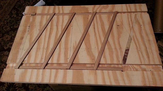
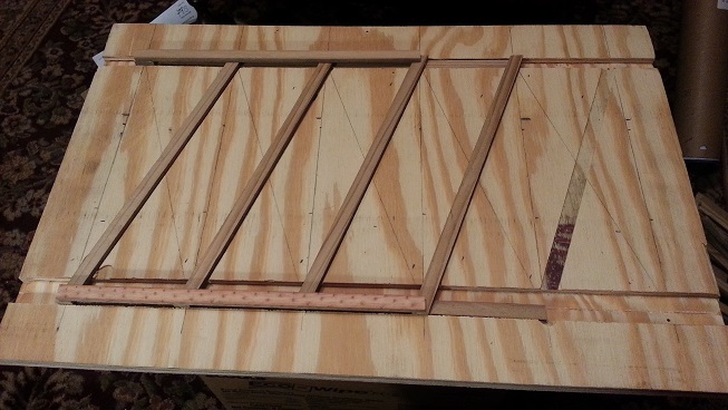
After a number of false starts, I finally came up with a final design and a jig to hold thing together for assembly, which starts with placing upper and lower members. Then the first course of diagonal compression members are placed over those.
Another set of upper and lower members is placed over those, but these are a “cell” shorter than the previous. Then another course of diagonal members, this time in the tension direction. One last layer of upper and lower members, yet again a “cell” shorter.
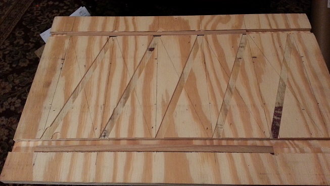
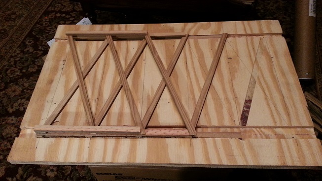
Hopefully the pictures are worth thousands of words, but perhaps I should start with how I made the jig. I learned from my experience with the trestle bent jig and started with a chunk of ¾” plywood. After carefully calculating the placement for the upper and lower truss members, I proceed to cut ½” wide slots for both members, 3⁄8″ deep, using the router.
Those upper and lower members are only ¼” thick, but the jig must be recessed enough to allow for the diagonal members to be placed over them, which accounts for the 3⁄8″ depth. Again using the router, I cut slots for the first course of diagonal members, this time only 1⁄8″ deep. I’ve never really had much success with using the router, even with a guide, so I’m a bit nervous.
Those with a keen eye will notice that I missed by half an inch on the lower slot and had to cut another next to it in the correct position. I must have miscalculated, but thankfully was able to correct for it without having to start all over again.
Building A Truss
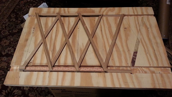
By building two of the end assemblies, one can be flipped over and placed on top the first such that the diagonals overlap and fill in where the other is missing them. A truss constructed in this manner will be rather short and somewhat useless, but it demonstrates the approach. Another picture is in order. The horizontal members are roughly nine inches apart. Where the diagonals meet them are about four inches apart. The minimum truss length is about two feet.

A truss of arbitrary length can be constructed by first starting with a pair of end sections. Any number of intermediate sections can then be inserted between the two end sections, using the same offset technique for placement of the diagonal members, except the length of all the horizontal members of the intermediate section are all identical. The intermediate sections don’t necessarily all have to be the same length
This is the modular approach I borrowed in hopes of building the bridge trusses a section at a time, then later assembling them all together into one long truss, four feet long. The jig allows me to build intermediate sections up to two feet in length. Combined with the two end sections yields the desired four foot span.
Each and every joint requires cutting a piece of the threaded rod, and that requires chasing the threads, mangled by cutting. The rods come in three foot lengths. The joints need a chunk less than an inch long. Before cutting, nuts are threaded on the rod to chase the threads after cutting on their way back off, but this proves difficult and ineffective.
While using the nuts is good enough for proof of concept, the rivet counter in me prevails. A good set of threading dies make the task much easier. The correct sized machine bolt would be perfect, but the only items available in these small sizes are machine screws.
We’ll stick with the more prototypical nuts, although hex nuts aren’t strictly prototypical either. Square nuts and square headed bolts would have been used on the prototype. Also not strictly prototypical is the way the horizontal beams are joined, but short of stamping or casting joining plates that the prototype employs, this will be close enough.
The most frustrating part of assembling a truss is having to partially disassemble the modules just to join them together and reassemble. It’s hard enough for my fat fingers to fumble with threaded these tiny nuts on the rods once, but having to do it twice or more is trying my patience.
Perseverance prevails and I finally have two fully assembled trusses. Now to join them together into the final bridge span.
Building A Bridge
The two trusses are held together by pairs of scale 12x12s and tension rods. The scale 12x12s are cut to extend beyond the sides of the trusses. Holes for the threaded rods are drilled in the ends. Threaded rods extend through the pair of 12x12s, above and below the trusses, secured by nuts and washers on the tension rods.
Sounds simple enough, but no amount of hands seems enough to hold everything together while tightening the nuts on the rods. A different approach is called for. By preassembling the pairs and rods, sliding them over the ends of the trusses, then tightening to hold everything snug works much better.
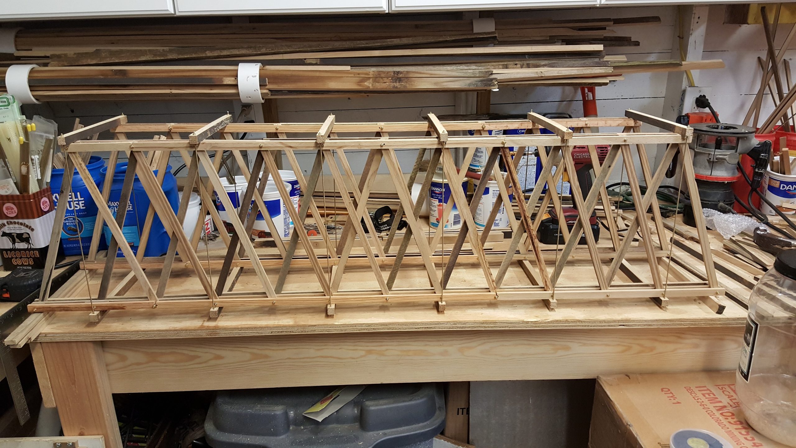
Assembly continues by just snugging the rods at first, then tightening them until they can be “plucked”, like tuning guitar strings. More like bass strings as thick as the rods are, but they still make their own music of sorts.
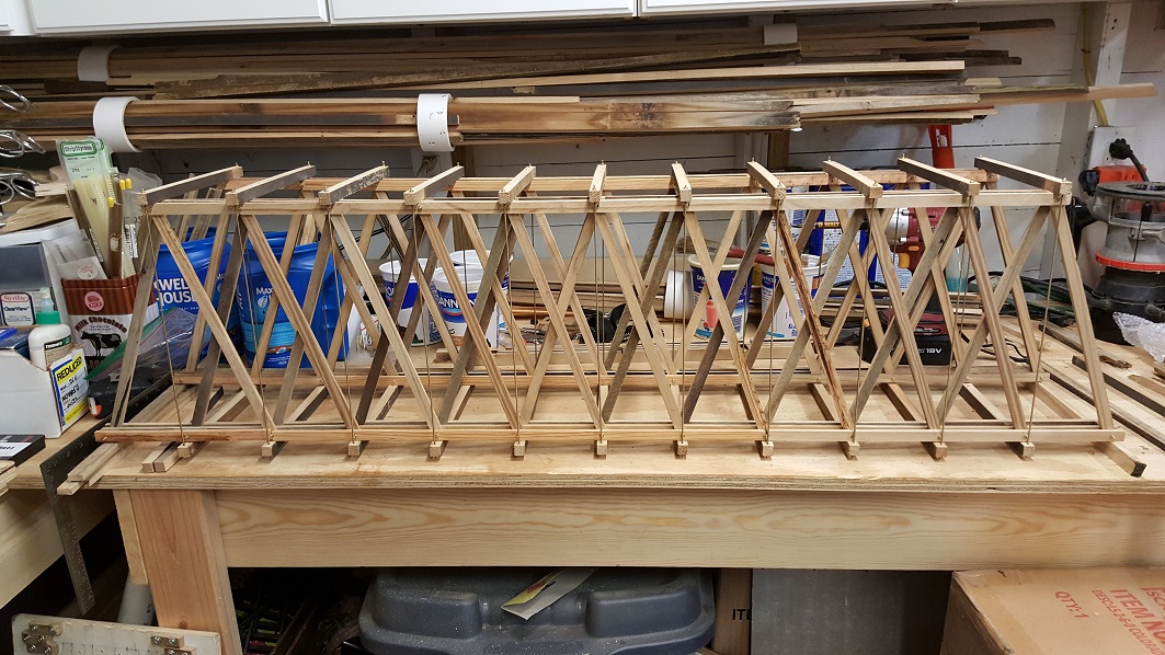
As the rods are tightened, the structure becomes more rigid, but wants to twist the tighter they get. It appears the trusses are deforming under the force. Attempting to twist things back in shape causes the trusses to deform further.
We have a bridge! Good enough for now, but there shortcomings that will need work.
Items To Address
The first issue encountered is accurate and repeatable placement of the holes for assembling the truss members. A few modifications to the jig will allow the use of my dremel drill press and a means to accurately index the holes. It should help speed up assembly, but assembly will remain clumsy and difficult using the modular approach.
Another disadvantage is joining the horizontal members “together” where the diagonal members join. A less than rigid truss assembly produced. Even though the joints are staggered, the forces applied by the diagonal members tend to force the horizontal members apart, much weaker in comparison to a single member.
Slop inherent in the modular truss approach could be overcome using a number of different approaches.