It’s Dead! 3D Printer Relapse

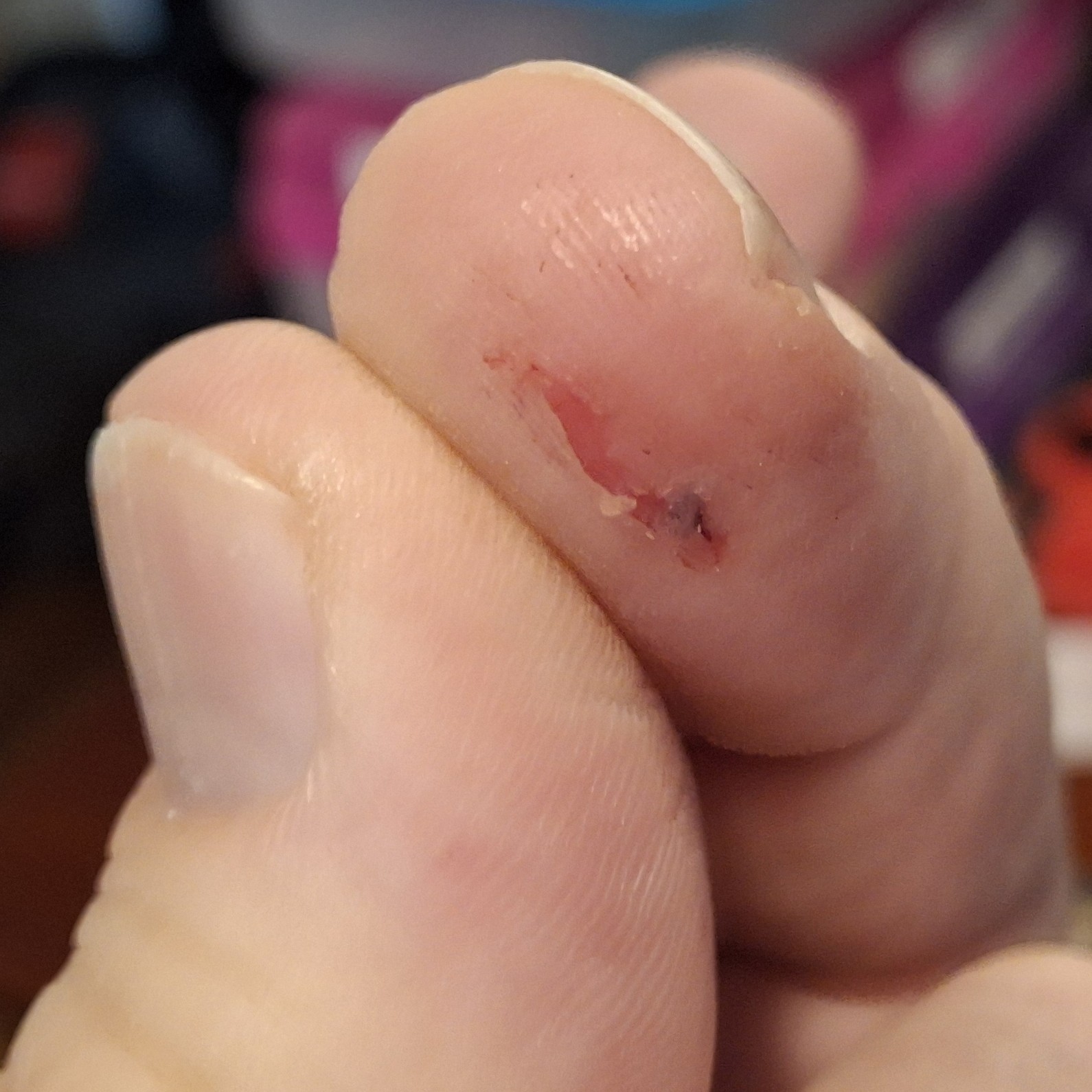
Not again! I was so happy to finally get this thing back up and running only a few months ago and it just failed on me again! Catastrophically this time, taking half my thumbnail with it! The extruder release lever broke, snapped right off, just trying to remove the filament. That sent my thumb on a rapid collision course with the printer frame. Ouch!

Blood everywhere and playing beat the clock to get the filament out before the hot end cools off, now I’m prying what’s left of the lever with a screwdriver to release it and still having to tug the filament harder than I should. I noticed it’s been getter harder and harder to remove the filament over the last week or so and should have known something was wrong.

Had I known it was going to fail I could have ordered a new extruder pre-emptively. Had I known it was going to fail, I could have saved myself some pain too. I guess in some ways I already knew it would fail, eventually, being made of plastic where metal is called for. Plastic gears. Plastic case. Plastic tensioner arm. All plastic!

The only things not plastic are the gear and idler pulley that together push the filament through the extruder. That and the screws that hold everything together. There’s the spring that holds pressure against that release arm the idler mounted on, pinching the filament against the drive gear too. It snapped off right where the spring pushes against it.
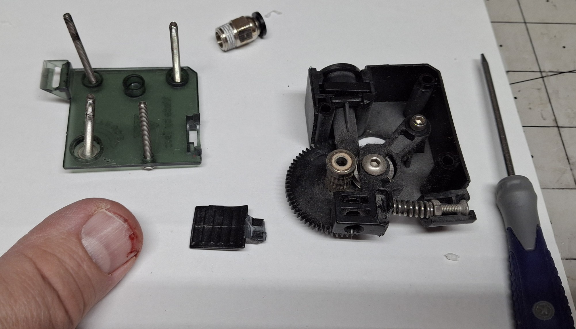
The Damage To The Extruder And My Thumbnail

Time To Rewind

Let’s rewind a bit. In my previous post, I covered the history of this Tevo Tarantula Pro (TTP) 3D printer and what it took to get it operational and back online. I’ve been using it almost daily ever since then. In fact, I’ve been using both 3D printers nearly every day. There’s a certain satisfaction from having both of them cranking out prints at the same time.

When one or both isn’t printing something, it’s almost like OCD with me, asking myself what can it be printing now? Every post since the one about getting it working again has included prints from both 3D printers. It’s uncanny how quickly that old TTP can print. I thought I couldn’t push it any faster, but I did mistakenly and it kept right up!

The new Sunlu S9+ was advertised as capable of 250mm/sec, but even when I ask it to do half that, the TTP is still faster, even though the print’s been sliced for it using slower speeds. How is that possible? Nick has a theory on that, thinking it’s built in acceleration profiles limiting the overall speed in the new one.

Turns out I was actually sending some pretty tame acceleration limits with the startup G-code. I modified the startup G-code to remove them and modified the printer settings directly with much more aggressive values, but it still seems to obey some magical built in values I haven’t been able to find. Oh well, at least it’s almost as fast as the TTP.
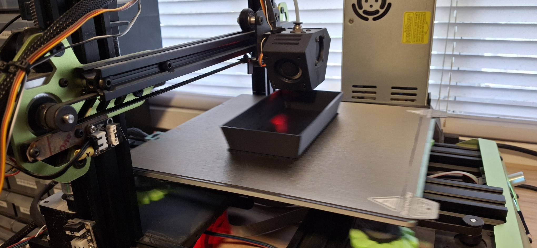
Too Fast For Even My New Phone Camera To Catch

Cranking ‘Em Out

As I said, we’ve been cranking out the prints. Between Death Trap, Death Trap Jr., and the Closet Lighting controller prints, both have been kept busy most of the time since bringing the TTP back online. I used the time between prints to make minor design modifications for each new iteration of each print then kicked off the next revision.

Of course, when it takes 8 – 12 hours to print each piece of a Death Trap it gives me plenty of time to work on other designs, and not just 3D print designs. I’ve also been working on a major refactor of how the menus and meters are handled in my Arduino sketches and libraries. The motivation is to test a new round display as a digital version of an analog meter.

But I’ll save those details for later. When I say later, I mean in a later post, once it’s all working again. To be honest, I was getting overwhelmed by the immensity of the project and had to step back from it for a bit. Not going to list all the priority items I’ve already discussed in recent posts. Let’s just say the Ultimatum of end of August is quickly approaching.
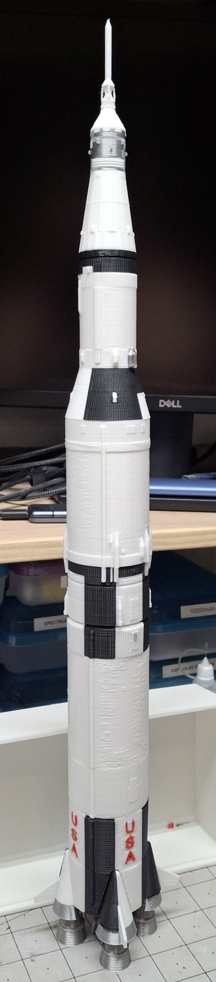
The Saturn V
The Saturn V

My Saturn V Tribute

Between the Ultimatum and the constant media circus lately, even preempting the recent 56th anniversary of men first walking on the moon, July 20, 1969, I decided to print my own Saturn V as a tribute. I needed a breather. An escape from all this necessity and media insanity and it seemed like the perfect project.

Most of the parts are either black or white, with some parts in metallic silver, and a little red thrown in for the letters. The new printer is already loaded with white and the TTP with black, so I sliced the parts based on what printer had what color. Once all the black parts were printed, I loaded up a half spool of metallic silver, a.k.a. silk silver.

These were the engines, heat shields, the service module and few other interstage parts. The engines had the most supports I’ve ever printed by far. Probably more material in the supports than in the rocket engines themselves. Those supports had to come off in layers, peeling them off until getting down to the final course that snapped right off.

I should note these STL files are from a third party source and it took some doing to get them sliced for my printers. I generally design parts without the need for support unless absolutely necessary. I probably would have made the engine nozzles separate from the combustion chamber and turbo pumps and stuff so they can be printed flat on the build plate.

Finishing Touches

Anyway, I loaded up an old spool of what was left of 3D Solutech red. It was still coated in dust from sitting out in the office on the old closet rod arrangement I had sitting over the printers. The idea was to make it easy to load a different color by just sliding the desired color spool into place and loading it.

That was before I knew about the effects of moisture on the filament and filament driers. I loaded it in the filament drier and let it drive out as much moisture as it could first, before loading it in the TTP. Long story short, I thought I did a pretty good job getting rid of the dust. Not so much.

And it wasn’t apparent it was an issue until the symptoms of a clog started to manifest themselves later. The red letters were the least of my worries. Or so I thought at the time. Once they were done printing, I decided to print the base in red too. Think I putting the finishing touches on the Saturn V I literally put the finishing touches on the printer too.
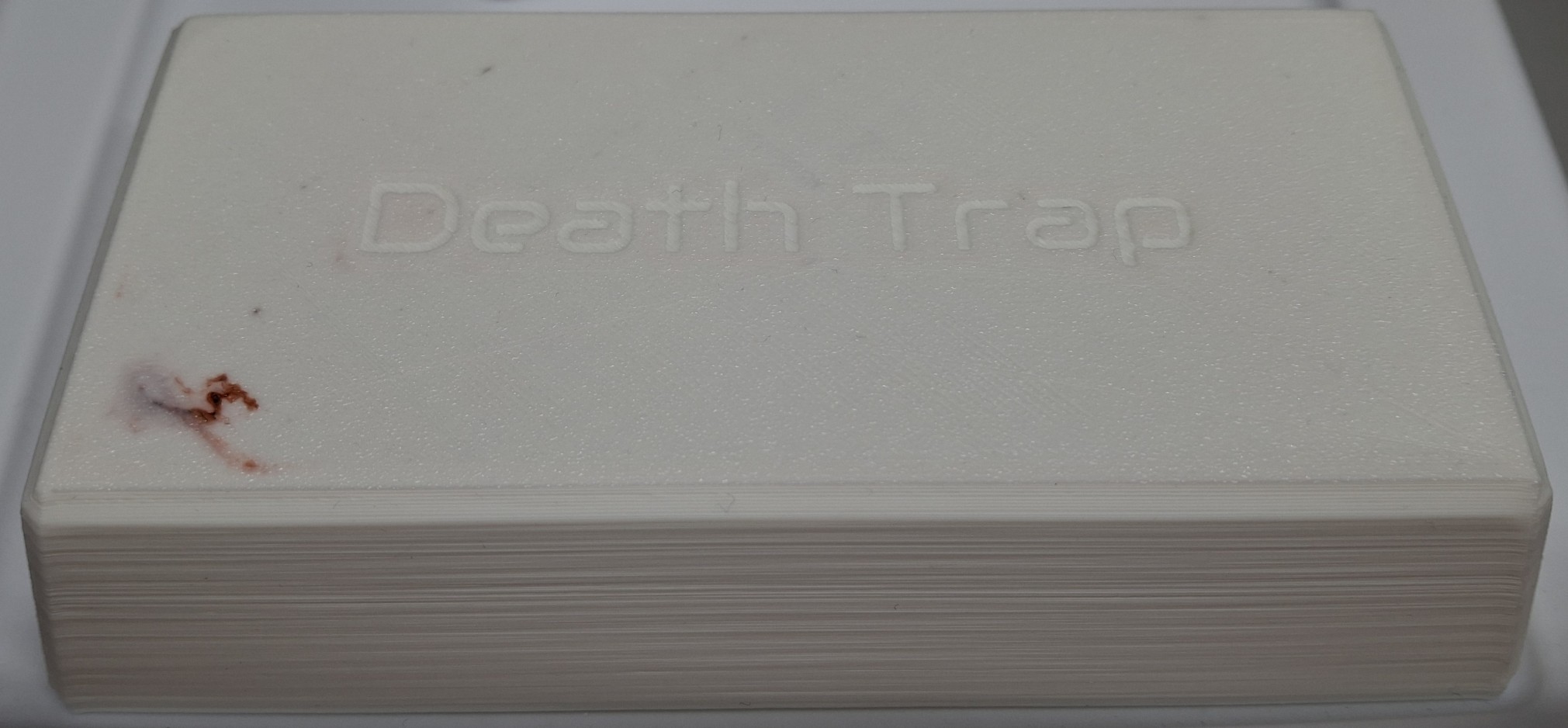
Nice Red Pimple In A Sea Of White

Symptoms Adding Up

I originally printed the Death Trap Jr. in black, but it looks like exposure to the sun is enough to warp the plastic. I decided to print a white one with the filament left on the spool, starting with the lid. My first indication there was trouble brewing should have been how long it took to clear the red out of the hot end and replace it with the white.

It was pink for much longer than I’ve ever had to run the new material through to clear out the old. As it was laying down the first or second layer of the lid, all of a sudden it “burped” out a red “pimple”. That is to say a big glob of red that must have been still stuck in the hot end, now surrounded by a sea of white on the build plate.

That should have been my heads up. Between pulling out the filament getting harder and harder and now this, all the signs of a hot end clog were starting to come together. I thought there was enough filament left on the spool to print the base too, but I was wrong and had to pause the print to load the new Elegoo PLA+ filament.

Trouble Brewing

It was all I could do to pull the remaining filament out. I had ordered four spools of the Elegoo PLA+ in white, and loaded a spool as a test and a comparison to the white Sunlu PLA+ I’d been printing with. The TTP was reloaded with the new white and the print resumed. It seemed to print fine. If anything, it’s a slightly brighter white than the Sunlu.

Then the extruder started making that skipping noise, but given an assist from me in the form of a little extra push on the filament, it seemed to smooth out things for a while as the printing continued. The base finished and I thought nothing of it, preparing to pull the filament back out to store it in the drier until the next print.

That’s when it happened. Right around 9:00 PM Saturday night. I could not get the filament to pull back out. Pushing on the release lever didn’t seem to do anything. Until it snapped off, taking part of my thumbnail with it. So now we’re all caught up after the rewind. So why bother pulling the filament out at all?

After having the filament just randomly snap apart when left out and exposed to the humidity over a period of time, I decided to start removing the filament when the last print for the next few days finished. This allows the flexibility of keeping the spool in the drier or storing it in one of the sealed bags and loading a different spool, and whenever needed.
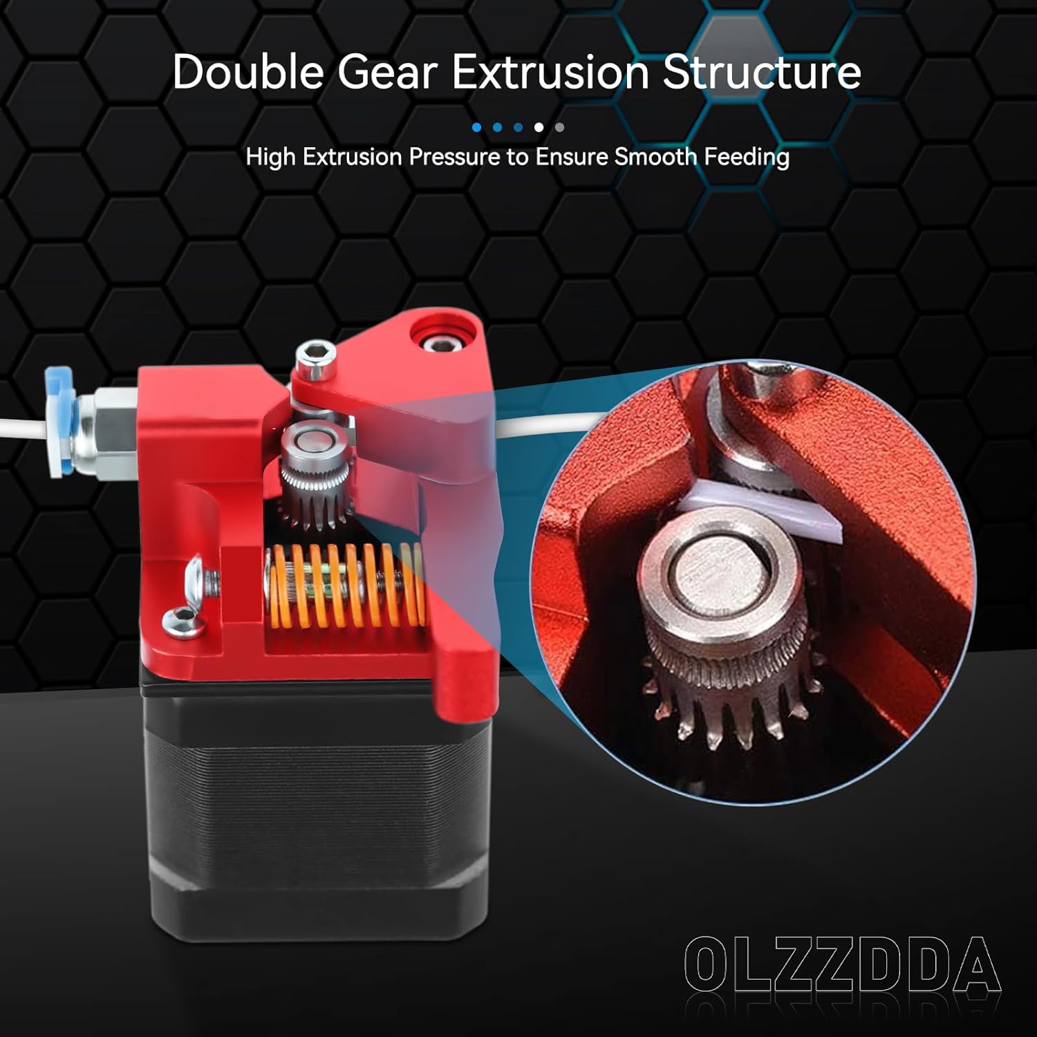
Replacement METAL Dual Gear Drive Extruder

Where Do We Go From Here?

Obviously I need a new extruder. I’m not sure if I can even still source the original, let alone find one that isn’t already on its way out like my old one. Nick recommended a dual drive replacement like the one he got for his printer recently. It’s all metal, with two opposed drive gears rather than one and an idler “pulley”. The frame is all anodized aluminum.

I ordered one from Amazon and it arrived Sunday afternoon. If I have any complaint it would be the total lack of assembly instructions. I had to closely scrutinize the limited number of pictures on Amazon to piece together how things fit and where.

But before all that, I had to remove the plastic gear pressed on the stepper motor shaft. Thankfully there was enough clearance between it and the face of the motor to get a pair of screwdrivers behind it and pry. I only flung it on the floor in spectacular fashion once… When the screwdrivers finally lost their leverage, the adjustable wrench finished the job.
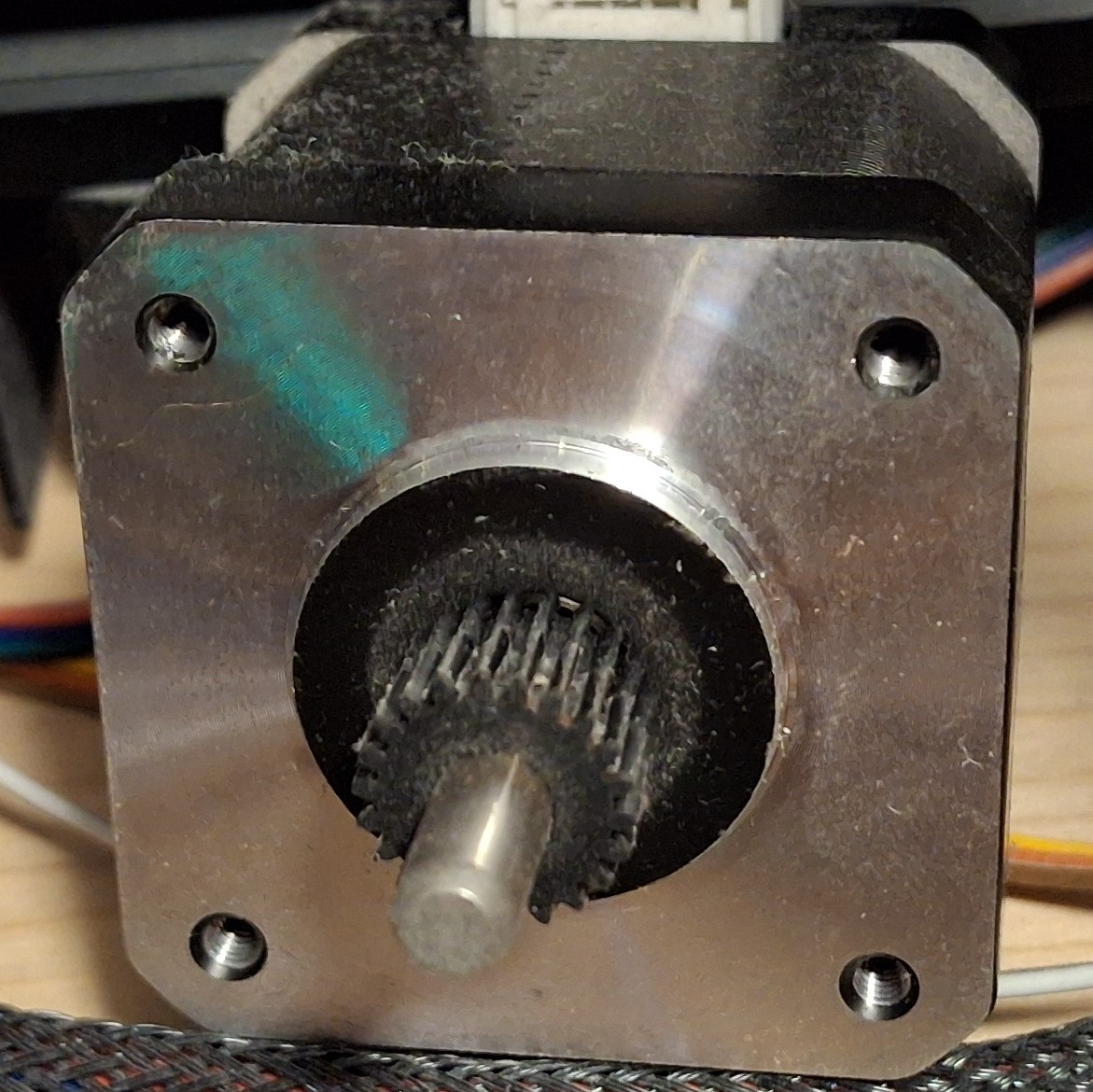
Old Pressed On Plastic Drive Gear

Fitting The New Extruder

Now it’s time to get the new extruder drive gear on the stepper motor shaft and roughly aligned with its companion on the rest of the extruder. Running the set screw down will keep it in place until final adjustment can be made. Now we can fit the new extruder to the stepper motor, separated by the mounting bracket. I only screwed up the orientation twice…

First I managed to get it 90° off, thinking the release arm worked opposite of what it actually does. The next time I somehow managed to get connector on the stepper motor facing away from the cable. Each time it had to come all back apart and the screws totally loosened and moved with it.

After a few choice words, I finally get it all put together and ready to test. Well, once I adjust the drive gear alignment on the motor shaft that is. It’s already a miniscule set screw to begin with, and it’s a good thing the hex wrench is so small and flexible, because trying to get it in the set screw would be impossible without flexing it, even with a ball end.

With that done and out of the way, it’s time to load up the filament and do some testing. And instantly I’m getting that skipping and nothing out the nozzle… So much for the new extruder fixing the problem.

Nick Lends A Hand

Nick was kind enough to take a look at it with me after supper. I had basically shut down the printer and left it off until I was ready to test with the new extruder, not giving the idea of a clog a second thought. Until now.

Nick realizes it’s taking way too much force to push the filament into the hot end. Not much if any plastic is coming out the nozzle. That would explain why the extruder is just skipping. Then he asks if I recalibrated the extrusion rate. I told him I had not. Not being able to extrude makes it difficult to measure how much gets extruded to adjust the rate.

Looking at the old extruder, it’s readily apparent that I need to make at least some adjustment since the old one had a gear reduction and the new one is direct drive, right off the stepper motor shaft. Oopsie. After “guestimating” the reduction ratio, I make a quick divide by four change, from 408 to 102. Still skipping though.

Poked the nozzle. Nothing. Took the nozzle out to see if it could be reseated without having to tear down the hot end again. I probably just made things worse by giving the molten plastic all the room it needed to fill that void, guessing that “overdrive” forced the molten plastic out between the bowden tube and the nozzle in the hot end causing a clog.

A New Hope

After having torn down the hot end twice, and finally getting it fixed only a few months ago, I NEVER want to have to do it again. But it looks like that’s what it’s going to take. That’s it for tonight. I thank Nick for his help, then shut down the printer again and leave it off until I have more time. Do I need yet another new hot end or can just clear the clog?

Tearing down the hot end takes up my entire work cell to lay the printer on its side to be able to get to everything on the printer, short of standing over it while it’s sitting on the shelf and having to turn it to reach behind it. I need that work cell for my work laptop during the day. I can’t leave the printer torn down with parts strewn everywhere. It needs to wait.

Later in the week I was chatting more about it with Nick and something he said about the opening through the hot end being as big as the bowden tube triggered a thought. Will simply pushing the bowden tube through the hot end clear the clog? A quick search of the waste basket tells me I already threw out the old tubing. Damn!

I don’t really want to dig out the new roll of tubing again just to cut a short piece. Then I remember I have an assortment of solid brass rods. Is there a 2mm rod? Bingo! If it’s not 2mm, it’s 5⁄64″, and at least 100mm or 4″ long. If anything’s pushing the clog out, this ought to work, as long as it’s not too big around.
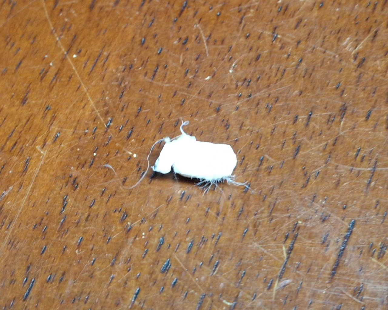
The Culprit, A 2mm x 6mm Plug

We’ll Do It Live!

It’s a perfect fit! It quickly and easily frees a 2mm round plug ~6mm long. It pops right out onto the build plate! Nice! Not having to tear down or replace the hot end is even better! I should mention I’m doing this while the hot end is live, at temperature set for 210°C. Otherwise the plastic would be solid as a rock and stuck to the inside of the hot end.

Time to thread the nozzle back in, as fast and as far as I can by hand until it gets too hot to touch. The small adjustable wrench tightens it the rest of the way in. Next is to thread in and tighten the retainer fitting for the bowden tube coming from the extruder. Last step is to push in the bowden tube until it seats against the top of the nozzle.

Basically the bowden tube has to fit tight against the top of the nozzle to prevent the molten plastic from oozing out around it and causing a clog in the hot end. To get that tight fit means the end must be cut absolutely straight. There’s even a special cutter tool to do just that. And you’d better believe I used mine!

With everything buttoned up, I load up the black filament, pushing it through the new extruder and all the way down the bowden tube until I feel the resistance of the nozzle. From there I command OctoPrint to extrude 50mm of filament and… Still skipping and very little plastic comes out the nozzle. Again?
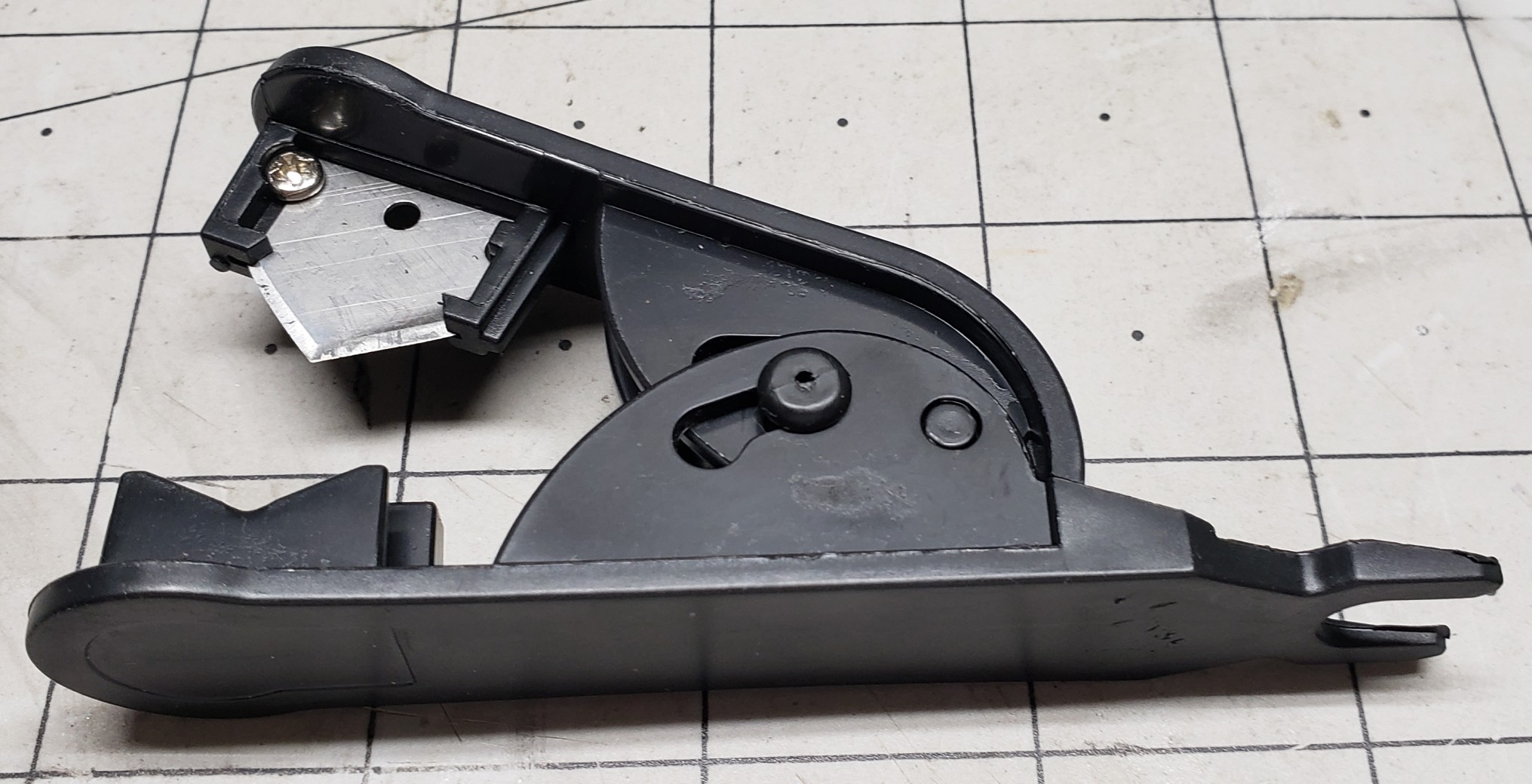
Bowden Tube Cutter
Bowden Tube Cutter

We’ll Do It Again!

Let’s do this all over again then. Remove the fitting and bowden tube. Remove the sizzling hot nozzle with the wrench. Push out the clog with the brass rod. Put it all back together again. Same thing! Still skipping and very little plastic coming out the nozzle. What is going on?

Did the hot end somehow manage to clog again? How is that possible? I’m beginning to suspect the bowden tube isn’t fully seated on top the nozzle or the new nozzle is somehow clogged already or both. I try to mark where the bowden tube sits relative to the top of the fitting, but even permanent marker doesn’t stick to teflon tubing.

Let’s do this all over again. Again. This time I switched to another new nozzle, guessing not clearing the clog first just clogged the new nozzle too. This time to ensure the bowden tube was indeed fully inserted and sitting on top the nozzle I inserted it first, before screwing in the fitting and tightening it down. It definitely went in further than before!

It’s Alive! Again!

It’s alive! It’s extruding like it should! Not skipping at all! That must have been the problem, another clogged nozzle and the fitting interfering with the bowden tube and constraining it enough so I wasn’t able to insert it enough to fully seat on top the nozzle. Definitely need to remember to insert the bowden tube then install the fitting next time.

I’m so happy that it’s working again and cannot believe it wasn’t something more serious. Had I known it was going to be a simple fix I wouldn’t have waited all week to try it. But again, until Nick mentioned about the bowden tube passage through the hot end, I wouldn’t have thought to work on it while it was still sitting on the shelf.

Removing a few easy to access parts and pushing out a clog with length a brass rod is certainly easy enough to do just that though. Thankfully I didn’t wait for the weekend to try it. But before I start doing backflips to celebrate, it’s time to actually calibrate the extruder steps and run a test print.

Turns out my guess of 4:1 reduction was off, more like 2⅚, but now when I ask for 100mm of filament to be extruded I can be confident it is. I fire off a test print, crossing my fingers I won’t have to recalibrate the Z offset too. The closet lighting battery cover prints fine, although I may have heard the nozzle lightly grazing the texture of the build plate.

One More Time

I fire off another test print, this time another closet lighting switch box lid since the latching tabs were broken off the old one. Do I need another closet lighting switch box? No. Will it be nice to simply swap out one that needs charged with one that’s already fully charged and ready to go? Yes. Yes it will.

I’m not taking the time to put another one together right now though, but at least I’ll have all the parts I need to put one together when I’m ready to. With both the test prints finished and looking good, I’ll just need to keep an eye on the Z offset, looking for a telltale groove forming in the texture of the PEI sheet.

Desperately trying to find something else to print so as to keep exercising the printer but coming up short. Already have more than enough run in stands of various colors, like black, navy blue, and white.

Speaking of Navy Blue, that’s another 3D Solutech color I can’t seem to match and I’m down to the last few layers on the spool. And it was just as dusty as that red was that I’m pretty sure caused the clog in the printer.

Lessons Learned

I learned a number of things from this one. A number of things that I should avoid or do differently in the future. And I learned a method that will make it easier to remove another clog in the future if it happens again.

The first is even though I think I got all the dust cleaned off from those leftover 3D Solutech spools, they aren’t clean enough to avoid a clog. Maybe I can rinse them off then bake them in the drier to drive out the moisture. I hope it doesn’t totally ruin the filament, but at this point, it’s already ruined unless I can find a better way to clean off the dust.

The next is to insert the bowden tube into the hot end fully to ensure it’s flush against the nozzle before installing the retainer. And this time I learned something new, an easy way to clear a hot end clog without having to tear it all apart. Had I known this before destroying the original hot end the first time I had it apart, I could have avoided having to replace it.

Another thing that I learned before this happened is moisture is the enemy when it comes to 3D printer filament. I learned this the hard way when the exposed filament loaded in the printer would just randomly snap, becoming brittle from the moisture. The problem is the remaining filament is just as brittle and removing it may be difficult or impossible.

So Long Solutech

As an aside, 3D Solutech used to be my go to filament, made in many different colors. A much larger range of colors than most every other manufacturer. For example, Wheat, Skin, Denim Blue, Navy Blue, Merlot Red, etc. Their Merlot Red is a very close match to the maroon color of the AT&SF passenger cars while their Navy Blue a close match to B&O Blue.

Their products are no longer available since they went out of business years ago. Amazon’s available stock lasted for another year or two until it was finally depleted. I still have a large stock, vacuum sealed in the box, but once it’s gone, it’s gone. Like the Navy Blue, all I have left is a few layers on the spool, maybe one or two.

The only alternative is to paint the parts, in this case with B&O Blue, a.k.a. Bando Blue. But even getting matching paint has become more difficult as major manufacturers have left the market, citing low sales volume. So now everyone’s in the same boat as those who modelled a road name with colors no one carried, having to hand mix their own.
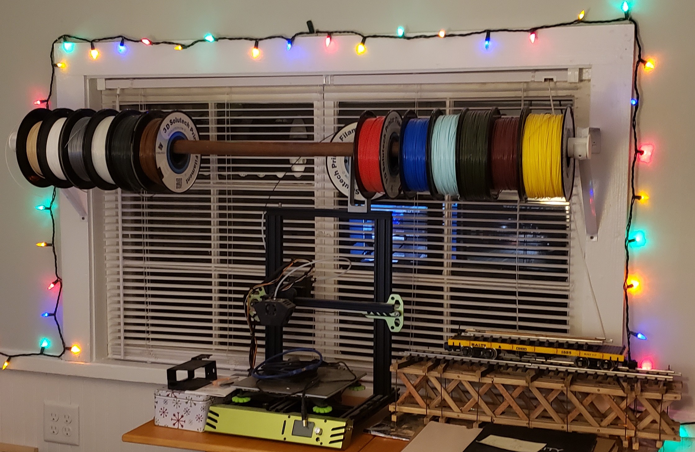
Ill Advised Attempt To Keep All Spools Available

Live And Learn

I also have a large stock of already open, dust impregnated spools that used to sit out on a wooden closet rod above the printer, exposed in the office environment, some for years on end. I’m really hoping the idea of rinsing the filament clean is a viable method to reclaim them. We shall see.

I’m faced with the prospect of just throwing them out. For those near empty spools, it’s not so difficult, but the nearly full ones I’d really like to save if at all possible. A dozen spools at $20 or more a spool is a $250 loss. I’ll learn my lesson the hard way it seems.

But it’s more than just the money. It’s the lack of suitable replacement color options. Sunlu has a large selection of colors, but nowhere near as many as Solutech offered. My favorite color to print prototypes with was “Mint”, an Aqua shade, but lighter. Kind of like powder blue but with more of a greenish tinge added.

Fringe Benefits

Oh well. At least now the filament sits in a filament drier meant to drive out the moisture. As a fringe benefit of being totally enclosed within the drier box, it also protects the filament from dust. As I said, the only issue is with the exposed filament if it isn’t removed from the printer after the last print for an extended period of time.

For now I should also learn to just take the win and move forward. After a relatively simple fix, I’m once again blessed with a working printer. Two working printers for that matter. And both are sitting idle, awaiting their next assignment, with exposed filament until then!

I hope you enjoyed this post and the “surprise” ending of a not dead again printer. Hopefully by the next post I’ll have the design for those concrete molds for the switch ladders. We shall see. Stay tuned, more to come.
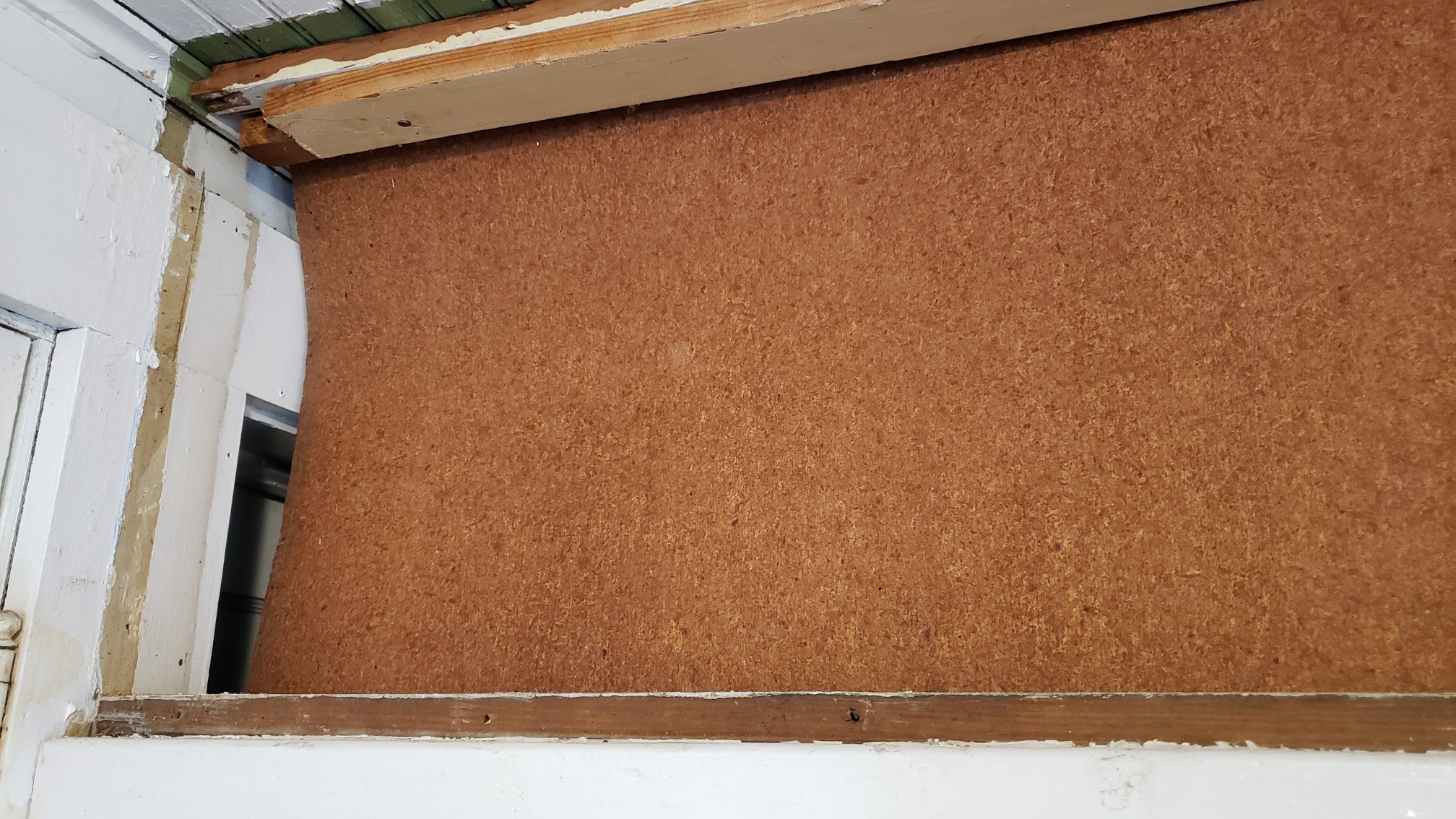


Closet Lighting

I’ve made small progress on many different things today. Not as much as I wanted to get done, but I never do. The one thing I really wanted to get done was cleaning out my bedroom closet the rest of the way. There’s kind of a short story surrounding that, so I’ll try to keep it brief…

When we remodeled the back porch, there was a lot that needed done. It was a disaster. Everything was covered with cheap, thin paneling that may have been tempered Masonite™ at one point, but now brittle and crumbled in your hand. Not only did it cover the walls to the outside, but it also formed the bedroom closet walls. It had to go.

There was also a makeshift passthrough door in what was supposed to be a wall between the laundry room and the extra storage room off what became my bedroom. That extra room became data central. Not all at once, but over repeated incarnations to what it is now, each time to increase and better organize storage as well as provide better utility.

Old Craptastic Closet Wall Panelling

After tearing out all that crappy paneling, and the bedroom closets, and studs that framed them, it really became one big pass through until I rebuilt those closets. I used bead board, with the outside facing the back porch painted white, and the inside left as natural wood. I even used cedar for shelf cleats and the closet rod hangars. Absolutely beautiful!

Closet Lighting

The only thing missing is lighting. There was no provision for lighting in the original closets either. Probably a good thing too considering most of the house power came from one of those ancient, original knob-and-tube wiring feeds. One spark and all that crappy paneling would have lit up like tinder and burned the house down!

Ann got around it with a battery powered “tap” light stuck on the bead board ceiling in her closet. I could have installed light fixtures and surface type switches with that flat, snap conduit, but we had already completely rewired the house long before doing the back porch and rebuilding the closets. Battery power it is. Then it hits me…

Why not use an arrangement like the office lighting strip? I grabbed my tape measure and verified the closet is a little more than 38″ wide. Wide enough for one of the two segments in the LED office lighting. The only difference is the office lighting has a dedicated mains power supply supplying many amps, 6 or 8 amps @5 volts IIRC.

The closet lighting will need to run on rechargeable battery power with a limit of about an amp. I have a couple of leftover passenger car lighting 3D printed battery boxes, already wired up with a 2000 milliamp hour cell, ready to go. But that would only be temporary.

Dual Strip Office Lighting

Another Lighting Controller?

Yes, another lighting controller. I really need a bigger switch, housed in a removeable box that can be moved to a charging station. I’m already behind the 8 ball on getting other 3D print designs finished and really don’t want to add yet another to the list. For now, just the ability to unplug the LED light strip from the controller box will be good enough.

I have enough of the extruded aluminum channels with diffusers to make up another segment. The nice thing about using a 3′ segment like the two that make up the 6′ light in the office is I can reuse everything from the office lighting sketch with minor modifications to the configuration and web page to support just half, 55 rather than 110 LEDs.

Each pixel has it’s own red, green, and blue LED, each consuming ~20mA each, plus whatever the consumption of the single control chip per pixel is. Let’s say 60mA per pixel as a nice round figure. The bad news is all 55 pixels on at the same time at “full tilt” will consume 3.3 amps at 5 volts! Our poor little passenger lighting setup will handle maybe 1 amp.

Thankfully the lighting controller can set them to ¼ power to bring consumption back under an amp. I was hoping to put together the new lighting segment tonight, but I forgot these extrusions are a meter long (39.36″), not 36″, and need cut to length. In any case, it’s a tomorrow thing.

It’s a Tomorrow Thing

My thought was just use the table saw with the miter gauge to trim the aluminum and diffuser to length together. Easier said than done with the garage in the state of disarray it’s in, stuff stacked on the table saw and strewn about the floor and everywhere. Hacksaw it is. A quick file to remove the burrs and it’s time to stick on the LED strip.

Once I’ve soldered the pigtail connector to the LED strip, I prep the extrusion with an alcohol pad then remove the protective strip from the double sided sticky backing, a little at a time, while placing the LED strip against the extrusion and pressing it down in place. With that done, it’s time to add the diffuser and end caps and give it a test.

I already modified the sketch config and HTML page to match the “half” office sized LED array last night. As I feared, the battery power gives out once a certain brightness threshold is reached, resetting the Arduino. Time to regroup. After some figuring, I decide to split the 55 LED strip into two, a main light of 30 LEDs, and an under shelf unit of 25 LEDs.

Another hack job, literally, with the hacksaw. Time to solder on another pigtail to the second LED strip and add a harness to another Arduino then program it for the second light strip. Also need to reprogram the original to have fewer LEDs and a new HTML control page as well. Those edits are fairly quick and my soldering job is soon tested.

Repurposed Passenger Car Lighting Controller

It Ain’t Pretty

The original idea was to use one of the spare passenger car lighting battery boxes to power and control these things. But now that I need two of them, things are getting complicated. Add to that the tiny slide switch used to power on the unit is difficult to find, let alone know which way is on if accidently left on and the battery goes dead.

It’s not a deal breaker, but it could certainly be much more user friendly, and obvious which way is on. I used double sided tape to stick the battery box to the wall of the closet and routed the wiring harness I assembled to connect the LED strip to it. After drilling pilot holes and securing the mounting clips with screws, I snap the extrusion in place. Time to test.

It works great, but it ain’t pretty, and it suffers from all the drawbacks I already mentioned. Unfortunately, recharging it was an afterthought too. At least it became apparent it was once I realized where I stuck the box to the wall didn’t allow access to the existing charging port. Now I get to gut the thing and pull out the battery every time it needs recharged!

Add to that the placement of the LED strip at the top of the closet leaves a rather pronounced shadow beneath the shelves. That’s where the second strip comes in. It will mount beneath the shelves to illuminate anything beneath them. Once I attach the mounting clips and snap it in place that is.

Best Laid Plans

Originally I didn’t plan on a light under the shelves since all it would do is backlight the clothes hanging in front of it. Now that I’ve cleaned out the closet and donated everything that didn’t fit, I’m left with one polo shirt and my motorcycle boots. There’s no reason to leave that polo shirt hang in the closet and gather dust since I no longer need to wear it to work.

I work 100% remotely now and I’ve only needed that polo once since starting this job. So now it’s folded up in my dresser. Beyond all that, it’s not long before the gutting to recharge the battery renders the battery box inoperable. The original idea of reusing what I already have is quickly dissolving into a new design adventure.

Not what I wanted at all. In fact, it’s exactly what I wanted to avoid. Certainly nothing I have time for, but it needs done nonetheless. A couple of design decisions later and I have the the HUGE 10,000mAh batteries out along with their dedicated power bank charge controllers. After a few charge and discharge cycles, I remember why I mothballed these things.

It takes hours to get to 75%, then minutes to reach 98%, where they sit for a long time before reaching 99%, then 100%. They certainly don’t garner trust in the charging readings, being the finest quality Chinesium, but they do have a nice remaining charge display and can provide more than an amp of current.

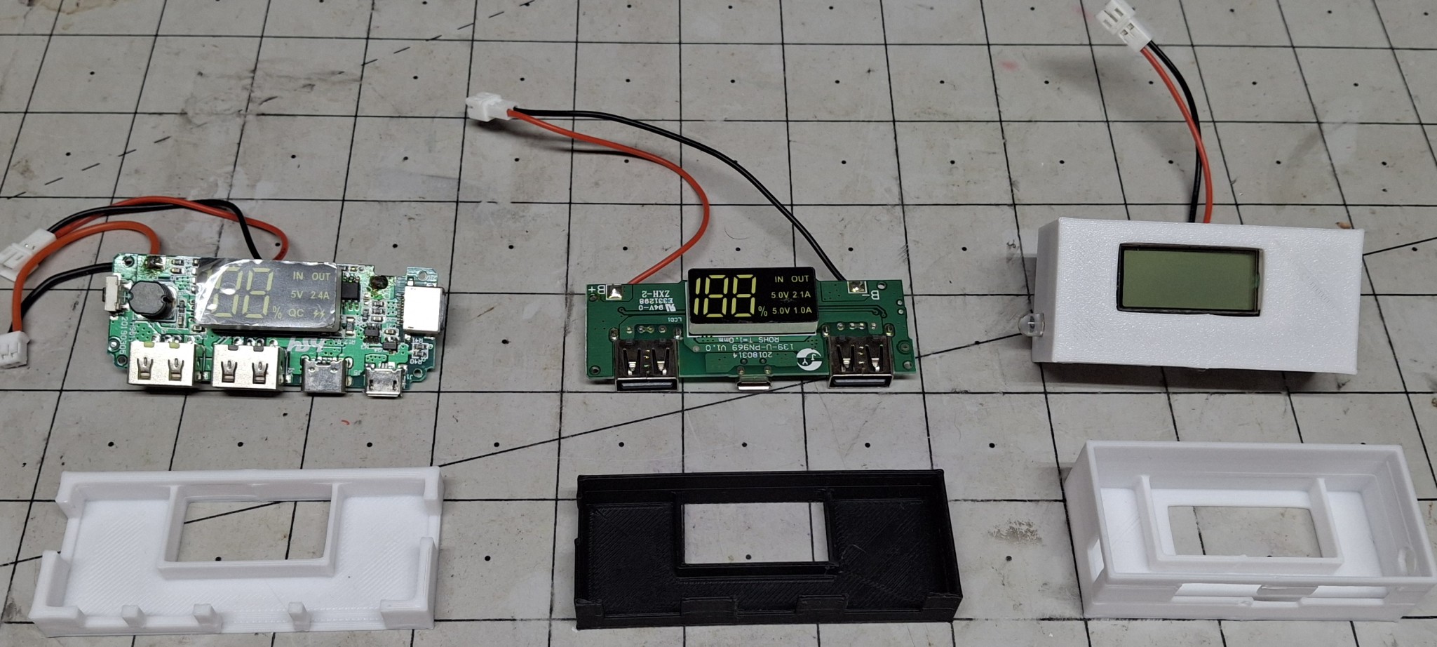
Three Styles, Newest To Oldest From Left To Right

New Designs?

Looks like I’m designing a new battery box with the dimensions of a standard switch box to hold the HUGE battery and switches big enough to be seen. The problem is I have so many different types of dedicated charge port (DCP) controllers, it requires multiple designs.

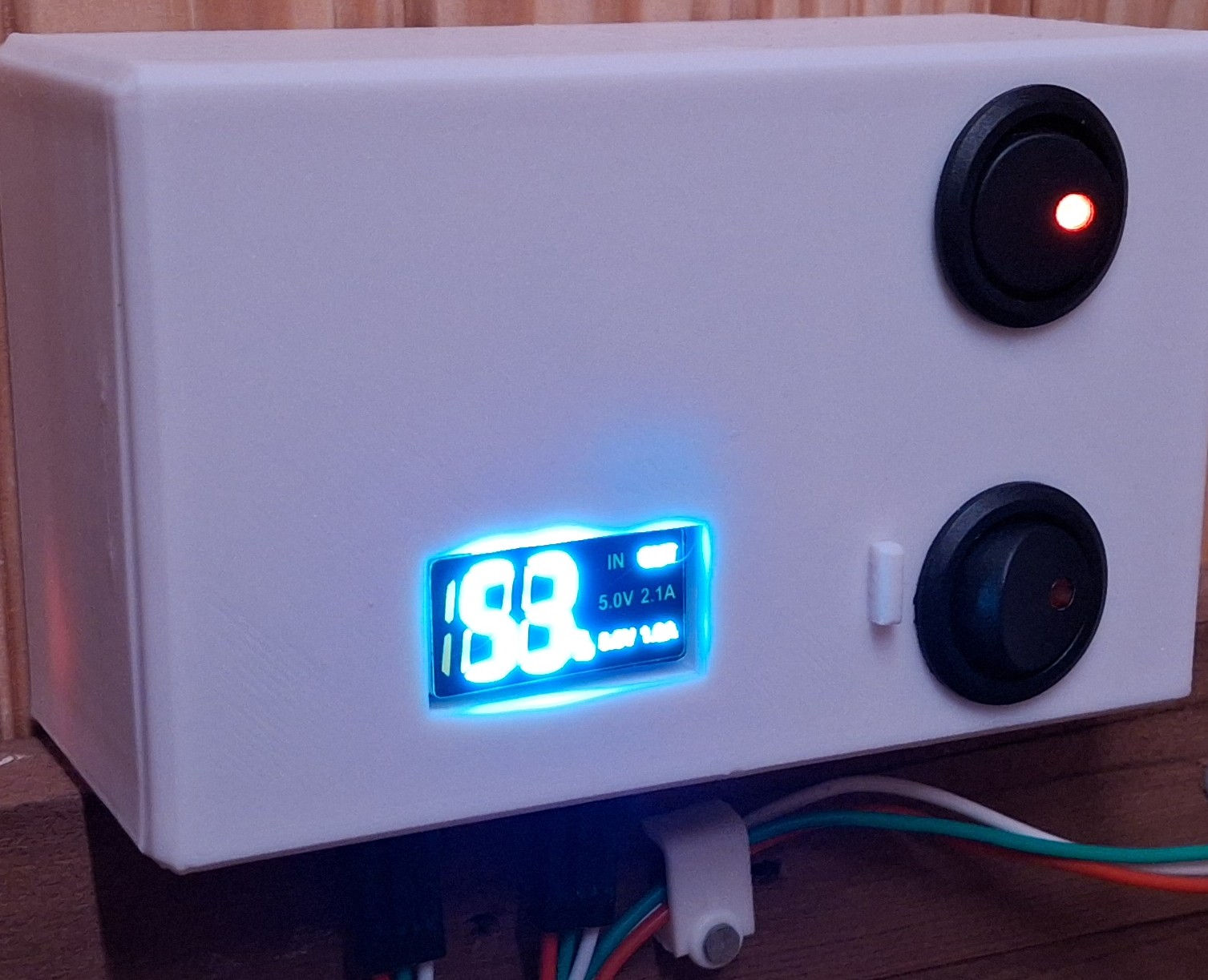
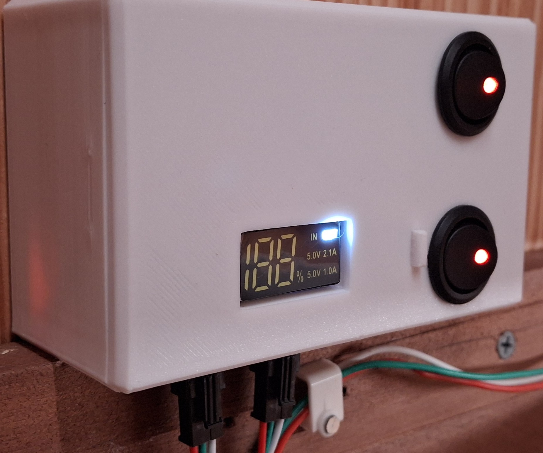
Basically I have three styles of DCPs to worry about. The first has one of those bright white LED “flashlights” that turn on when you press and hold the button. The next an older style twin USB A output with a single USB micro charge port. The third is a newer, high current twin USB A output with USB micro, USB C, and Lightning charging ports.

I chose the second style for the prototype design. The flashlight version is an LCD with a bright blue backlight but it suffers from the LCD off axis lack of viewability issue. The other two have bright white LED displays. Much easier to read without the off axis problem. The first iteration has half the access opening in the “case” and the other half in the “lid”.

The only problem with that earlier version is that to be able to provide access to the charge port from the bottom of the case, the wakeup button is on the opposite end from the outside of the case. After trial and error and three or four iterations trying to come up with a feasible mechanism to remotely push the button, nothing is working reliably.

Double Whammy

After trying to look up the specs on the unit, it becomes apparent it’s no longer available, superseded by the newer, high current version with more charging port options. So that coupled with the button on the wrong end is the double whammy. The newer unit has the button on the opposite end so it can be accessed from the outside of the case.

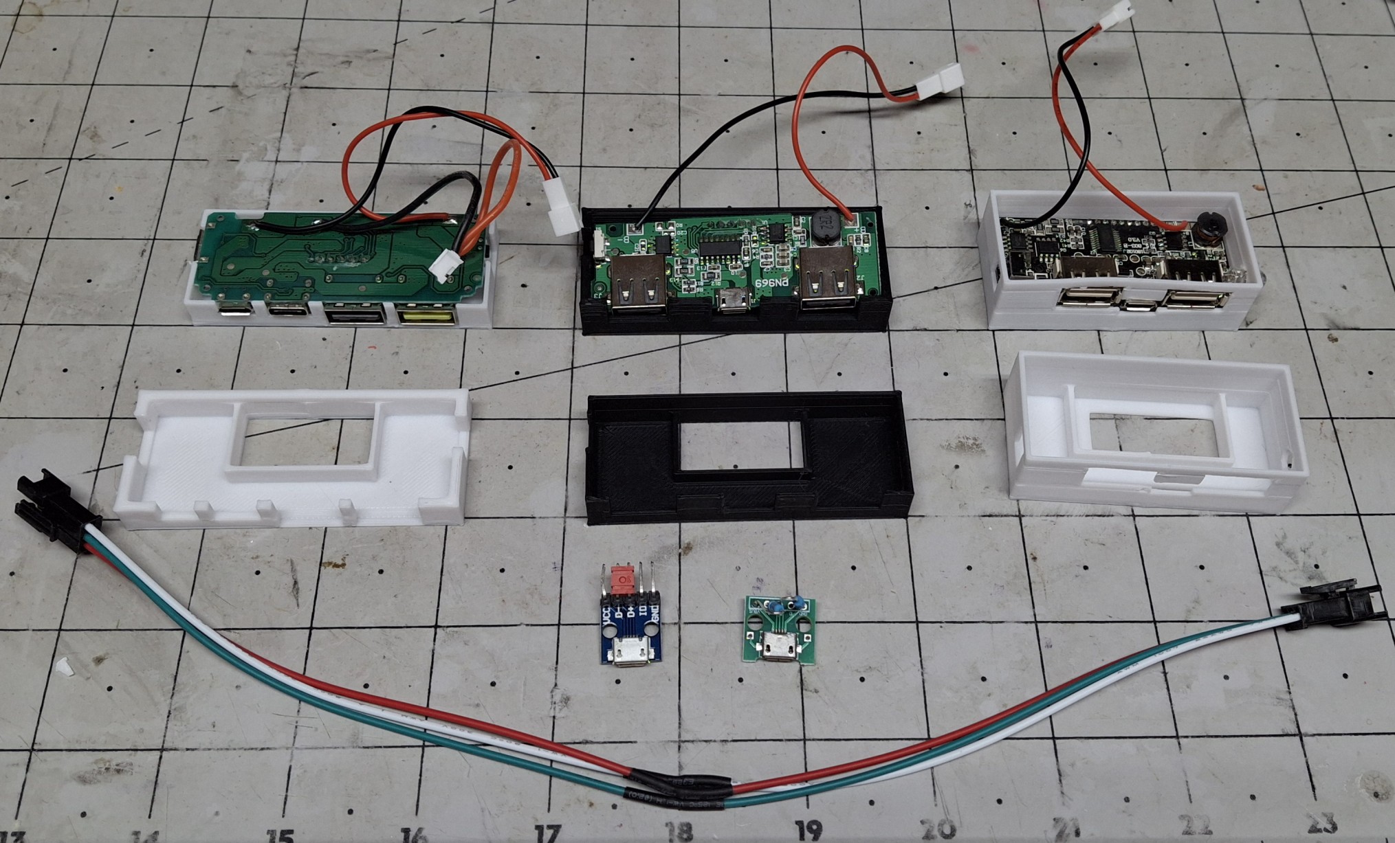
Not wanting to give up on the older version, I decide to go with a “universal adapter” approach where the case and lid have cutouts in the proper location for access to the USB A and charging ports, but the specific access port locations are contained in an adapter that attaches to the lid. It doesn’t seem all that important now, but boy am I glad I did it that way!

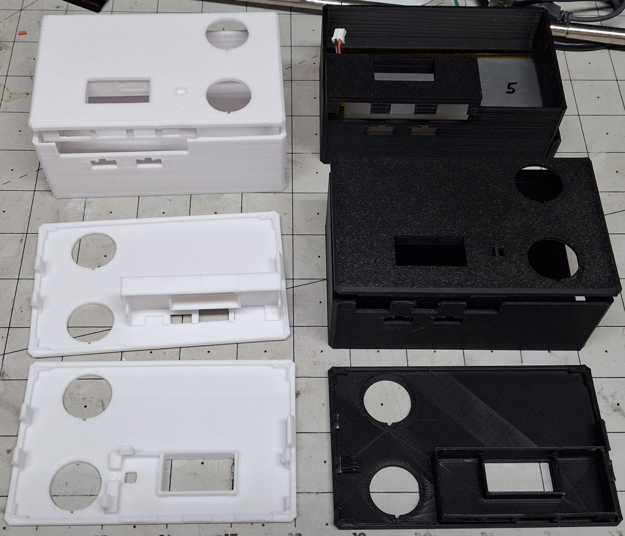
After printing countless iterations of both adapters, I reach the final designs. The case has an access “hatch” to allow sliding in that HUGE battery with a snap in cover to keep the battery from falling out. The lid provides openings for two round LED rocker switches to snap into.

Various Iterations Of Cases And Adapters

The Final Design

The final case design simply allows a generous opening for any port configuration of the chosen DCP. Previously the case and the lid both contributed to the port access closure. The adapter is now responsible to “form fit” and fill in around them. The case also provides openings to snap in two of the standard black three pin connectors these LED strips use.

There’s a bit of a story behind that, but I’ll try to keep it short. For initial fitment, I prefer to make small test prints that print quickly and allow fast turnaround adjustments to home in on the final sizing and spacing. But if I had the actual connector specs, I could shortcut the trial and error design effort even more.

After Googling a bulkhead style connector for way too long and getting nowhere, I finally realize the connector that’s attached to the LED strip has a set of snap in retainer arms already built in! DUH! But now the issue is I need that connector on the supply side from the Arduino, not the supplied side on the LED strip, so it can snap into the case opening.

Rather than rework or remake the LED strip and cabling that’s already in place, I decide to solder up and assemble an “adapter” cable. In other words, a “gender bender”, in the parlance of the ancient serial port connectors we used back in the day. A quick test proves it works as intended.

Trouble In Paradise

That’s not the last of the soldering necessary though. The rocker switches still need wired up to turn on two separate Arduinos. Two you say? Why two? Because there’s no way to wire the rocker switches to both provide power and act as an input to indicate which LED strip to energize, short of using blocking diodes and further complicating the design.

It’s the quickest way there, and considering I didn’t want to take the time to do any design on this to begin with, it’s certainly turned this into a much bigger project now. I have Arduinos to spare, but I don’t have time to spare to update the sketch to control two LED strips let alone read the inputs to determine which LED strip to control.

All the interconnects use the standard lithium cell connectors, with the polarity and connector style matching the battery setup. If it supplies power, e.g. battery or rocker switch, it uses that configuration. If it accepts power, e.g. DCP or Arduino, it uses the shroud configuration. That way eliminating a component to troubleshoot guarantees the correct fit.

So with everything buttoned up and ready to test, I plug in both LED strips and turn on the switches. Both turn on and really light up the inside of the closet. This is great. This is exactly what I wanted, a brightly lit closet so I can see what’s in there. No more working in the dark. But then everything turns off after a minute? Seriously? WTF?

Adapter Cable And Various USB Micro Adapters To Prolong On Time

Scratching My Head

Now I’m really scratching my head. My bench testing with an inline USB power monitor shows ~10mA per pixel, or ~300mA for the 30 pixel strip and ~250mA for the 25 pixel strip. This should be well within even the original 500mA USB current limit, but these DCPs are supposed to support 2.1A and 2.4A!

So now I’m wondering if it isn’t drawing enough current? How can that be? I can see if it was only a single LED, like 10mA – 20mA, but this is an obvious load. To test the theory, I grabbed the test fixture Arduino and LED strip and plug it into one of the USB ports. That seems to have solved the issue by adding another ~290mA load. Until it doesn’t…

I thought maybe it just needed the data connection to the test fixture Arduino setup to remain on, but when that failed too I decided to do some more research on how the USB connection actually works in this situation. That’s when I found the whole DCP thing, where shorting the two data pins together was supposed to tell it this is a DCP.

So for grins I grabbed one of the last micro USB breakout boards I had, shorted the data pins together, and plugged it into the USB connector on the DCP. Still no luck. More research and I found three more configurations to try with various resistor divider combinations on the data pins from power to ground.

It’s a Tomorrow Thing All Over Again

One configuration uses a 5.1KΩ / 10KΩ divider. Pretty sure I have those values in my resistor stash… That’s buried beneath three other storage bins and in the back behind another bin up on the shelf in the corner. It’s late, and rather than mess with it tonight I’ll just deal with it tomorrow. But tomorrow turns into the next day. And the next.

In fact, this whole episode stretched out over weeks before I even got to doing the research, and the entire time my progress with the closet ground to a halt. Making room for the most recent acquisitions in the closet is the goal here. The idea is to make room for all my bins strewn about here and there and everywhere on the cabinet at the foot of my bed.

That storage space on top the cabinet was occupied by those recent acquisitions stacked on top of it. I managed to get most everything stuffed in the closet, but there’s still more to be done there. Mission almost accomplished. Now I need the lights in the closet to stay on so I can see what I’m doing to try to fit the last of boxes of cars and whatnot in there.

Closet Upper Light Only
Both Upper And Lower Lights

The New Final Design

I called them the final designs earlier, but that’s no longer true. If memory serves, I scrapped using these for a project at work for the same reason, because they kept turning off after a minute. Let’s see how well the earlier version DCP works. This is where those battery connectors saved the day. It’s as easy as unplugging the one and plugging in the other.

I didn’t bother with dressing everything into the box before I knew whether it was going to work or not. By now I had already reworked the original cabling and put together a second for the new strip under the shelving. I set the whole mess on the shelf and plugged in the cable and turned everything on. And now we wait…

It works fine and continues to provide power as long as it’s switched on. Time to switch over to using that DCP. Unfortunately the only exception to my connector rule is the hardwired power feed to both rocker switches. The feed has a connector, but from there is hardwired between the two switches, and the wires must be cut to remove the switches.

Light Switch Upper Only, 53% Remaining
Light Switch Both Lights On

The Old Switcheroo

So why do I need to take the switches out in the first place? Isn’t there an adapter for that style DCP? The answer is yes, but the adapter for the other style DCP is already glued to the lid of that box. Couple that with the broken retaining tabs on the lid and it’s time for the old switcheroo to another lid which requires the switches to be removed.

I already have another switch box more or less ready to go with the older style DCP, but it will need the power output connector attached while I’m soldering the power feeds back on the rocker switches, now moved to their new home. The old box was black, while this one’s white, not that it matters for controlling LEDs. More aesthetics than anything else.

I figure a white lid with a white case looks better than the mix match white lid with a black case. Besides, I’d have to print another black lid and I don’t want to waste the time doing so. With everything buttoned up I place the new switch box in place and connect the LED strips. Both strips light up right away, and more importantly, stay on until turned off.

No Longer Available

Unfortunately, I can’t get those older versions of the DCP anymore. I only had a few of them to start with, and once they’re gone, they’re gone. With the new versions not working as expected and being the finest quality Chinesium, there is absolutely no documentation for them.

And of course any markings on the control chip don’t turn up anything in a Google search either, where I was hoping to find a replacement that is still available. The battery protection chip shows up, but that’s about it. I may find an answer on how to strap or configure the new ones someday, maybe I’ll find something on the old ones missing on the new ones.

In any case, it works for now, and I have more pressing issues to deal with. Like making room for all my stuff still in the corner room over at the other house. That’s the motivation for getting the storage bins off the top of the short file cabinets. The idea is to then take everything off the old shelf unit sitting on them as well and stack them on top one another.

This will make room for the other tall file cabinet over here. I already have five large storage bins with HO scale stuff in them. I ordered four more large storage containers that will hopefully be enough for the rest of the already assembled buildings and yet unassembled kits.

I’ve already filled one with all my 3D printer filament and will filled another this morning.

The Ultimatum

Now that the kids have moved most of their stuff out of the other house, Ann’s ready to list it. She gave the kids the ultimatum of the end of August to have all their stuff out or kiss it goodbye. I got the same ultimatum. I told her that may be an unrealistic expectation, but agreed having a deadline is better than not having one.

I also told her I’ll do what I can to reach that goal, but be prepared to be disappointed if it doesn’t happen. My biggest concern is the motorcycles in the garage I still can’t get to. Then she sends me a picture of one of them in the driveway after Nick moved a bunch of stuff out of the way to do so.

I’m not sure why she told me not to touch any of the kids stuff in the garage or move it but all of a sudden Nick could move a bunch of their stuff. I think it was meant to say I didn’t need to worry about getting to the motorcycles more than contradict what I was originally told about moving the kids’ delicate stuff.

It helps to know they’ll help with them, but I still can’t get to all the boxes of spare parts on the shelves until the kids get the rest of their stuff out of the way. I can’t even start disassembling the work benches until they get all their shit off them. We have 40 year old teenagers, that need to be told every step, like they can’t think for themselves. ¯\_(ツ)_/¯

Expanding Storage

One way or another we need to expand our storage space, or at least I do, just to have room for everything. One option is renting temporary storage but I’d like to avoid that if at all possible. Most everything I would store there is climate sensitive and will rust or melt if it’s too hot or humid. That’s why the garage has its own dedicated split unit.

The garage is already crammed to the gills, but like the bookshelves in my office could be much better organized. To that end, I allocated the remaining two large storage bins to the garage and all the trestle making pieces sitting across the shelf over the carriage doors. I just ordered four more for the HO stuff at the other house.

I spent last weekend at the other house going through everything, sorting it as trash, garage sale, or keeper. Ann and Nick got all the trash out to the curb and placed all the things I labelled as garage sale in Esnel’s office. There’s still more sorting that needs done, but I accomplished most of it in one day. I’m keeping all my styrene model kits for when I retire.

All the HO building kits are now all together in the corner room closet, along with all the electronics sorted into several 6qt. and 16qt. storage bins. I had to move all the wood out of the closet left over from disassembling the lower part of the layout, placing it on the countertop now laying on the floor, left behind when we moved the beautiful cabinets out here.

Long Term Storage

Before getting lost in the details, I was saying those trestle making pieces are coming down and will be replaced with items that are seldom needed but nice to have ready access to, like the old door knob sets or ducting and ventilation parts. Right now the tops of the cabinets are stacked with those seldom needed things. All the space will be freed up.
There are even more trestle building pieces stacked vertically on the back of one of the carriage doors. The other has a rack for what I thought would be useful pieces of wood. They’ve been there ever since I put it together years and ever ago. I have yet to use a single piece of wood stacked there. Time for the bin.
Then there’s the swinging plywood rack I though would be far more useful that it is. In fact, it’s just in the way, and most of the stuff stacked there hasn’t been touched since it was put there. The big chunk of ½” plywood is about the only thing I can think of that I recently grabbed and sliced into pieces to use for the office floor. Just need to install it.
The next big ticket item is a new shed. The old ones ahs certainly served its purposed, but it’s getting tired. The floor used to have a plywood floor on top of studs beneath it, but with the floor being so spongy, and now the carpenter ants coming up through the floor it’s obvious it’s long gone. The new one will be twice and big on a concrete pad.

Another Distraction

Between the Death Trap design from the previous post and now this new closet lighting controller design, I haven’t touched the switch casting design in months! I’m beginning to think it’s time to find a high school prodigy or three to employ to offload some of this workload. That or just retire so I have enough time to do this full time instead.

There’s a story there too. As much as I’d like to retire, Ann already has. She originally planned to officially retire in September, but as fate would have it, was forced to retire early. The company she used to work for was more interested in selling their services in the various “markets”, as they call them, than actually providing quality health care.

The last straw was the so called “team building” planned for Jupiter, FL. Supposedly an optional invitation, but it quickly became apparent it was mandatory. She’d have to travel there, along with her other management counterpart, and only one of their shared team of more than a dozen. Two managers for one team member? How does that make sense?

Early Retirement

When Ann said she wasn’t going to attend when they couldn’t give her a good reason why she needed to be there, other than “Because we said so”, she was fired. No severance. No professional send off. Nothing. She wasn’t treated like she’d been a key contributor, but rather summarily dismissed, because “Fuck you, that’s why”. Their Loss.

Her team was told her last day was today and that’s all they were told. Talk about a piece of shit company. I told her she should sue them, but Florida being a “Right to Work” state means your employer has the right to make you work your @$$ off for them. You have no rights as an employee. It’s a Red State thing. Google it.

But that’s enough politics. The moral of the story is Ann’s now retired, ready or not, thanks to the greedy, heartless fucks she used to work for. And as much as I’d like to be retired, I have at least another year and a half, just so we both have affordable health insurance. Talk about being held hostage by employment…

Somehow this moved away from the closet lighting and turned into a “What’s Next” focused on getting the rest of the stuff from the other house out here. Since I mistakenly published this post before I even had it all together or any pictures added, I hope you’ve been patient enough to follow along as I typed and updated it.
If not, no apologies necessary. I’ll get this finished soon enough and probably move the discussion about storage and whatnot to it own post. Stay tuned.


No Rest For The Wicked

I originally debated whether to post this publicly at all. I wish I had more progress to report in this post, but we’ve been otherwise occupied with all sorts of “distractions” we’ll call them. We work all week, so that leaves us just the weekends to get things done. Let’s just say we haven’t had a weekend to ourselves for at least a month now.

Every single weekend there’s been something else that needed done, and not here on the Barkyard. Not even here at home. It’s not all bad news, but not much progress has been made, even though we’ve had many unrelated accomplishments. I will warn you death is involved, so turn back now if you’re squeamish and not so inclined to hear about it.

When the doctor gave mom six months to live, six years ago, we pretty much knew he was only looking to enrich himself, convincing her she needed a bunch of expensive procedures to extend her life to avoid his “death sentence”. Mom became a nurse in the “doctors are Gods” era, never questioning him, even though we tried to convince her otherwise.

In My Time Of Dying

If you’re familiar with healthcare decision making, the question of quality vs. quantity of life is a prime concern. Mom went into Hospice care rather than undergoing surgeries she likely wouldn’t have survived. That damn doctor even tried to convince her to have a procedure that he and we already knew would shutdown her kidneys! Again!

Not only was the doctor wrong, but so far from right that mom proved his prognosis complete bullshit by outliving his prediction of months to live by many years. Regardless, by the end of May mom’s time was up. She was able to pass away peacefully, at home, in her own bed, not tied to a bunch of machines in some sterile hospital environment, all alone.

I got the call early Saturday afternoon that mom had passed. Sunday we were on our way to my parent’s home in Palm Bay. Both my brothers were already there, taking the red eye flight, arriving there about the same time Nick and I left home that morning. Hospice had already taken mom yesterday. There’s no reason to hurry, but at least we’re there for dad.

Chris and Nick
Chris and Nick
Nick, Cindy, and Matt

Arrangements Were NOT Impeccable

Nick and I spent all of our bereavement leave travelling back and forth to mom and dad’s and the funeral home. That first day was entirely wasted! Only dad needed to be there to sign paperwork. “Little Miss Vague” didn’t think the details important. Another day for mom’s final viewing, driving through the worst storm we’ve ever been through! What a day.

Driving four hours just to spend ten minutes at the funeral home wasn’t fun. Having to do it AGAIN because of some stupid girl’s vagueness was ridiculous. I say girl because she doesn’t possess the maturity to be called a woman. The funeral home certainly demonstrated they couldn’t care less about us, giving a clueless little bitch a role she isn’t qualified for.

“Little Miss Vague” certainly demonstrated she really couldn’t care less about us either by laughing and joking with the receptionist at the front desk while we paid our last respects to mom in the next room. Like I said, she isn’t mature enough for the role she’s been asked to fill, let alone qualified. Just a stupid, clueless little bitch.

For The Living

At least the four hour drive to mom and dad’s and back wasn’t a waste. Chris and Matt were there, pretty much what’s left of our immediate family. Ann had to stay behind to take care of the dogs, both ours and Nick’s. Courtney had the option, and was originally going to come with us for mom’s viewing, but had second thoughts and decided not to.

When Nick and I arrived at my parent’s house, Vitas (mom’s hospice provider) was already there to remove their equipment, like the oxygen generator and mom’s hospital bed. When they were finished, the task of arranging for the living began. Dad was heartbroken, his partner of more than 64 years now gone forever. Time to get things squared away for the living.

We’ve always joked that my brother Matt is the “White Tornado” because of his energy and dedication to making sure things are clean and organized. He moved furniture, swept, then mopped floors, making sure dad had a clear path without tripping hazards or obstructions that could cause a fall.

For now dad’s still making it happen and still able to get around with his walker, but he’s also now one life changing event away from needing constant care. We picked up mom’s ashes last weekend (as of this writing) and took our last road trip with her to bring her home. Dad seems to be doing better now. Time will tell. It’s yet another waiting game.

New Life

Not so much about starting a new life as starting a new chapter in life. We’ve also been busy helping the kids, Courtney and our son-in-law Esnel, move out of what used to be our home of twenty years, and into their “new to them” house. It’s Esnel’s mother’s house, and it will now become theirs, as she passed away not even a year ago.

There’s a whole ‘nother story there that we won’t go into. Let’s just say that making their new house into their home is going to take some work. Another weekend devoted to helping the kids donate all Ana’s belonging to the Christian Sharing Center to those less fortunate. Now the real work begins…

Cleaning. Painting. Wiring. New ceiling fans. New laundry equipment. You name it, everything necessary to move in and make it their home. But that’s yet another weekend dedicated to other than the Barkyard. Not complaining, just sayin’.

You can imagine what the rest of the wiring looks like
DIY Wiring That Needs Removed

Another weekend to go pick up used laundry equipment 45 minutes away, then transporting it all the way to their new house, at least another 45 minutes from there. Then the half an hour drive back home. They needed something better than the miniature, all-in-one stacked unit that may be good enough for several towels, but not much more.

The motivating factor behind all this is the sooner they’re moved out of the other house, the sooner we can list it on the market, and add the proceeds of the sale to our retirement fund. I still have the remnants of my long lost HO scale empire that spanned two rooms looking for a new place to live. And three motorcycles in the garage that need a new home.

Rats!

That’s right. I said rats. At least a dozen of them having a party in our Barkyard! I’m sitting here one night in data central working on the casting mold design for the switches and look up at the surveillance system monitor to see not one, not two, but nearly a dozen rats running around the Barkyard!

Up and down the massive oak tree trunk. Out from under the house to the corner of the deck. Then beneath it. Then out from under the other side of it, and back again. It’s freaking me out! I haven’t seen any rats for such a long time that it doesn’t make sense that we now have so many all at once. Not sure what happened, but I’m not pleased at all.

The only thing I can think of is they recently cut down most of the trees across the street all around the high school, dislocating countless squirrels, and most likely these rats too. All I know is it’s time to order more rat traps. And poison. Well, not exactly poison, but the stuff that swells up inside them until they literally explode from the inside out.

So far I’ve sent six of them to their graves, four of them in traps, two of them bloated and barely able to move until they passed. Folded one in half, and feet away from where the trap was set. Like I said earlier. Death is involved. Haven’t seen any of the remaining “dirty dozen” in over a week, but that doesn’t mean they’re all gone. Yet.

A Break In The Action

Today is the first day of the first weekend I haven’t something else that needed done for somebody else! Finally I’m able to do something for the Barkyard! Today is the first day of my nine day staycation! The entire week of the Fourth of July, bookended by both weekends. And I’ve done a number of things that needed done for quite a while now.

Like updating this post for one. Cleaned up all the rat droppings on the garage floor and arranged things so there aren’t a tripping hazards everywhere I need to step. I wanted to do that last weekend but had to take my last road trip with mom to deliver her ashes to dad’s. Then had to help move the kids “new to them” washer and dryer to their new place.

So I actually didn’t feel guilty spending time to sync the computers as well as update to the drive synchronization web page I created to help me keep track of everything. Imagine having four different computers, all with their own version of things I’ve worked on over the past few decades.

Some are broken into pieces and spread over different drives because one drive large enough for all of it didn’t exist at the time. I lost a considerable amount of that history from 2012 to 2014, with no backups. Mainly family photos and renovations at the other house. I have a total of six photos from 2014. Sad.

Obviously needed a better backup plan. Along those lines, that web page tracks three of those computers. I may even add the fourth. Eventually. As I ran the comparisons of areas that change frequently, I added the common ones I usually keep in sync across all three computers. Essentially a redundant backup. Next step is identify single point failures.

Nice Slice
Nice Slice. You Should See The Fan.

Broken Into Pieces

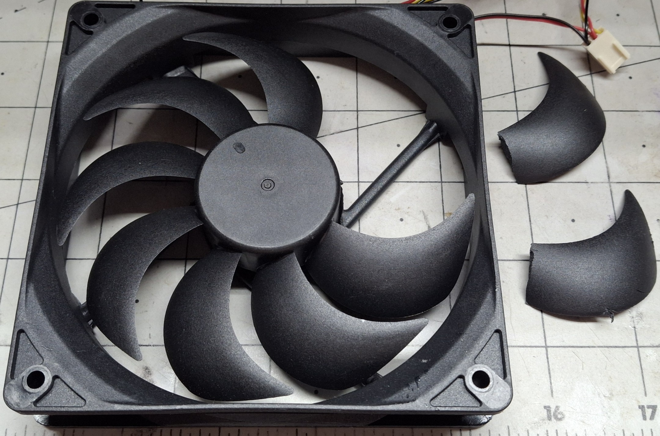
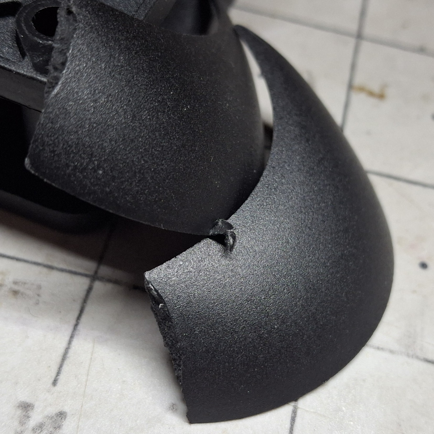
Speaking of broken into pieces, I about sliced my finger off, breaking a couple blades off the new computer fan I just installed in the old computer in the process! Ouch! Those puppies are SHARP! Well now I have a deep slice in my fingertip, bleeding everywhere, and a new fan that needs replaced. Again.

Things went from a periodic bearing growl from the old fan to increased volume from the increased airflow of the new fan to shake, rattle, and roll from the imbalance of missing blades! I was in the process of looking for the model number of the power supply fan and reached in the open case to lift it without thinking these things were dangerous.

I don’t know how many times in the past I’ve stopped a cooling fan with just my fingers without a thought of getting injured. These things aren’t generally that powerful and it doesn’t take much to stall the motor. Not these new ones! They run faster, with more torque, and knife edged blades. Talk about a recipe for disaster! Lesson learned.

Oops. Missing Blades.
Sharp Blades Cut Into Each Other. And Me.

Rats! Again!

I hadn’t seen any rats for weeks after the initial culling, but tonight they’re back for a reprise, what looks like the remaining half dozen I failed to kill the first time around. But this time I’m seeing smaller ones too, like the size of mice. Even worse, I’m seeing mating action to make even more of the little bastards!

I still have a number of traps strategically placed under the corners of the deck where the rats like to scurry up into the slots in the concrete post bases on either side. But even though they’ve been tripped and reset time and time again, still nothing in them! I thought maybe we’d scared them off. Nope. Need a better mouse trap…

Nick had sent me a Facebook link to some contraption on a Facebook group as a starting point, but of course you have sign up for the group and a wait for a moderator to add you. I don’t mind that as much as jumping through their hoops and answering their 20 questions only to be ignored. Fuck them. Didn’t really want to join their fucking group anyway.

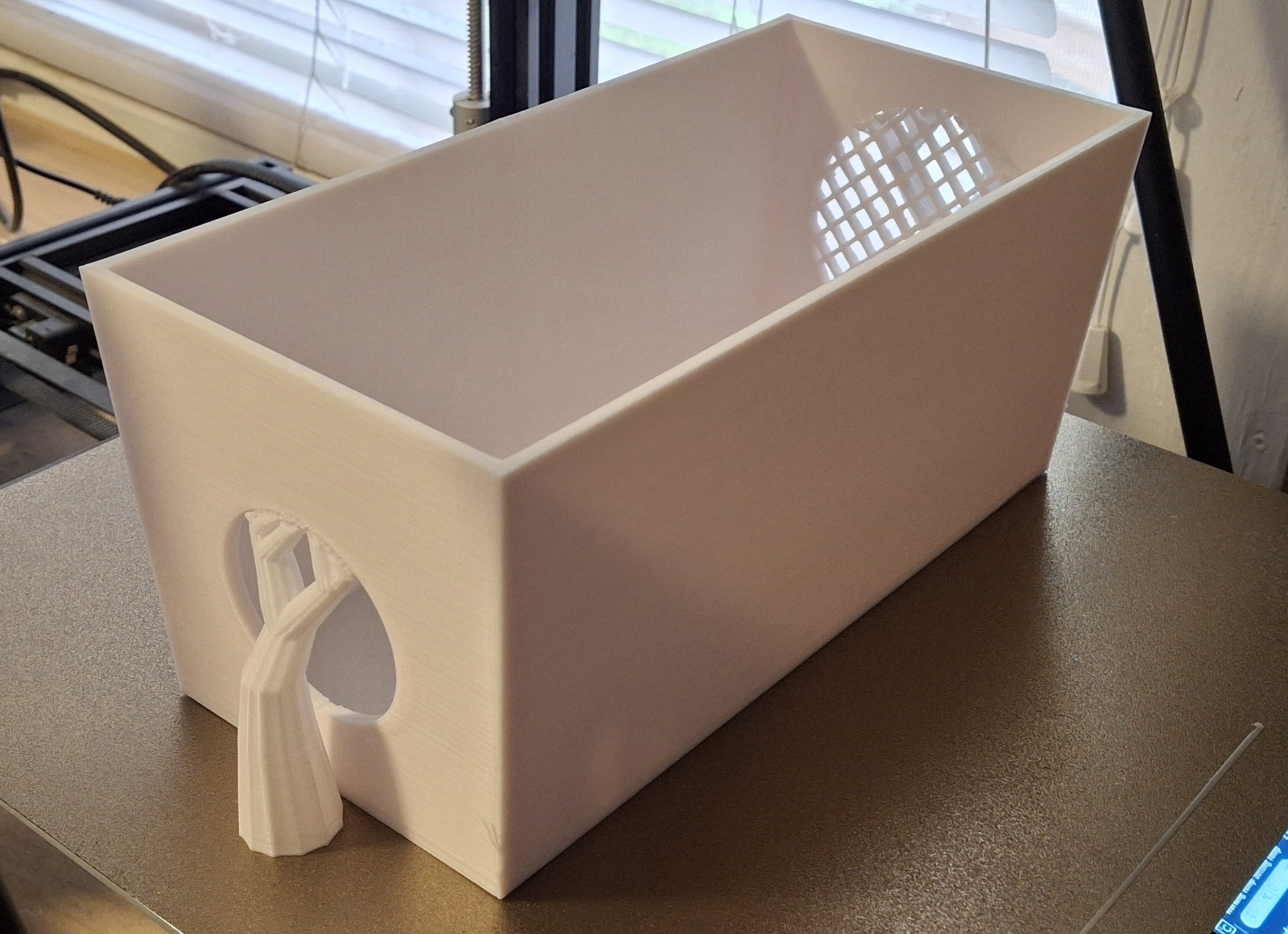
The gist of it is an ammo container from Horrible Freight, modified with two holes cut in either end. The idea is to place yummy food just the other side of a larger opening with a hardware cloth mesh blocking access to the enticing bait just the other side of it, forcing them to the other end which leads to the trigger of a trap just inside it.

Death Trap
Death Trap

Death Trap

My first thought is for all the time and effort to make the modifications to a bunch of these ammo boxes, the time is better spent designing a 3D printed solution that’s ready to use hot off the build plate. Time to switch gears from the switch casting design and focus on a new, more deadly approach. We’ll call it “Death Trap”.

I have the proof of concept prototype printed within a day. The second generation versions are geared toward chamfered edges and glue in mesh pieces. Printing the mesh in place added hours to the print time, so the second gen uses a separate mesh that takes maybe 20 minutes to print and glue in place.

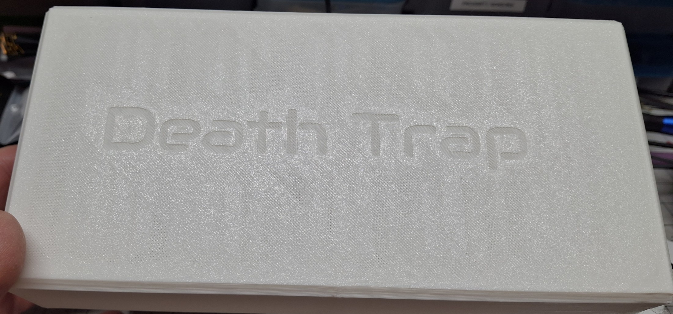
I even added an embossed “Death Trap” moniker to the cover. But even with the gen 2 mods, the box takes ~12 hours to print and the top another ~8 hours. Basically a day per Death Trap. Even worse, there isn’t enough filament on a single spool to print two entire Death Traps! There’s roughly 330 meters of filament on a 1Kg spool, a little over 360 yards.

If the figures are to be believed, the top takes 71.46 meters and the box another 107.56 meters. Doing the math, that’s 78.13 and 117.53 yards, respectively. In any case, twice that is more than 330 meters, at a little over 358 meters. I just bought four spools of white and I’m already down to one after printing four Death Traps!

Prototype Death Trap Base With "Tree" Supports
Prototype Death Trap Base With “Tree” Supports

Double Trouble or Death Trap Jr.?

At first I tried simply halving the rat sized version into a mouse sized version, but it ended up being slightly too small. Another hastily designed prototype hot off the presses, er, printer, lead to a second generation with the same features as the rat sized version, i.e. beveled edges and glued in mesh. Even a top with the embossed “Death Trap” logo.

So now both printers are hard at work printing Death Traps, the new one the large rat sized version and the old one the mouse size versions. But half sized means one eighth the print volume, so the mouse sized versions take only a few hours each. For comparison, the top takes only 18.61 meters and the base just 22.93 meters.

The Death Traps are specifically designed around the dimensions of the Victor M035 Mouse and M205 Rat traps. I originally printed the mouse versions in black, but it appears just the heat from sunlight is enough to deform them. New ones in white are coming soon.

So far, they’ve caught zero rats or mice. Sadly, I did managed to snap a squirrel though. No more leaving them set them during the day. In the past we may have gutted and dressed out that squirrel for a meal, but these Florida squirrels are tiny compared to the ones I grew up with in Ohio. He’s on his way to the dump or incinerator with the trash pickup.

Taking The Win(s)

While I may not have caught all the rats, at least i caught half of them. Still wondering where they came from and why such a large number of them? At this point I’m taking the win. From the research I’ve done, rats are leery of something new to the environment, so it may take some time after introducing the Death Trap for them to get acclimated. Time will tell.

Another win I’m taking is the week off for July 4th along with both the weekends surrounding it. Well, at least the weekend before. The Saturday of the weekend after was helping the kids move most of their stuff to their new digs. But that was the only big interruption of progress.

The biggest recent win for me by far is getting the old Tevo Tarantula Pro 3D printer back online and cranking out the prints. When I bought the new, bigger one to replace it, it promised to be faster, but the old one continues to run circles around it. I thought I pushed it to its limits before, but accidentally set it to slice even faster and it still keeps printing!

Fixing The Floor (Again)

I was finally able to get the plywood floor of the office sliced in half and properly supported. Because the actual office floorboards are the original porch decking, they slope toward the back wall at ¼” per foot, for a total drop of 2″ over the nearly 8′ width. I placed a 4’x8′ sheet of ¾” plywood over it, supported in the middle by 1×4 and a 2×4 at the back edge.

Since the porch porch has settled of the century the house has been here, and continues to settle, I overcompensated a bit, just in case. The first 2′ of the 4′ width of the plywood sheet is raised ¾” by the 1×4 and the remaining 2′ another ¾” for a total of 1½” by the 2×4.

The problem was both supports shifted away from where they originally started out and the plywood became “spongy” and “bouncy” and anything sitting on the plywood bounced right along with it. I didn’t dare stack anything for fear of it toppling over when I walked on it.

Nick gave me his battery powered circular saw that made quick work of it. That is, once I had everything off the plywood, the carpet pulled back, and the centerline measured and marked. Why cut it in half you ask?

Better Than Ever

Because it’s much easier to lift out half that sheet of plywood, leaving the desk and computers in place, then place the supports where they belong and fasten everything together. With that done and the carpet back in place, now it’s solid as a rock, just like I wanted it to begin with. Better than ever!

Now I want to extend the areas under my desk and off the end under the work cell so everything is at the same height. It’s bothersome having the ¾” plywood just end where my feet hit the floor under my desk, with a similar situation under the work cell. But that’s a problem for future me as they say.

We cleaned out my closet, and the only thing I kept was a single polo shirt and my motorcycle boots. Everything else is gone. And with that, I’m going back to getting things done. Time to start making room for all my HO scale stuff still sitting in the corner room over at the other house. And styrene model kits. And file cabinet. And… You get the idea.

Making Room

I accomplished a lot of the things on my list, not as much as I wanted to get done, but I never do. Making room for the most recent acquisitions in the closet was a big goal for me over my time off, and I managed to get most everything stuffed in the closet, but there’s still more to be done there.

The idea is to make room for all my bins, currently sitting on top the file cabinets, over on the cabinet at the foot of my bed where all those recent acquisitions used to sit. Mission almost accomplished. But now I need lights in the closet to see what I’m doing.

I had to take time away from that task to look into it. To that end, I feel another Lighting project coming on… I’ll spare you the details and save them for another post. When I put in the new closets, it was long past when we rewired the house, and before I tore them out the originals didn’t have electricity run to them either. Battery power it is.

Stay tuned for more updates on that and the progress of moving what’s left of my HO scale empire from the other house out here. I feel a bookshelf layout coming on… Nope. Not until we’re able to run train the the Barkyard again!


It’s Alive! 3D Printer Resuscitation

It’s official! I finally managed to get that old Tevo Tarantula Pro (TTP) 3D printer back online. It’s been sitting on the shelf with the new printer for over a year now, useless and just taking up space. With even more recent acquisitions, space is at a premium. I’m to the point where if I can’t get it working, it has to go to reclaim the wasted space.

Thankfully it didn’t come to that. But I was ready to start parting out the old TTP, either to use for other projects or to sell online. If you’ve read this post about its demise, you know it’s been the mainstay of much of our Barkyard “imagineering”. It left us in the lurch when it bit the dust.

The new Sunlu S9+ printer has been a steady source of new prints and inspiration, and continues to pump ’em out, so it’s not like we need another 3D printer. But… We already have one and it sure would be nice if it worked. Spoilers. It does work. As well as it ever did. In fact, it still has that damned offset to the right and the top that I remember!

Hot Off The Presses… er, Build Plate

So What’s The Problem?

Essentially the problem is me. At least the reason it hasn’t been fixed until now is my fault. The original problem was the wires flexing enough that the hot end heater circuit became intermittent, causing a massive clog the hot end just couldn’t recover from. Mainly because I broke everything trying to get it apart.

The reason I say the problem is me is because it took me so long to finally get fed up with the situation and finally do something to resolve it. I tried to put everything together after ordering and receiving a new hot end, back when it first failed, but was never able to get it to reliably PID tune the nozzle heating.

If that sounds like gibberish, it means that any heating related elements need to be “tuned” to function properly, without going into “thermal runaway”, a condition where the temperature continues to rise out of control. The last thing we need is a “fire starter” in the house. We’ll get back to PID tuning in a bit.

Totally Irreparable Hot End

An Incorrect Assumption

At the time, I thought the replacement’s use of inline connectors was causing too much noise for the electronics to deal with and put it aside for later. Later never came. All that needed done was to remove the those connectors and solder the leads together as one solid connection from the heater and thermistor back to the controller.

It was never a high enough priority to choose to take the time to do that. If you’ve ever taken apart the print head of a 3D printer, you’ll understand the dread of doing so. It never goes back together the same way it was before taking it apart. And it never goes together correctly the first time. Or the second. Or the third. You get the idea.

Another problem is where to work on it. Once it’s torn apart, everything has to go back together, working or not. Since I share my workspace with my work computer during the week, I’d have to move it out of the way come morning. That doesn’t leave much time to get things done at all. Starting after supper and working until midnight, maybe 6 hours.

Heavily Damaged Hot End Fan Shrouds

Where Did I Leave Off?

I decided Monday evening to try to figure out where I’d left off way back when, tearing into it after supper. First I had to sift through the “tin” of 3D printer parts. It was an opportunity to sort things together that share a common use, like bowden tube and the related push connectors, and refresh my memory of what all was in there.

I found both the old and new thermistors along with the old heating element. I don’t plan on using it since the new one’s already in place. Using the old one would require taking the heat break and hot end back apart again just to swap them. The idea is to just remove the connectors and solder the wires together.

Next is taking the print head apart. There are several parts that come together to make a complete print head. The main assembly that “contains” everything is the fan shroud with three separate cooling fans, one dedicated to the heat break, essentially a heat sink with fins that it screws to directly. The two others on either side to provide work cooling.

The heat break has a cooling fan so it doesn’t melt the end of the bowden tube or the filament. It’s meant to provide a path to guide the filament to the hot end and nozzle. The hot end, with its heater, thermistor, and nozzle fits into the bottom of the heat break. The hot end is where the solid filament is turned into molten, oozing plastic, and forced out the nozzle.

Heat Break and Hot End Relative to Print Head Fan Shroud

Making Quick Work Of It

Because the hot end parts use connectors, it’s easy to disconnect them and move them out of the way. The connectors are snipped free and the wires stripped in preparation for soldering. Turns out the thermistor that came with the replacement hot end is the wrong one! Well, let’s just say it wasn’t the one the firmware was expecting.

In general, the type of thermistor and its characteristics are “baked” into the firmware when it’s built, at “compile time” as they say. There’s no way to change it once it’s built and loaded onto the controller short of changing it, rebuilding it, and reloading the new version. When I first got it, Nick was the one who built the firmware. Not sure where the source code is now…

After much searching on the interwebs, I found a WordPress page dedicated to the TTP, and true replacement thermistors meant for it listed there. I ordered a set of ten, just in case the original is bad. They’re also replacements for one of Nick’s printers as well. They come with a 1 meter pigtail, so my thought is I’ll just dress one into the harness.

Old Thermistor, Far Left, Out of Focus and New Heating Element Wiring, Center

Change Of Plan

Doing anything with the harness looks like it would be a nightmare. Change of plan. I’ll just use the old thermistor. After all, as far as I know there was nothing wrong with it. I just snipped it out of the circuit back then when I found the predrilled hole for it in the replacement hot end was bigger than the original.

After some fiddling with it and the old hot end I discovered that predrilled hole in the original was deeper than the thermistor was inserted, as if it was meant to rely on the heat being radiated and not conducted through direct contact with it. There was no thermal paste or any other means of conducting the heat from the metal of the hot end to the thermistor.

Thankfully getting the old thermistor in place is as simple as inserting it into the predrilled hole and clamping it in place with the original screw and washer. Soldering the wires back together takes some “fixturing”, but with the help of the “third hand”, I made quick work of it. I even remembered to put the heat shrink on the wires before soldering them!

New Heating Element Wires Won’t Accept Solder?

Make That Change Of Plans

Happy with the relative ease of restoring the old thermistor to the circuit, it’s time to tackle the heating element. Now I know why the thermistor was easy… Because the heating element is refusing to cooperate. Not so much the element itself as the wires connected to it. There’s no amount of flux or heat that will allow the solder to “wet” them!

Now I know why they had connectors! Not sure if it’s aluminum or steel wire, but you can’t get solder to sweat onto either of them. I’ll never understand why any electronics manufacturer would use anything but copper wire. How much money did they save? Those connectors, crimp terminals, and assembly had to cost more than copper.

When I saw the silver color of the wire, I just assumed they were tinned copper. Wrong! As much as I wanted to avoid taking the hot end apart, looks like I’ll have to now. There’s no other way to gain access to the heating element. And just as I feared, I stripped one of the tiny 3mm grub screws in the process!

Print Head Assembled and Wires Neatly Dressed

What’s In The Big Prize Stash?

Of all the small, metric hardware we have, grub screws aren’t in the inventory. Then I remember Nick gave me one of his old hot ends from a different printer. Maybe it has one? Score! It’s a smidge longer, but it should work. Problem solved. Time to solder the old heating element in place.

The red, braided cover is more difficult to “strip”, but the flush cutters manage to cut it back far enough to strip the actual insulation. Lighting strikes twice as I remember to install the heat shrink before soldering again! Time to shrink things in place with the battery powered heat gun.

After struggling with getting the new heating unit out and installing the old one in its place, it’s time to put things back together. That’s easier said than done, but a LOT more than I thought would get done in one evening! It only takes three tries to get everything back together and ready to test!

Giving The Hot End “The Boot”

Third Time’s A Charm?

The first try is a bust when I realize the hot end interferes with one of the work cooling fans in the shroud. Let’s loosen and strip those grub screws some more! The next try is because I didn’t have the thermistor clamped down enough and it just pulled out. Let’s loosen and strip those grub screws even more! Third time better be the charm!

By now I’m using the small needle nose pliers to “cinch” down those grub screws that last little bit. I didn’t realize it at the time, but the nozzle on one of those work cooling fans was cracked and falling to pieces. I zip tie what’s left of it together enough to get the screws in place. Until it cracks and one of the screws falls out!

The other nozzle was totally deformed into a crescent moon shape, pretty much pinching it off. A little work with the heat gun and a screwdriver opens it back up, albeit haphazardly and crooked. I searched for replacements online, but don’t know what those things are called. It will be good enough to test with and at least they’re accessible.

Ready For Initial PID Tune and Testing

The Big Test

Getting everything connected and plugged in and turned on is a big step toward testing the repair, but first things first. Time to do a PID tune on the nozzle heater. This is where the hot end replacement failed the first time around. Had I known then what I know now, this thing would have been working a lot sooner.

So what the Hell is a PID tune? PID is short for Proportional, Integral, Derivative. It’s actually the parameters were tuning for the heating control system. Proportional is exactly what is sounds like, a proportional response to the heater given feedback from the thermistor.

The Integral part is like a long term averaging, so as not to overreact. Derivative is more responsive to the rate of change of the thermistor feedback, the faster the change, the faster it responds. The three taken together allow for a fast response to a given input, without overshooting the value, with small excursions around the setpoint.

Amazing First Time Nozzle Temperature Curve

Absolutely Amazing

It’s incredible how close the thermal response is to ideal the first time through tuning! It’s like this thing was never offline. Without going into too much more detail, many 3D printers use Marlin as the base source code for building the printer’s firmware. The printer is commanded using GCode and Marlin (“M”) commands.

For example, to start the PID tune process, an “M303” command is issued. It takes parameters, like which heating element to tune, what target temperature to use, and how many cycles to run before completion. In our case we’re tuning the nozzle heater, so the command would be: “M303 E0 S210 C10”.

The end result is a new set of parameters to replace the existing parameters with. This should be done any time the nozzle assembly is modified to account for any variations or changes in the heating characteristics. In our case, this becomes: “M301 P40.10 I5.44 D73.92”, where P is the Proportional value, I is the Integral value, and D the derivative value.

The Moment Of Truth

One last thing to do, extrude some filament and verify the nozzle is heating as expected and no thermal runaway occurs. I set the controls to extrude 50mm and it’s looking good! I command another 50mm and… Schmidt! It’s extruding alright, AND PUSHING THE HOT END OUT RIGHT ALONG WITH THE FILAMENT!!!

That’s all she wrote for tonight. The printer is on the shelf and out of the way for work tomorrow. I’m not taking it all back apart tonight. Without new grub screws to replace the stripped out ones, it wouldn’t make any difference anyway. There’s no way to fix this until the grub screw assortment I ordered gets here Wednesday.

Still, it’s very encouraging that everything else is working. None of those problems from the first time around. If there’s a lessons learned from all of this, it’s don’t trust it when they say it’s compatible with your particular brand. It’s not. Another is hex keys and screws are easily stripped with excessive force, especially when they’re small.

A Two Day Wait Just For Two Set Screws

The Suspense Is Killing Me

I hope it lasts… But seriously, the wait for the grub screw assortment to arrive is torture, not knowing if this is really going to fix the printer. It arrived early in the afternoon, so I was able to get right to it once I was done with work for the day. I’ve had this thing apart so many times now I could do it blindfolded. Not that I’d want to mind you.

No way to know if pushing the hot end out caused any other issues until it comes apart. A close inspection reveals everything is clean. For whatever reason it’s giving me fits trying to get that hot end back into the heat break, but in the struggle, I realize the “flat” on the hot end connector appears in one of the grub screw holes. Hmmm…

I wonder if that’s what caused the loose fit? If that flat isn’t close to perpendicular to the grub screw, it may seem tight, but won’t be. Because it threads into the hot end, it’s at a slight angle when the hot end is square to the heat break. This time it gets aligned with the flat and the grub screw tightened down along with the other one.

Drum Roll Please

This print head has been apart and back together so many times, the bowden tube is fighting me now. The way the push in connectors work is they “bite” into the outside of the tube using some type of one way clutch to allow inserting the tube but preventing it from being pushed back out. Only depressing the release ring will allow it to push back out.

Over time, the repeated insertions leave a permanent “ridges” that refuse to push back through that clutch. The only way to fix it is to replace the bowden tube, which is exactly what I did. The connector threads into the top of the heat break and holds the end of the tube tight against the top of the hot end so no molten plastic can leak out.

The old one was a bit short anyway, so now’s a good time to replace it. Filled with new confidence, it’s time to test this latest incarnation. First a PID tune, then the extrusion test. It works! The hot end stays put and I can repeatedly extrude filament! No movement of the hot end whatsoever! SUCCESS!!!

Back To Basics

The next hurdle is to adjust the Z offset, that is to say the offset from when the BLTouch sensor detects the build plate and the nozzle contacts it. This has always been a hassle and a long term struggle to properly adjust that distance. Whether the first layer adheres to the build plate or not hangs in the balance.

Too much and the nozzle crashes into the build plate. Not enough and the first layer just sticks to the nozzle and not the build plate. Somewhere in between is the balance where prints just stick or they don’t. It’s a painful process of cancelled prints and minute adjustments and more test prints.

Until this time. I actually found an article online on how to precisely measure this offset in one operation. Without going into too much detail, the secret is to turn off the “soft limits” that stop the head travel before actually reaching the desired adjustment. That’s the piece of information I’d been missing this whole time.

Probably The Best Test Cube From This Printer So Far!

The Old Standby

With the Z offset within a couple hundredths of a millimeter, it’s time for a test print to see if the printer really works. The good old 20mm calibration cube is the best choice. I don’t want to have to reslice it right now, plus I know it’s worked on this printer in the past, and it only takes 25 minutes or so. Off we go.

I’d forgotten how much louder the stepper motors are on this printer. Definitely spoiled by the silent stepper drivers on the new printer. Not sure what’s different this time around, but it’s the best test cube I’ve ever seen this printer print! No elephant’s foot. No layer shift. None of the artifacts I seem to remember in the past.

I AM ECSTATIC! This is beyond awesome. This is beyond belief. I cannot believe the old printer is back online and working as well as it ever did! I cannot believe I did not do this this sooner! It’s May of 2025 and the printer failed February of 2024. Considering this all came together in a couple evenings, I should have made the time long ago!

A Few More Tweaks

I planned on getting to this point a long time ago. I even bought a second Raspberry PI 4 to control it. It just sat there this whole time, unused and ignored. Thankfully it was already configured and ready to go when I needed it. There’s only one thing that still needs some work. The PI cam. It’s oriented in the portrait mode.

Recently I figured out how to tie into the camera stream using the browser and VLC. So I was a little confused when the Octoprint version was correct yet portrait mode but the streamed version was rotated 90°! A little more digging and I figured out how I managed that.

There’s a setting in OctoPrint for “Classic Webcam” that allows flipping both horizontally and vertically and well as rotating by 90°. Now they’re both rotated 90° and portrait mode! Then I realized the PI 4 controller for the new printer is standing vertically compared to the old one that’s still horizontal and it dawns on me it’s the internal camera mount.

OctoPrint Camera Settings for Stream, Snapshot, and Time Lapse

More Tweaks

The see through case for the PI 4 only has two mounting holes, not four. The problem with that is if the orientation is wrong, i.e. portrait mode in this case, then the only other option will still be portrait. The case itself must be rotated the extra 90°. I designed a new mount for the case back then, but only printed one because that’s all I needed at the time.

So that’s the first real print job for the printer, printing its own vertical PI 4 case mount. I used the original sliced version, but soon regret that choice once I remember the problems it had printing the first time. Not only did it have a brim that didn’t stick to the build plate, the small hole features also cause headaches.

Those small features invariably end up sticking to the nozzle and not the build plate, which ends up grabbing other parts of the print and ripping them free from the build plate, dragging the whole mess along until finally cancelling the print. In this case, it’s something even more stupid, the filament “jammed” on the spool and caused it to stop extruding!

After spooling out nearly 10 meters (~33 feet) of filament, I finally manage to untangle the snag on the supposed “non tangle spool”. It’s hard to describe, but once the tension is released from the filament, an entire layer springs loose and somehow the other wraps manage to overlay the loose end. This traps it beneath them once tension is restored.

Unfortunately, the more tension, the tighter it pulls down over the end being fed to the extruder. May as well tie it in a knot at that point. The extruder actually pulled the spool off the counter, filament dryer and all! The extruder drive gear nearly ground through the filament when it stopped spooling out.

With the rewound spool in place, I extrude 200mm of filament, 50mm at a time, to ensure it didn’t cause a clogged nozzle or other issues with the extruder. Not sure why this particular spool of white PLA is so snag prone, but it’s jammed twice now, once for the new printer and now once for the old one.

Even More Tweaks

Back to the drawing board, or in this case, SketchUp. Once I finally found the original design on disk, I made a quick change to put down a solid first layer, then draw the small features on top of that. If the first layer isn’t sticking, there are other issue that need addressed. But this trick has worked for me on other designs, e.g. Run In Stands.

The nice thing about new STL is I can slice without the brim. In fact, I don’t even need a skirt! Another trick I learned from the new printer is how to add enough of a “primer line” to the startup GCode for every print. Essentially it moves to the edge of the build plate and extrudes two thin lines, side by side, enough to ensure the nozzle is flowing.

The skirt accomplishes the same task, but sometimes doesn’t stick and causes more problems than it solves. Those primer lines are just enough to gets things started. The next print is a success, but I realize that the nozzle temperature in the slicer was still set to 200°, not 210°. It’s not going to hurt this print, but I fixed it for next time.

Next steps are to glue the freshly printed PI 4 mount parts together and replace the existing mount with the new one. I’ve described the process in detail elsewhere, but the short version is I use a liquid acrylic solvent to “weld” the PLA parts together, similar to styrene cement for building plastic model kits or PVC cement for plastic plumbing pipe.

In similar fashion, the best strength is obtained obtained in 24 hours, so I let the new mount assembly set up overnight then swapped it out with the old one the next morning. I had forgotten how much I detest those mini tripods I bought all those years ago. At the time, I thought they’d be useful for my job, but they didn’t work out.

Instead they ended up here at home and holding up the PI 4 controllers for both the 3D printers. They’re study enough, with telescopic legs to adjust to unlevel surfaces, but the ball “joint” that allows the camera mount to swivel is way too loose. No matter how hard I cinch down on the set screw’s stupid little plastic handle, it ALWAYS ends up loose again!

The PI 4 Case on the New Mount on the Annoying Tripod

The Final Tweaks

Guess I should stop complaining about it since it only matters when I tell OctoPrint to capture a time lapse of a print. Even then unless I fabricate some overly complicated “Extendo Mount” contraption to hold it further away and higher off the build plate, the capture is too close. The PI camera for the new printer is an 8MP version, but the setup could be better.

The PI camera for the old printer is an older 5MP version that has problems with low light. Even with the bright office light in the ceiling fan on, the time lapse still looks dark. There may be some other settings I can adjust in the Linux OS itself, but since I don’t usually capture a time lapse anyway, what’s the point?

The last thing I want to figure out is why prints on the old printer are ALWAYS offset from the origin, the front left corner of the build plate. I would usually take this into account when slicing, but it’s not an exact science. When I was printing the “Glow In The Day” clocks, they were sized to require nearly the entire build plate and nearly impossible to adjust.

The Offending Setting Causing Those Blasted Offsets

Even more Googling reveals it’s the Cura slicer and not baked in offsets in the printer’s Marlin firmware. In fact, I tracked it down to the actual settings file Cura uses when it wouldn’t let me update the offset values. Turns out they’re not actually “offsets” at all, but rather print head dimensions to the corners measured from the nozzle.

The default print strategy is to print the first layer of copy 1, then first layer of copy 2, then second layer of copy 1, then second layer of copy 2. The sole reason for those settings to exist is to allow printing multiple copies of the same print to finish sequentially, i.e. completely print all layers of copy 1 then completely print all layers of copy 2.

Unfortunately, when  the “Apply Extruder offsets to GCode” is checked, the slicer automatically adds those printhead offsets to the actual GCode values when slicing. This is so the printhead can avoid collisions with the other print(s).  Not sure where to tell it to print each copy sequentially, but I don’t plan to use the feature anytime in the near future either.

To be sure I re-sliced the test cube and moved it as close to the front left corner as possible. Both the slicer and OctoPrint appear to have built in safeguards to avoid printing outside the edges of the build plate. Looking at the GCode it leaves us about 5mm away in both X and Y. The closest I can get is 1.999 x 1.999 away from the origin (0, 0).

Finally Figured Out How To Get Rid of That Blasted Print Offset!

The Final Tests

A quick test print of the re-sliced calibration cube shows it’s right there at the front corner. It also clearly shows the slicer settings leave a lot to be desired compared to those used to slice the earlier near perfect print. In the Cura slicer there are really too many settings to display all at once, but there’s a way to select which settings are visible.

I need to figure out what those settings were that used to visible to fix that extra buildup of plastic at the corners and the ridges where the infill meets the walls. Also looks like there was some under extrusion on that top layer. This cube looks terrible compared to that first blue one. Another possibility is this is a different filament.

Those tweaks will have to wait until after the real final test print though. Printing the PI mount was a good test, albeit a short one at just shy of an hour, but the true test is the one that takes 6 hours or more. For that we’re printing the last eight run in stands I need for the Mikado’s tender.

That calls for a new slice since the standard one I use has only six and takes more than 5½ hours on the new printer. Had to laugh when the slicer told me 4 hours! The curious thing is it took about the same amount of time to print eight of them on the old printer as it did six on the new one. Ironically, the new one is supposedly faster than the old one.

Printing The Run In Stands

There must be another hidden setting I’m neglecting because all the print speed settings are the same between the two printers. I did notice it seems like the old printer is moving faster than the new printer using the same slicer settings. Guess it’s time to push the new one to its limits just to see when prints start to fail. Maybe an overall acceleration limit?

That’s a problem for future me as they say. For now, I’m thoroughly pleased with the performance of the old printer. It’s everything it used to be and nothing unexpected. I take that back. I did run into something unexpected when trying to narrow down those offsets. The X and Y range is supposed to be 240mm, but the Y axis hits mechanical limits at 230mm?

Unexpected Discoveries

I remember when Nick and I originally put this together we had to move the Y limit switch just past the end of the one mounting screw to where is was just holding on. Maybe that center rail the print bed rides on needs adjusted away from the front panel? There may be another 10mm to be had. Hopefully there’s an extra 10mm in the timing belt too.

The X axis looks like it could go on forever. Well, at least until it reaches its mechanical limits, well past 250mm anyway. The limiting factor at this point is the flexible metal build plate, limiting the build area to about 232mm, maybe 233mm, in both directions.

I tested the Z limit of 260mm as well, but both the harness and bowden tube to the print head contact the top crossmember well before that, before 240mm anyway. I doubt I’ll ever be printing anything that tall, but if I do, that’s what the new printer is for. Its build volume is 310mm x 310mm x 400mm.

For now it’s working, and working as well as it ever did. Considering the limits of the build plate, I’m not going to take things apart just to get that last 10mm out of the Y axis when it’s more like 2mm-3mm to be had. I’ll use the big printer. It’s quicker and easier. Well, it will be quicker once I figure out the slicer settings!

Thanks for tagging along and stay tuned for the next adventure.


Latest Acquisitions – Part II

It had been nearly a year since we added to our equipment roster, until our recent addition of a Mikado, described in our first installment. This time around, it’s an Aristocraft Pacific. It’s as good a deal as could be found. Not as good as the Mikado, but close. It’s a little more expensive and a little less impressive, but only because it’s the early version with plastic side rods and such.

It does have the original sound system in the tender, and it still works. It’s missing the whistle and the bell, but the bell harp is still there. It does have the “cow catcher”, unlike the Mikado. The one big feature it sports is it’s in the B&O Royal Blue livery. And like its ten wheeler predecessor, it’s a bit on the wobbly and unreliable side. But there’s hope for it. It should be fine after a much needed tune up.

Being the early version, it still has the “glowing firebox” feature, no longer present on the more recent Mikado. Best I can tell, the Pacific is pre 2003 and the Mikado 2003 or later. The difference is the Mikado has an added Battery vs. Track Power switch stacked with the Motor On/Off switch in place of the glowing firebox door in the Pacific.

The Pacific has Motor On/Off on the cab floor, along with the Lighting On/Off switch, also on the floor of the Mikado. The Pacific placed the Smoke On/Off switch at the front of the engine on the pilot frame. The Mikado has its Smoke On/Off switch on the cab floor, opposite the Lighting switch.

B&O Royal Blue Pacific

Initial Findings

I did manage to find the manual and more information on various large scale sites. It appears to match the “Old Pacific” manual. And now my searches are turning up the ART-5400 PWM controller for use with it. Still haven’t found the “magic words” for the search to find the waveforms. But then again, that was probably a closely guarded bit of secret information (read intellectual property) when they were still in business.

I won’t go into all the details of our foray into PWM motor controllers here. It’s pretty much covered elsewhere. The long and short of PWM, for me anyway, is the annoying buzz at anything in the audible frequency range, and the lack of response from any built in constant lighting circuitry at any frequency greater than a few kilohertz.

Considering this locomotive also sports its own track powered sound system, not sure how Aristocraft managed to get the PWM concept to work, let alone together with it. It does require a fair amount of voltage before anything works. IIRC, the wheels didn’t even start turning until around 8V.

Original Aristocraft Sound Card

We Have Sound

It took some doing to figure out how this sound board works. When I first opened the hatch on the tender looking for a battery, not only did I not find one, I didn’t even see the 9V battery clip laying inside there on the very bottom. It became very apparent when I removed the tender shell to get a look at what was going on inside.

At first glance I can tell this is old technology, likely from the ’90s judging by all the discrete components surrounding four Dual Inline Package (DIP) style integrated circuits. One’s a quad comparator op amp, one’s a decade (÷10) counter, another’s a hex inverter/buffer, and finally a dual channel audio amplifier. I finally got rid of most of my DIP style parts recently, deciding I’d never be using parts that were at least 30 years old in any design.

Of course the first thing I have to do is look up which post is which on a 9V battery so I can attach the bench supply with the correct polarity. Let’s try not to let out the magic smoke, shall we? So with that knowledge in hand, I power on the bench supply and… Nothing. Adjusting the voltage has no effect. Neither does adjusting the current limit. What about spinning the wheel with the sensor on it? Nothing.

Or Do We?

All this is going on while trying to record a video of it, and paying more attention to that, the lead that fell off the bench supply goes unnoticed at first. Not sure what the first clue was, no current draw perhaps? With the power now connected, the faint sound from the speaker of amplified noise together with one of those old style analog bell resonator circuits, right on the edge of ringing, riding on top of the noise can be heard.

Adjusting the volume knob has the expected “crackle”, another remnant from analog days where any DC voltage present on the adjuster arm detects every speck of dust in its path and creates a loud “pop” in the speaker when it finds it. But the real payoff comes from spinning the wheel with the sensor on it. The bell comes to life, then the chuff, chuff as the wheel spins faster.

It does manage to make reasonable bell, chuff, and hiss sounds, but will be replaced once the I2S sound sketch is up and running. The short exposure to that Phoenix 2K2 card spoiled me. It’s less than half the size of this thing, makes much better sound, and can be controlled simply by connecting external reed switches or programmatically via DCC or other means. And even that one’s obsolete!


Does It Run?

Jumped the gun describing the sound system first though. Once the tender’s open, it’s obvious more research is required. Testing out the engine came first. I set it on a short stretch of track and connected the test leads from the bench supply. It does run, if only for a short time before it runs off the end of the track. Reversing the polarity sends it the other direction.

So it does run, but how well is unknown until the first set of run in stands is finished printing and assembled. It takes six for just the three driver axles. Those together with the other ones I already had printed and assembled should be just enough… If the mix matched colors isn’t an issue. That set took all but the last one of the roller skate bearings. Time to restock those and the other hardware.

It probably wouldn’t have taken as long if the assembly steps hadn’t been recorded as well, but at least they’re finished. Once on the run in stand, it’s obvious this has a lot of slop designed in, most likely for tight radius curves. There’s at least a quarter of an inch (~6mm) slop side to side in each of the driver axles. Couple that with the middle axle being driven only by the plastic side rods and it’s a wobbly ride!


Death Wobble?

Don’t know if it’s “death wobble”, but she’s certainly a rockin’ back and forth and side to side! With a slight tug on the cab the wobble is tamed somewhat, but not entirely. While the first and last axles are physically linked together by a shaft to the motor, that middle axle is free to “float” between the side rod links. There are two of them, not one solid single side rod like on the ten wheelers.

One link is connected between the drive pins of the middle and rear drivers. The other connects to the that link and the drive pin of the front driver. The connecting rod from the piston and cylinder shares the middle driver’s pin with one of the side links as well as the arm to the valve rod. The sector arm rocks back and forth around a centered “Johnson bar” with the valve rod action.

That’s the extent of valving action. I’d like to draft up a CNC design to mill out metal side rods and operational valve links with prototypical reverser action. Unfortunately, the Mikado suffers the same valve action limitations with rigid cast plastic in place of the expected moving mechanism. Just now thinking about, it may be possible to borrow valve parts from the ten wheeler replacement mechanisms. Hmmm…

Saving The Best For Last?

More like saving the boring for last. The first installment of this series focused on catching up with where we’re at and why expanding the roster wasn’t a priority. Then it moved on to how most of these historic items are no longer available except for those rare offerings on eBay. The occasional item may pop up in an online dealer’s list of previously owned items, but they’re usually way overpriced.

With that being said, the particulars of the deal were held until the last this time around. This particular acquisition was one of those buy it now or best offer deals on eBay. Most of those available were in the $750 – $1150 “Buy It Now” price range. Not sure what the original price was back when Aristocraft was still in business, but even so, that’s pretty steep.

The offer was half the ask, and the seller countered with an extra $50 tacked on. Combined with tax and shipping it was a little over $500 all told, not quite a hundred dollars more than the Mikado deal, where the tax and shipping together were still less than just the shipping here.

Stupid eBay Tricks

Guess it’s a common “trick” eBay sellers use to avoid having to pay more of a surcharge or lose as much when some buyer tries to rook them, but when I see shipping costs of more than a hundred dollars, it better be hand delivered, straight to my hands, and not tossed around by the postal system until it’s dropped at my doorstep. Literally.

One thing I didn’t cover in the first part was all the offers I got from sellers I hadn’t extended and offer to… Way to scare me off. Folks I’ve never met nor reached out to, already “leaching” out to me. I already think what they’re asking is overpriced to begin with. Those offers only put the price in the ball park of other sellers, before I make any offers. No thanks. I’ll keep looking.

I know what these items are worth to me, regardless of what the sellers think they’re worth. “No lowball offers. I know what I got.” comes to mind. But enough about eBay sellers and tactics. I bought the item I wanted for a price I was willing to pay. Granted, it’s not what I thought I was buying, but it’s a good enough start to know better next time. Who knows? Maybe I’ll design my own CNC version of the mechanism and 3D print the rest.

The Best Part

The best part is all the video material recorded while exploring these “new to us” models. It’s been way too long since we’ve posted any new videos to our YouTube channel. They pretty much stopped when our beloved Brigel crossed the Rainbow Bridge mid 2022. There’s a short of Brigel’s last days with us to mark the anniversary of his passing, but nothing since.

That’s not the only reason, but it definitely took its toll on us. Another source of concern was the aging computer system we use to edit and render the videos. It was a real screamer in its day… A decade ago! Now its age is definitely showing. Nick gave me an older video card he had that was still more powerful than the one I built the system with. That’s helped for a while. But the old girl is tired…

But not retired. That system has roughly 20TB of storage. Some of it SSD, most of it spindle drives. It provides network access to all our collected works, knowledge, and projects. When we lost two of the 2TB drives, meant to be backups of each other, we lost most of our pictures from 2013 and parts of 2014. It was the motivation to pull the trigger on a new machine.

A New Hope

The new system is more than capable of creating videos. There were some hiccups along the way, like when the boot SSD failed, and it could have been bricked for more than two months. And all this just after finally getting everything squared away and ready to go. Seemed like we just couldn’t catch a break. I took the opportunity to rebuild a new boot drive without all the extra fluff included with Windows 11.

Back up and running, all the while waiting on a warranty replacement SSD. At first it was a struggle just to figure out who was on the hook for the warranty. Once that got resolved, things didn’t improve much. Not until I finally convinced someone in support that having a new computer that’s essentially a brick sitting under my desk for the last two months wasn’t the user experience I expected when I bought it.

He sent me a new 2TB boot SSD express! The best part was I got another 2TB replacement SSD a week or so later through the standard warranty channels! So I bought a set of USB drive cases and now have two external 2TB SSD drives for portable storage. The new computer itself was already treated to an upgrade of a second internal drive, a 4TB SSD!

A New Video

With all that being said, it’s time to start putting out the videos again. I managed to collect up all the relevant material in a “starter” project I can “save as” to any new video project, then just remove the content that’s not related. Maybe I should just export all the bins and import just what I need into the new project. Guess I’ll try both ways.

I use DaVinci Resolve for making videos. It’s just the free version, but has plenty of features even so. Microsoft was pushing their latest Clipchamp “freebie”, but it’s barely capable of editing out the unwanted parts just creating a short excerpt video. Guess I’m spoiled. I’m using version DaVinci Resolve 18.6, but they’ve already pushed out the new 19 release.

The short video clips in these new posts were created just for them, saving the full up content for new YouTube postings. All we need now is that “flashy” intro for the channel. Maybe even a trailer to boot. Just need the inspiration…

Much more to come. Stay tuned!


3D Printed Casting Mock Ups – Round Two

This is a short follow up on the original 3D Printed Casting “Mock Ups”. Considering the length of the original post, that’s an understatement. But sometimes it’s necessary to fill in the blanks when progress is low and discouragement is high.

Even though progress has been slow, it’s actually been beneficial in this case. The original design is based on our “fleet” of Bachmann passenger cars, literally dozens and dozens and dozens of them. Some modified with our Passenger Car Lighting systems, some still sporting the original 9V battery twin light bulb version. All of them suffering from flimsy, rubberized plastic handrails.

I wouldn’t mention those handrails except we’re talking about 3D printing. What better replacement for plastic than plastic? Well, metal for one. Brass to be exact, but then we’d need jigs for bending the brass to shape, most likely 3D printed as well.

Steps Barely Clear Capstones

Design “Flaws”

Just like those original handrails that failed the test,  so did our original casting design. Well, at least the mock up did. The first flaw was discovered when first fitting the 10′ diameter curved track section. A redesign doubled the number of segments to better fit the curve. This was discussed in the first installment and it works quite well.

The next “flaw” is genuinely a “new” one, as in there’s not enough clearance for the new USA Trains Heavyweight passenger cars. And before you ask, no, there are not dozens of them. But there is a decade of them. There was a bulk deal on ten of them around Christmas time, so I pulled the trigger, as well as ordering a pair of F7 A-B units for A-B-B-A running.

They’ve been packed away since then, awaiting completion of all these “infrastructure improvements”. After unboxing one of them to test with, it was readily apparent the design was too narrow for these behemoths. The car is longer than the mock up! The wheels just fit on a single curve section though.

The steps and the equipment boxes both will interfere with the platform or the capstones. Back to the drawing board! It took some doing, and some days to do it, but I managed to add a “crude” approximation of the new passenger car to the mock up design.

Steps Interfere With Pillar Capstones

Back To The Drawing Board

The test fit also reveals a flaw in the “track trough”. Not sure where I picked up that fault, but for whatever reason, the track is sitting proud of the platform rather than flush with it. To give an idea of how the prototype fits together, most platforms are slightly higher than the track, by about 4″ (10cm). In scale, that’s roughly 1⁄6″.

I figured giving the equipment that little bit of a height boost would hopefully compensate for any errors made while measuring their dimensions. Looks like I worried about the wrong measurement errors. Add that to the list of things that need fixed.

I’m back and forth with whether to try to forcibly disassemble the mock ups or just print all new pieces. I say try because the chemical solvent I use to cement the plastic pieces literally melts the two together into one part. Printing all new pieces is going to take a lot longer.

Each 4″ x 7″ retaining wall segment takes 4½ hours to print. Two of the pillars that join the wall segments take 3½ hours. An 8″ long track trough takes 5 hours. It should have been obvious when the curved track trough only took 3½ hours to print.

Anyway, these flaws are certainly obvious now. Not to worry though, the entire reason for all these mockups is to find the errors and flaws before they’re cast in stone, er… concrete.

Time Better Spent As Debby Approaches

Time Is Of The Essence

Alright, being overly dramatic, but time certainly is the essence of the conundrum. As in there is not enough of it to get ahead of everything that needs done. So little to do and so much time… Strike that. Reverse it.

Some say if deadlines are not set, they’ll never be met. Tell that to hurricane Debby. Now instead of spending time moving closer to the goal of running trains, it will now be spent preparing for a hurricane.

Retract the SunSetter™ awning. Stash any loose items that will blow away, like lawn chairs and cushions. You get the idea. Now add to that the garage where those items are usually stored is still the disaster it was right after the A/C decided to leak all over everything.

Progress is slow, but progress is progress. The large empty storage bin that used to sit in front of the table saw because there was no place else to put it is now filled with HO scale items that used to occupy a slot on the bookshelves in the office. It will fit beneath the work cell, taking up the wasted space under it.

Next Steps

Immediate steps are hurricane preparation, like dumping the work cart full of dirt at the end of the driveway where it has washed out around the apron and sidewalk, then retract the awning so as not to create a cart full of mud.

Beyond the immediate, back to the drawing board. The track trough and curved section redesign has already begun, old hold temporarily to prepare for Debby. I don’t like leaving the 3D printer sit idle for any length of time, but short of printing more 4″ x 7″ retaining walls, it will have to wait for the new part designs.

The big ticket item is capturing the step by step process for actually creating the station platform from all the separate cast pieces and how to create forms with them for a concrete pour. So far the mockups have captured segments of the final product, but not the process of creating those final products.

The garage needs a few more items completed before it’s ready for casting concrete patch into those retaining wall panels. There’s a stud space or two where the sill plate is totally rotted that could use a new chunk of 2×4 before setting the table saw in front of there.

The new shelves are already installed but need some thought put in to organizing what should go there and what will fit. All the things that haven’t been used and won’t be any time soon were thrown out to make more space.

It continues to evolve, like the wall cabinet for electrical items expanding to occupy two cabinets. Next is going through that cabinet that has all the “might be useful” items for the model railroad, ripe for harvesting more trash that will never be used.

Long Term

Long term is 3D printing with PETG, a more suitable material for use outdoors. Definitely more heat resistant than PLA. Not sure about its UV resilience, but paint can mitigate any shortcomings there.

The first designs will be concerned with ties and insulated split jaw parts. The originals printed in PLA lasted about ten minutes before they started to melt and deform in the Florida heat. Those stainless steel rails get mighty hot in the sun!

Next will be structural items, like window and door frames, “gingerbread” decorations and supports on buildings, etc. The ultimate goal is to create our own switches and turnouts, custom fit to the needs of the Barkyard Railroad.

Stay tuned. Much more to come.


3D Printed Casting “Mock Ups”

I’ve been busy 3D printing lately. So busy I’ve gone through nearly eight 1Kg spools of filament so far. That’s almost twenty pounds of plastic and I’m not finished yet! Why so much? Well, that’s a bit of a story, but I’ll try to keep it brief.

I’ve been struggling with optimizing the casting process, or rather, processes. Roadbed bricks. Buildings. Infrastructure, like retaining walls and culverts and such. You name it. I’m struggling with it, and how to marry the castings with pouring concrete using the castings as forms for the concrete.

It’s difficult to visualize how all the parts need to come together to make one final piece. How do all the puzzle pieces fit together? How to hold the castings in place? How much concrete and where? A lot of questions with no answers, even with many design drawings to help.

Lone Passenger Car Testing Mock Up

The photo shows the initial mock up for the culverts and retaining wall of the station siding along the patio. That passenger car looks mighty lonely sitting there all by itself. Why so much mockup? I’ll blame learning curve for that. Learning from the mistakes of the initial design, and iterations that followed, to reach the final design… For the mockup.

And that’s just the tangent (straight) part. The curved portions require their own designs, and one for every different curvature! While one design is printing behind me, I’m sitting at the computer working on the next design element, be it a different part or an iteration of an existing one.

The work bench is littered with inadequate parts from failed designs. Stacks of parts yet to be assembled await the remaining pieces necessary to put the next 8″ unit together. Be it tangent or curved, each unit is based on an 8″ length.

Pieces Parts Awaiting Assembly

Design Constraints

Why 8″ and not some other length? There are two main reasons why that size was chosen. The first was a matter of print volume. The old 3D printer’s bed is roughly 8½” x 8½”, capable of printing to a height of a little over 9″. All my original designs had to fit within those limits.

The new 3D printer has a print volume of 12″ x 12″ x 15″, so my later designs don’t have that constraint, except for the second reason. The sectional curved track requires a certain number of sections to complete a circle. The smaller the diameter, the larger the track section can be, requiring fewer sections to make a circle.

For example, the 10′ diameter sections are roughly 32″ long, and require only 12 to complete a circle. By contrast, the 20′ diameter sections are nearly 48″ long, and require 16 to make up a circle. So here’s some math for you. What’s the lowest common denominator for those two sizes? That’s right, you guessed it, an 8″ length!

Design Constraints Made Easy

The next choice in the design may not seem so obvious, but it’s time to select the angle occupied by each roughly 8″ section. In the case of the above design capture, it takes three 10′ diameter curve sections to create that 90° arc. It takes four of those 8″ units for each curve section, by three sections, for a total of twelve segments. Each sweeps a 7.5° angle.

While the wood stringers and other structures made up of thin, “laminated” strips may be formed into continuous curves, we don’t have that luxury when it comes to concrete. Granted, continuous monolithic slabs can be formed.

But when multiple, separately cast parts are involved, not so much. The design has to be segmented to allow for many individual parts to be cast independent of one another. And at different times. These cast wall parts are made in assembly line fashion, one or two at a time.

Design Decisions

The whole point of 3D printing these mockups is to better visualize the overall casting approach. Let’s take a closer look at what we’re dealing with. Near the center and moving to the right are the casting molds for a cut stone retaining wall and 8′ diameter arch culvert. Note those additional pieces on either end.

Developing Casting Sequence of Events

These pieces can be fitted as necessary to create 7″, 7½”, and 8″ long castings, roughly ¼” thick, made using concrete patch. This is very similar to the process used to cast the Downtown Marketplace building faces. Those older castings were made using a brick pattern sheet and crude foam blocks. But that’s another story…

Another piece is precision fit to the arch of the culvert section, knowing the difficulty of slicing a piece of foam to fit that opening. The piece on the very right is meant to cast the “pillars” used to disguise the joints between each of the wall or culvert sections.

The top left portion shows how the various parts, including the casting mockups from the bottom half, fit together. This helps to visualize developing a plan around pouring concrete, the external mold parts, and the steps involved.

It doesn’t reveal all the pitfalls that await, like how to form that depression for the track or how to form the pillar in place over the joints, but it will help to reduce the number of avoidable mistakes before they become mistakes.

Discoveries

That’s not to say I’ll find every problem by constructing these mockups, but it sure does help to get “hands on” experience with parts before the first casting is created. It’s too late to find out the track won’t fit in the casting or the passenger car steps will hang up on the pillar capstones once the concrete’s already set.

Bachmann Passenger Car Test Fit

I’ve already found that the track won’t fit the curved mockup, we’ll call it a “track trough”, so the design needed modification. Even then it’s a tight fit, but hopefully that will help hold the track from going places, especially with the pups pounding on it.

And while the Bachmann passenger car steps clear the capstones with no problem, I have yet to try it with the new USA Trains heavyweight passenger cars that are nearly twice as long. At almost three feet long, it will require two of those 32″ sections to accommodate testing even one car.

I suppose with a little “modification”, those early sections already assembled with the faulty “track troughs” could be reworked to allow the track to fit. The original straight section was divided into two straight segments at half the angle each.

In other words, if that design drawing above had 24 segments instead of 12, and each 8″ unit included two segments rather than one. Looking ahead at the next steps is much easier with mockups in hand.

Next Steps

Speaking of next steps, what are they? Now that mockups can be made in assembly line fashion, it’s time to address how things need to come together to produce the desired outcome, a more or less permanent concrete fixture.

First is to define the process, from start to finish, and the steps involved. This includes what forms and external rigging are needed, along with an estimate of the amount of concrete needed, optimizing for 60# or 80# bags if possible. Of ultimate importance is how to keep it puppy proof while curing.

Once the process is defined, it’s time to test how well it works, making changes as needed. But even then, many questions remain. This will most likely be an iterative process, experimenting with different approaches before deciding on the final definition.

  • Will the new, “wetter” mix allow the track relief to be worked in place?
    • If so, will a mold need left in place (to overcome slump)?
    • If not, will it take a roadbed brick equivalent to be laid on top of the fresh pour?
  • Will each 8″ unit need to be poured solid or can it be made hollow, like a concrete block?
    • If solid, how to allow for segments and/or expansion joints?
    • If hollow, could a sacrificial 3D printed insert be used and left in place if necessary? How will that affect simple footing?
  • Will the retaining wall and culvert castings require a dedicated footing? The designs simply use a block of wood in place of a footing currently.
    • No dedicated footing – Simple formed and allowed to run out the bottom as one monolithic pour.
    • Dedicated footing – Needs to be poured first then built upon.
  • Determine how capstones work. Cast as separate piece and placed atop the pour?
  • Modify designs for “staircasing”, i.e. gradually build altitude above terrain or lose it as terrain rises.
  • Measure and record terrain height map. See if it can be imported into SketchUp.
    • What format for import?

And honestly, some of the next steps have nothing to do with mockups, or even casting at all. It’s been a balancing act between work, home improvement, and making progress toward these Barkyard goals. There’s always something else that needs done first!

Excuses, Excuses!

Work has been absolutely brutal lately, busier than it’s been since I started there more than two years ago. As for home improvement, let’s just say it’s not our goals, it’s our individual goals combined. Ann wanted the raised bed planters along the fence by the driveway removed.

I wanted to get all these 3D printed mockups and jigs complete enough to get the assembly line started, saving all that hard work of removing the planters until Fall when the weather finally cools down from the “feels like 107°” by eleven o’clock in the morning, already here at the start of Summer.

Ann removed one of the planters and even transplanted the ponytail palm herself. She did not ask for, nor want my help. Unfortunately, that left me with bent screws and the aftermath of just ripping everything loose. Not wanting to sound like sour grapes, but not the kind of work I prefer doing in the Barkyard either.

That left behind a large area of dirt in need of turf. I’ve had a 7′ x 13′ roll waiting for placement elsewhere that got “requisitioned” for this task. The hardest part was getting that old chunk of turf out of the way, now full of dirt, and twice as heavy.

Always Something Else That Needs Done First

That revealed the ragged, rotten bottom edge of the 6′ tall fence panels we put up not even five years ago. Add to that one of the 4×4 posts is rotted out right at the ground, allowing the fence to sway with the breeze, and it’s time to replace that fence before it blows over.

And while replacing the fence doesn’t necessarily mean the other raised bed planter has to go, it does mean the dirt has to go somewhere while the fence panel gets replaced. The fence used to be only 4′ tall, but was replaced with 6′ tall fence to keep Brigel from jumping over it and chasing the neighbor’s cats into their yard.

Now that Brigel has crossed the Rainbow Bridge and the neighbor cats are seldom out during the day, we’d like to go back to the 4′ fence.  Well, guess what Lowe’s no longer carries in stock and must be special ordered and delivered, to the tune of an added $75? All for three fence panels!

Plan “B”

Time for plan B. B, as in cut off the rotted Bottoms of the 6′ panels to make them 4′ panels! I got set up with the makeshift bench on saw horses, ready to make the cuts and coat them with wood preservative, while Ann and Nick handled wrangling the panels and posts.

We got ahead of ourselves on the first panel. It went up before I could cut the post down. Try as I may, I couldn’t get a clean cut, even with Nick removing the panel out of the way. It wasn’t certain that the rotted post was rotted off until the last screw holding the panel to it came out and the post toppled over.

Nick was able to fish the rest of the old post out of the ground. What was left of the post was just tall enough to go back in the same hole, once I gave the bottom a coat of preservative that is. Cutting those last two panels went quickly, but Nick was having a time of it, getting those two gate posts separated.

That gave me time to cut the gate down as well. One of the gate posts needed cut to length, and both needed a coat of preservative before they went back in the ground. Things kind of went downhill from there.

All Downhill

The drill bit broke off when it hit a screw in the post while Nick was making a pilot hole for the new hinge location. That meant even more work as the entire hinge needed relocated on the gate to avoid the bit still stuck in the post. Then one of the carriage bolt’s threads were stripped when it hit another screw in the post.

But even with all the trouble at the end, we managed to knock it out in just two and a half hours! The only things that remains is installing a new gate latch. I mentioned I may have one in the garage we could use, but Ann was having none of that. She’ll go pick one out tomorrow.

Tomorrow came and Ann went to Lowe’s, only to be disappointed they didn’t have the latch she wanted. Turns out I had the exact slide bolt latch she wanted sitting right there in the bottom drawer of the desk in the garage the night before. Oh well, all’s well that ends well.

If you thought that was the last of the distractions, the relentless things that needs done first, think again. Ann decided to remove the other planter and transplant the other ponytail palm a bit further away from the fence.

Then came the inevitable new turf to replace the old, now inadequate to cover the area required of it. The new roll is sitting outside the fence, waiting on me to cut up the old piece into strips more easily handled than the entire chunk all at once.

But wait, there’s more!

The split unit A/C in the garage decided it was going to flood the shelves, workbench, and table saw beneath it when the condensate line clogged up. I had just spent the last few weekends getting things squared away enough to start using the casting and trestle workbenches again.

Nope. Not this weekend. Now I get to move everything out of the way, everything I just moved out of the way of the casting bench by putting it away! And now I get to climb up and down a ladder with my bum knee just to get thing apart enough to work on it.

In the end the fix was to vacuum out the clog in the drain line. Sounds easy enough, but when the vacuum is on the other side of everything that had to be moved out of the way, now in the way of getting the vacuum out… Can’t win for losing sometimes.

The good news is everything is put back together and working again, without flooding the garage. Again, not so much sour grapes as comic relief for others. Life is what happens when you’re busy making other plans indeed!

It’s easy to see why it takes me so long to get anything accomplished on the Barkyard.

Other 3D Printing

And the 3D printing hasn’t stopped with casting mockups. I’ve even designed multiple trestle jigs for assembling the massive curved trestle from the deck to the new bridges and beyond.

Beyond that, it’s time to do something with that PET-G I’ve had for over a year now. Everything I’ve printed so far has been PLA. I bought so much PLA, and in so many different colors, that I didn’t notice my favorite maker, 3D Solutech, went out of business!

They are the only filament manufacturer I’d found that had such a wide variety of color selections. All the other have red, green, blue, black, white, gray, and that’s about it. Maybe yellow and orange. None of them have denim blue or steel blue or wheat or even brown for that matter.

Thankfully, white and gray will do for now, and I have plenty of it. At least another 8Kg anyway.


A New Trestle From The Deck

We recently raised up the deck by an extra 3½” with the thought of placing new bridges high enough off the ground so the dogs can safely navigate beneath them, without hurting them or themselves. The next step is to raise up the track to match the new deck and bridge height. The problem is the wooden stringers. You guessed it, they’re rotted.

The wooden stringers were a means to an end, and that end was to run trains. Needless to say it’s impossible to run trains when there’s no track to run on. The track is, well, was secured to the stringers every 8″. But not anymore… With two dogs we could barely keep ahead of them and the maintenance. With three it’s a losing battle.

It’s hard to describe how much destruction the pups have caused to the Barkyard Railroad. Imagine most of the track on the ground from the bridges to downtown missing, parts and stretches ripped loose and removed a little at a time, until there’s no track left. Nothing left but the stringers, if they hadn’t already rotted away that is.

A New Approach

It’s obvious that the previous track arrangement no longer fits our needs. We need a new approach. While the roadbed brick production is ramping up to remedy the situation, we still can’t keep up with the destruction of the track on the ground.

Even so, the roadbed bricks can’t address the elevated stretches of track and stringers that need attention. The plan has always been to replace certain elevated stretches with trestles. The time has come. The old infrastructure allowed us to run trains until it didn’t. No regrets.

Soon to be Trestle
Soon to be Trestle

We’re no strangers to scratch building trestles. At least not the straight kind. We even scratch built a four foot long Howe truss bridge. It used to stretch across a pond with a waterfall. But like everything else, it didn’t hold up to the dogs or time.

The new part to all of this is the curved aspect. All the jigs and such we made way back when only deal with straight (tangent) sections. If you’d like to know more about the history of the railroad, you can refer to the Bit of History section below.

This trestle from the deck will have both 14′ and 20′ diameter curved sections, along with the tangent sections. So far there’s a design for the 14′ diameter sections, already 3D printed and ready for testing.

There’s added complexity in addition to the curvature. The trestle has to rise at more than a 2% grade, a full 6″ over 23′ of track. From 18″ at the deck to 24″ at the bridge. Previously the ruling grade was kept to 1%, but that’s out the window with the triple decker (re)arrangement of the upper loop.

Trestle Bents With 14' Curve Jig
Trestle Bents With 14′ Curve Jig (Shown in White)

The Particulars

To put things in perspective, each bent must rise above the previous by 3⁄16″, and each bent is about 8″ from the last, for roughly a 2.34% grade. For the 14′ diameter curves there are four bents per track section, 16 per circle, roughly 32″ long and 22.5° per section.

By the time the fifth bent is reached, the track has climbed ¾” from the start. The plan is to make the bents for each section all the same height, and account for the rise by increasing the height of the footings, to be cast of concrete. Each footing will be roughly 2″ x 2″ x 16″ long, adding 3⁄16″ with each successive footing.

The footings are reset to 2″ when the next track section is reached, again grown by 3⁄16″, and height of the bents for that next section increased by ¾”. The photo doesn’t do a very good job of showing it, but there are six 14′ diameter track sections, then a 20′ diameter track section, followed by a 3′ tangent section.

But that’s a lot of talk with no pictures to show what we’re talking about.

Arrangement of Increasingly Taller Footings with Single Height Bents

The previous bridge approach trestles sat loosely on concrete block “caps”, roughly 2″x8″x16″, placed together and leveled. Nothing attached the approach trestles to the block caps. They were free to be repositioned every time the dogs smacked into them.

And smack into them they did! I don’t know how many times I would find the approach trestles upended or cocked at an angle, with the track and the bridges on the ground. We’re hoping to anchor the bents to the footings this time around to at least slow down the “remodeling”, pun intended.

New Needs Means New Jigs

So far only the jigs for the 14′ diameter curves are reality. The design for the 20′ diameter section along with the tangent section will begin soon. The design is made up of a number of identical parts with a handful of unique parts to address the areas where specific size and shape is necessary.

The trestle jig parts either press fit or snap together. The only gluing required is to attach the progressively taller adapters to the standard bases. This is only necessary to allow 3D printing of all the parts without needing supports.

The standard base cradles the bottom of the trestle bent in a 3⁄16″ deep notch. Because the base is only 8″ wide and a standard 20″ tall bent is nearly 16″ wide at its base, the jig has index marks to align with the bent’s center leg.

Each standard base has two legs designed to press fit into the next. Each base is at an angle to the next. Each successive base is 3⁄16″ taller than the last, hence the glued on adapters. The first base has no legs and needs no adapter.

Testing 14' Diameter Curved Trestle Jig
Testing 14′ Diameter Curved Trestle Jig

The design provides alignment for five trestle bents and stretches over 32″. Next are the cross arms that hold the bents vertical. There are two sets of cross arms, one set for the inner curve, and one set for the outer.

Each set has its own inside and outside components that snap together in the middle. These cross arm assemblies then snap onto the legs that connect the standard bases together. The arms have a block, a peg of sorts, that fits in the ½” gap in the horizontal members of the bent section.

Of course, now that I’ve 3D printed an entire set, it occurs to me that this will only work for those bents that have a complete section at the bottom! DUH! But this is why we mock up the models and test fit. Back to the drawing board!

This further reinforces the shortcomings of trying to consider everything from just the drawing board. My need to have hands on pieces to manipulate and consider other options that never would have come to mind is the reason why we’re testing the designs before committing to them.

Close Up of Base and Cross Arm Interaction

Model vs. Prototype Considerations

There are many more considerations, like limitations of models as compared with the real thing. For the sake of this discussion, it’s not limited to just modelling, but modelling a prototypical railroad.

Curves

As with any model railroad, some “allowances” are made for the model compared to prototypical practices. The best example is that of curvature. Most model curves are far tighter than anything in the real world. Prototypical curves are far straighter than anything we have the space to model.

Track also doesn’t just change dramatically from tangent (straight) to curved. The use of easement curves on the prototype helps ease the train into the curve without abruptly slamming everything into a corner. Think of a spiral that goes from nearly straight to tighter and tighter curves.

Our tightest curves are ten feet in diameter, huge compared to the toy like four foot diameter curves. Even so, 10′ diameter curves are really beyond anything seen on the prototype, including the tightest industrial sidings and spurs.

Those 10′ diameter curves are only used where space is at a premium on our pike, like the station spur and the tight fit of the mainline behind the shed. Everywhere else, we simulate an easement by starting with a 20′ diameter curve leading into the 14′ diameter sections.

That doesn’t help much when they’re all 20′ diameter sections though. Other parts of the layout are “flex track” which allows us to bend it to any curvature. Here we’re able to ease in to the curve by slowly increasing the force when using the rail bender, creating a more gradual curve.

Trestles

So why all this talk about curves? Beyond the modelling consequences related to track alone, it also influences modelling the structures that support and convey the track off the ground. In this case, trestles. And because the curves are tighter than on the prototype, allowances must be made for those structures too.

The way the prototype did things, each bent grew from the top down, growing the length of the legs as necessary. This leads to sections of standard height, with only the lowest portion varying from one bent to the next. We chose scale twenty foot section heights, or 10″ each at 1:24 (half dollhouse) scale.

The key take away from this is everything is designed from the track level down when it comes to a trestle, each section depending on the one below it, in a standardized fashion. The reason for this top down design is to ensure the stringers are directly supported by each bent without the need for shimming.

The rail stringers are perched atop the bents directly because the bents are built exactly as tall as required. Shims would diminish the strength and stability of the structure. These stringers are made up of staggered members, whose lengths span three bents, landing on the two outside bents in a joint.

This is to ensure there is at least one solid member at every joint atop a bent, and bolted together, again to increase strength and rigidity. There’s a stringer beneath each rail, generally with three individual members to provide redundancy for failure of any one of them, and each spaced apart to provide an air space so water is not trapped between them.

Making Allowances

So why does that matter to us? It all goes back to the discussion about curves and the allowances we need to make in our models. That staggering works great for tangent track, but not so much for curved track on our model. The prototype spacing between stringer members is around 3″. That’s 1⁄8″ in scale.

Unfortunately, the spacing between the members on the curved sections far exceeds 1⁄8″! At scale, each 8″x18″ member is roughly 5⁄16″ x ¾”. Over the 32′ length, a scale 16″, the overlap would be more than ¾”. That’s more than double the scale 5⁄16″ thickness of each member!

That means the stringer members can only span between bents without a noticeable deformation that would look totally out of scale. Of course, the shorter than prototypical member length will also be noticeable, but not as much so once the tie strips are in place.

Generally the prototype used longer ties to provide a walkway of sorts on at least one side of the track. These longer ties, bridge ties, are also more closely spaced on a bridge or a trestle. That along with a railing made it much safer to walk along the track that high off the ground.

Back in the days of steam, red hot cinders could fall from the ash pan onto the trestle timbers and set them on fire. A fire barrel filled with water or sand was placed every so often along the walkway, on even longer ties so as not to block the walkway, to provide a ready means to extinguish a fire.

Model track comes with one option, standard length ties. For that reason, a slide for the table saw was created that allows notching wooden “guard rails” to fit over the ends of the wooden bridge ties to be assembled into 8″ tie strips, long enough to span between two bents.

Unfortunately, that only works for tangent track sections. It would need reworked to accommodate curved sections if not totally remade just for curves. In this case, I was overly obsessed with true to prototype realism in my modelling.

That’s a holdover from my HO scale days where anything that’s out of scale stands out like a sore thumb, making everything look toy like. It definitely kills the illusion of realism. In the case of the notched tie strip guard rails, not all railroads notch them.

For the sake of simplicity and rapid production, the Barkyard Railroad will no longer notch its guard rails.


A Bit of History

Back when we first moved here to Mount Dora in 2014, we had to tear up all the track we had laid at the old house in Wekiva. There were plenty of projects that took priority over getting the railroad out of mothballs and back up and running. Slowly but surely we renovated pretty much the entire house.

One of the earlier renovations was the garage. With just two stripes of concrete and a dirt floor, it was a carriage house in every sense of the word, complete with carriage doors. You guessed it, they were rotted and needed totally replaced.

But first we had to do something about that dirt floor. It was like silt, a very fine mix of dirt and sand, stirred up into a cloud at the least provocation, sticking to our legs, ankles, and feet. Better plan on taking a shower if working in the garage.

Adding a Floor to the Carriage House

Nick helped us install a plywood floor over the dirt, using the foundation blocks and concrete stripes to support a 2×4 framework covered with ¾” tongue and groove plywood. Benches soon followed along with a new table saw.

About that time we had to replace the dilapidated fence between us and our neighbor to the west. Most of the fence panels were rotted away to nothing, but some of the wood that still had some life left in it was saved as raw material for building trestle bents.

Early Trials

It was a brave new world learning to use the new table saw and fashioning a crude template to hold the pieces of a trestle bent together while assembling it. In case you’re wondering, a trestle is made up of individual trestle bents, lashed together with horizontal girts and diagonal cross braces.

The bents themselves have their own cross braces and other means of securing the legs together which divide the bent into multiple sections. So the crude template used small chunks of wood, strategically placed, and screwed to a chunk of plywood.

Assembled Bents
Assembled Bents

Repeatability was questionable at best. That is to say no two bents were interchangeable. Originally each of the legs was cut individually, and required new setups for the three different angles in involved. Getting a repeatable length was nearly impossible.

It soon became apparent that a better quality template was necessary. The new template was custom cut on the table saw to the correct angles, making dado cuts to hold the entire length of the legs in position, along with the horizontal joining members.

Other changes were made to increase productivity as well. The new design accommodates using the template as a “sled” for the table saw to trim all legs to the proper angle and length in one operation. Runners to fit in the T-slots were attached to the back, holding it in perfect alignment with the saw table.

That Was Then, This Is Now

All that seems so far away now, around Halloween of 2015, sitting in the living room, assembling trestle bents into an approach trestle for the scratch build Howe truss bridge. Fast forward to the task at hand today. The simplistic jigs I fashioned back then for holding the bents together did little to align or secure them in place.

And they were only meant for the straight sections to boot. Back then I would have been happy to have even the tangent trestle I built survive, but too many other things had to happen first, and many false starts, before we could think about a permanent garden railroad.

Again, permanent is a relative term. The dogs and the elements would beg to differ with the “permanent” moniker.

There is much more to come. Stayed tuned.


Roadbed Bricks – Round Three

So here we are again, talking about roadbed bricks. Third time’s a charm? Well, not exactly…

While this go round is certainly an improvement over last time, there’s still more fine tuning that needs done. And while I’d love to say we’ve moved into the production phase and show how easily all the stringers for the ground level trackage were replaced, that’s not the case.

The wetter mix is definitely the way to go. And even though the release agent was used this time, the concrete still shrank and pulled away from the forms in the same jagged fashion. I’m thinking I’ll take the “draft” out of the 1×4 sides of the form and see if that helps.

Unfortunately, the new, taller dividers I 3D printed for this go round were too tall. Their height prohibited an end to end screeding sliding the shovel along the top of the form. But that’s easily remedied with a new round of prints for the next go round.

A Wet Mix Even Wetter

How Not To Screed

All things being equal, this time it took two glue sticks to prepare the form instead of one the first two times. I use hot melt glue to attach the 3D printed ballast profile molds to the bottom of the form as well as attach the dividers. It’s not a big deal that it uses two, but the inability to explain why it took two is bothersome.

The beauty of using hot melt glue is twofold. First, it’s not a permanent attachment and easily removed after a pour. Second, I can use the cordless glue gun to avoid tripping over cords. The battery still has plenty of power left after prepping the entire eight foot long form. Time to pour concrete!

Unfortunately while screeding this time around, I end up knocking one of those tall dividers loose, creating a goofy “wedge” slope between two of the bricks. I did this the first time around as well, trying to work the drier mix into the form. Again, not a big deal, as long as those two bricks are used together as a pair.

Round Three Roadbed Bricks

Taking A Different Approach

The main difference this time around is keeping the concrete wet. The hope is it will prevent the shrinkage and increase the strength of the bricks. I may have gotten a little overzealous while spraying down the excess concrete spilled on the driveway, by not missing the fresh concrete in the form by as much as I should have. Oh well.

I tried to wet the bricks every few hours, but even that wasn’t enough to keep the bricks from shrinking away from the form in the same jagged pattern as last time. Maybe next time keep the fresh pour out of the sun and a tarp? Regardless, the bricks remained in the form for a several days until I finally took the time to free them.

As much as I’d like to blame an uptick in work escalations, the truth is I got a bit lazy about it too. When I saw that same ragged edged shrinkage as last time, even using a mold release agent, it just didn’t seem as important anymore. Once the bricks were carted to the Barkyard, the 3D printed pieces were left strewn across the driveway, haphazardly stacked, for days.

Warped 3D Prints
Warped 3D Prints

That’s a mistake not to be repeated. The PLA plastic is not all that heat resistant, so it doesn’t take much to guess what happened to them, in June, in Florida, on a concrete driveway. That’s right, they melted. Well, they didn’t really melt, but they certainly became warped and misshapen from the Florida Summer heat.

In a moment of disgust with myself at leaving them stacked atop one another long enough to warp, I decided to lay them out flat on the drive, individually, to see if baking in the sun would flatten them out again. And it did! Talk about surprised. Once they were flat, I stacked them off to the side, where they would be shaded.

So a few more lessons learned on this batch. Don’t leave the freshly poured concrete or the 3D printed mold pieces out in the sun. Don’t have dividers that are too tall. Don’t wait to wash the concrete off the 3D printed pieces after breaking down the forms to release the bricks.

Prepping For Round Four

Along those lines, for next time I’m considering cutting that eight foot long form into two four foot long forms, hoping to be able to more easily move them after a fresh pour. The addition of a third four foot long form should help to avoid the waste when mixing up an 80# bag of concrete too.

I’ve already 3D printed a new, shorter set of dividers, and test fit them to be sure. I may need to 3D print more of the ballast profile molds as well. Several of them were printed with less UV resistant PLA than the others, and they turned yellow and brittle sitting out in the sun for days on end. Some others need glued back together.

The biggest change will be removing the “draft” angle formed between the 2×6 base and the 1×4 sides of the form. Hopefully this will help reduce the amount of shrinkage and eliminate that ragged gap, or at least minimize it.

Are We There Yet?

Not yet. I already bought a couple more 80# bags of high strength concrete mix. Hopefully the next post will show some real progress in roadbed brick laying. There’s much more to accomplish before that can happen, and even more work to be done to run trains again. Baby steps.

If you read the previous post about the casting mockups, you may remember the setback when the A/C split unit in the garage “flooding” the table saw, shelves, and the casting bench beneath it. It’s setbacks like that to take away any momentum I had to start the concrete patch castings for the station retaining wall and culverts.

I had just spent the last few weekends getting things squared away and put back in their place enough to start using the casting and trestle workbenches again. All that work was wasted when I had to move everything back out of the way to gain access to the A/C indoor unit!

Bet you can’t guess where everything was left sitting afterward. Disgusted and discouraged I turned my attention to better organization, both in the garage and in the office. Along those lines, I picked up a couple of 12″ x 8′ shelves to replace the waterlogged and now hopelessly swollen and warped cheapo depo laminated ones the garage.

New Shelves Over Casting Bench

For the office, I bought a 16″ x 6′ shelf to replace the functional but stupid looking 2×6 over the window. Is it really stupid if it works? Here it would depend on the definition of stupid. If we’re talking stupid looking, yeah, it still looks stupid. Not for long, but that’s another story…

Making Progress… Slowly

I’ve been moving a chunk of furniture grade plywood around the office, generally every time it’s in my way again. Time to remedy that. It’s roughly 24″ x 45″, so ripping it down the middle yields two 12″ x 45″ shelves. One of them is now “floating” above the monitors for the work cell, thanks to the leftover floating shelf brackets from the previous shelving upgrade post.

The other shelf is now above the doorway to the bedroom, in hopes of relocating all the ½” plywood remnants from my old HO layout at the other house. AS part of this latest organizational effort, I cataloged all the pieces and their sizes in a spreadsheet. I went full OCD and captured models of them in the SketchUp drawing of the office too!

But let’s get the Barkyard back in operation before even thinking about yet another layout to build and maintain! The plan is to relocate those plywood pieces, mainly various radii curve sections, from the top of the shelves they are prone to falling off of to an out of sight and out of mind perch on that new shelf.

Speaking of OCD, I took pictures of the trestle bent inventory when last organizing in the garage, and created an inventory spreadsheet with all their sizes as well. This complements the design drawings for the various trestle templates. There is much more detail in the Trestle From The Deck post.

Next Steps

Most everything that needs done has already been captured, but prepping for round four did not include any activities outside of casting more roadbed bricks. The casting mockups for the curved approach to the station retaining wall sections revealed the original design is too narrow to accommodate the new USA Trains heavyweight passenger cars.

Thankfully there’s space for all these 3D printed mockups with all the new shelving, but there’s still more work to do there before we can expand the concrete casting to include those detail castings as part of the forms. It won’t be long now though.

Stayed tuned. There’s plenty more to come!


Roadbed Bricks – Round Two

We finally got around to the second pour of the roadbed bricks. The first pour was not the best, and for a number of reasons. First was the quality of the form and the 3D printed mold inserts used to shape the concrete into a roadbed profile. Second, and more importantly, the quality of the actual concrete mix itself.

The form itself held up well, but the sides need to be tighter against the bottom if we’re going to try a wetter mix. Breaking down the form after the first pour reveals enough of the mix managed to get into the gaps between the sides and bottom. Gaps large enough that the concrete needs cleaned off the pieces before the form can be reassembled.

Closing those gaps is easy, just add more screws between the ones already there. The 3D printed profile molds now fit snugly as well, which should help hold the 3D printed dividers in place better than the first time around. The problem the first time around was the dividers moved on us, probably because of using the brick trowel to work the mix into the form and breaking them loose.

Ready For Second Pour

Fitting the molds and dividers in place takes the same amount of hot melt glue this time around as it the first time, one stick. That’s a dot on each of the four corners on the molds themselves and two or three dots on each divider. Somehow it seems more sturdy than the first time. Here’s hoping…

The weather is still pleasant enough to sit outside on the deck this time of year while we prepare the form for the pour. As you can see, the railing provides a suitable work surface for assembly. It can also slide back and forth on the railing as needed. The added bonus of easy access for Rocket to bring the Jolly Ball makes it even more enjoyable to sit outside in the Barkyard.

Enjoying it while we can. It won’t be long before the oppressive heat will keep us indoors all but early mornings and late evenings. We’ve already had a few record breaking days recently in the 98°-99° range. Soon it will be every day in the upper nineties, without relent, until Fall.

Ready To Mix

Time To Mix

Now that the form is ready, it’s time to mix the concrete. The first time around, we used ~5 quarts of water, not quite twice the maximum of three quarts recommended on the bag. This time we’re mixing it wetter, “soupy” is the term, “Thick as a milkshake, but not so thick that you can’t suck it up with a straw.” Now the only problem is how to translate that into quarts of water per 80# bag of concrete.

Starting with 6 quarts, the mix is still too “dry”, as in not wet enough for all the mix to be easily incorporated. Adding another quart still isn’t enough. One more quart makes it a total of 8, and finally wet enough to call “soupy”. Beginning to wonder if they meant three gallons and not three quarts. After all, eight quarts is two gallons.

A few more quarts would make a fairly thin mix, but still workable if pouring. Maybe nine quarts next time? Let’s not count the chickens before they’re hatched. It’s certainly something to consider, but let’s see how this batch turns out before making more changes. It would be nice if this batch wasn’t so crumbly like the first batch for sure.

“Soupy” Mix Ready To Pour

Time To Pour

Well now we know eight quarts equals soupy. This time all it takes to fill the form is to shovel the mix into it. No working the mix into the form is required. It’s certainly hard not to be sloppy though! Each shovelful fills about two brick “slots”. Screeding the mix toward the next empty slot helps to level off with the top of the form.

It helps to angle the shovel toward the middle of the form to keep from pushing the excess mix over the edge and onto the driveway, but there’s no amount of careful that can prevent even a little spillage. We’ll wash that away with the hose when we’re done. It also helps to turn the mix over a few times before the next shovelful to keep the water from floating up and separating from the mix.

It’s about this point I remember I never sprayed the form with WD-40 as a release agent, even though I reminded myself twice before starting. Oh well. Too late now! Guess we’ll find out how much we really need a mold release agent. Hopefully it won’t cause too much trouble.

Round 2 Pour Complete

Once the pour is complete, it’s time to clean off the driveway, starting with shoveling the excess mix off of it. Next is a good wash down with the hose to push any remaining concrete off the edge of the driveway, carefully avoiding the fresh pour.

Now We Wait

Nothing left to do but wait for the pour to setup enough to remove from the form. Because the first pour was so crumbly, we’re waiting longer than a day. Besides, it’s way too hot the next evening to even think about doing anything with this latest pour. I do saturate the concrete with water to help keep it hydrated, but it will have to wait until tomorrow.

I was curious to see if the lack of a mold release agent will keep the concrete from pulling away from the sides like it did the first time. I was surprised to see that not only did it NOT keep the concrete from pulling away from the sides, it actually caused a jagged separation line, like part of the concrete wanted to stick to the sides while the rest pulled away from it.

It’s disappointing to say the least. I’m wondering if maybe I should have worked the mix into the form better. Maybe the mix didn’t fully fill the form, leaving it weak enough to separate in that jagged fashion. Doesn’t quite explain why it did it along one side and not the other though.

Disappointing Results Without Mold Release Agent

Mixed Results

Noting the telltale cracks above the dividers, it’s time to release this batch of bricks from the mold. Taking most of my lunch hour to remove them, I drag the form through the gate onto the back stoop, where I can sit and work on it. The bricks fall right out of the form one by one, splitting cleanly along the crack at the dividers without fail.

But I find another problem related to the lack of a release agent. While the bricks may be popping right out, the 3D printed molds are sticking to them like glue. For the most part, the dividers pop off without issue. All but two. Those crack along the ear on one or the other, snapping apart at the ear that’s still stuck to the concrete.

It takes quite a bit more force to pry those 8″ molds loose from the concrete though. It acts like a vacuum tight fit, where once the seal is broken, the rest of it peels right off. But even those suffer damage from overstressing the glued joints, often splitting the joint, sometimes for the full length. A number of them are now separate pieces again and will need to be reassembled.

Lack Of Release Agent Causing Breakage Of 3D Printed Molds

Better Results

While these bricks are crumbling along the jagged separation line, they are NOT crumbling anywhere else. The bricks from the first attempt would have broken with the amount of force it took to remove the molds from this time. These bricks have much more strength. They’re holding up well to the strong arm handling.

In fact, they’re resisting my attempts to trim where the dividers didn’t quite reach the top of the form. That’s one change we’ll be making for the batch. I’ll need to print a couple of replacements for the broken ones anyway.

Another thing that worked quite well was the placement of the dividers and they stayed where I put them. Not working the mix into the form with the brick trowel seems to have saved us from having misshapen bricks. They also peeled right off with the bricks and didn’t require removing the sides of the form like the first batch.

The best part is the 100% yield! All 12 bricks came right out of the form and none of them are cracked or broken. I can even read the writing from the embossed text on the dividers! Round two is a success! We’ll give them the rest of the week to cure and put this idea to the test.

Comparison Of First Batch and Second Batch

Time To Lay Bricks

Well, almost. First we need to clear a path for the bricks to sit on. The two concrete blocks with the chunk of 2×6 across them is to protect the puppies’ paws from the sharp ends of the track. We’ve been losing ground lately with three puppies pounding things to pieces, having to remove more and more track to keep it from getting damaged and them from getting hurt on what’s left.

In fact, all that’s left are the stringers that survived where the track used to lay. This “experiment” is meant to mitigate that damage and provide a means to protect the track and the pups. Time to pull the stringers out of the way and replace them with the roadbed bricks.

It only takes removing a few screws and the first stringer is free, after releasing it from the join with the next stringer of course. Now we need to lay out the bricks and cut the turf along the edges to make room for them. But first we need to rake all those leaves out of the way!

A leaf blower will just make a huge mess everywhere and a big rake won’t fit, so it’s a good thing we have a “mini” rake that’s about as wide as the bricks are. It makes quick work of moving just the leaves we want out of the way. Pretty handy. Not our first either. IIRC this is our third.

Replacing The Stringers With Roadbed Bricks

Bumps In The Road(bed)

Anyway, time for the Dremel saw. It does an adequate job of cutting the turf without much effort. If there is a single complaint, it would be the lackluster locking mechanism for the foot. It’s a flip / twist handle that gets cinched down to lock the foot and set the depth of cut, but the damned thing is at its end of travel before it actually tightens, constantly coming loose!

It would do a great job if the depth of cut didn’t need constant attention. You may think you’re cutting, but guess what? That damned foot is once again set to not cut at all! This time it’s taking two, three, even four tries to get a cut, and the cuts are now crooked and ragged. But enough “belly aching”, it’s just another unnecessary annoyance due to poor quality control.

Part of the problem is uneven terrain and cutting along the edge of the bricks, laid out in the circular pattern where they’ll sit. That uneven terrain is also causing an “elevation” problem with the first few bricks after the track leaves the 4×4 roadbed. The problem is twofold. First is having to make up for the height of the 4×4 itself and second is the 4×4 is sitting proud of where it should.

You can see how the track is dangling off the end of the 4×4 in the picture above. Those PVC pipe risers were also in the way and have been removed. Because the first batch of bricks is so crumbly, it begs the idea of crumbling them into “rubble” to restore the elevation needed.

Time To Play (Jolly)Ball Dad

Rocket is helping too, making sure to pace me by “pestering” me to throw the Jolly Ball… Constantly! But that’s okay. He didn’t get much play time this last week because we’ve been so busy with the latest “emergencies” at work. “We must overreact immediately!” comes to mind. Can’t wait to retire and kiss all that constant chaos goodbye!

On the plus side working remotely still has its advantages. After all, I was able to spend my lunch hour to get these bricks out of the form and ready to work with now. We get to stay home with the pups so they don’t have to go to “Doggy Daycare”, and we still get to play with them during the day, even if it’s not as often as they’d like.

Crumbling Infrastructure

What was originally a disappointment is quickly turning into an advantage, an opportunity to use those crumbly bricks in a way they were not originally intended. Where’s my hammer? My favorite place. Somewhere. Oh well, hopefully the “mini” hammer will do the trick. Let’s finish the job of crumbling them into rubble.

Rocket Inspects My Work Waiting For Me To Throw The Ball

The idea is to crumble them the rest of the way and use them as fill to make up the height difference at the end of the 4×4 roadbed. One won’t be enough. Turns out even two isn’t enough. Three? Nope. More. In the end, all but four of them are pulverized to become fill beneath those four that remain. But not all at once.

I start with a first course of crumbled bricks, spreading it even and level until more is needed. Then start the next course, levelling it, and so on. As I sit there pounding those bricks into rubble, I continue to test fit until pleased with the progress.

One thing’s for sure, that 4×4 needs to sit down in the ground at least another ½”, if not more. The track doesn’t like bending over the edge of that 4×4 much. Side to side, sure. But not a sudden drop of ½” or more. A concrete block coerces it into position for now. Maybe the tie strips can be adjusted to leave an opening so the track will sit down over the end of the 4×4.

Close Up Of Troublesome 4×4

Lessons Learned

  • DO NOT FORGET THE MOLD RELEASE!
  • Tamp the mix into the form with the shovel to ensure complete fill, then screed.
  • Vibrate the mix to remove trapped air and eliminate gaps.
  • Make the dividers extend all the way to the top of the form (redesign).
  • Increase the font size for the end marks or just assume one size fits all?

The first two are fairly self explanatory, plus I covered them earlier. What I didn’t cover was the amazing amount of detail the wetter mix captured. I can see the layer lines from 3D printing the molds in the concrete! The only thing that spoils it is air bubbles and “inclusions” where the concrete didn’t quite fill the gaps. Need to try vibrating the form once tamped and screeded next time.

Making the dividers tall enough to meet the tops of the 1×4 sides of the form should avoid having to snap off the jagged excess by hand to make the ends flush. That means a redesign of the divider model then printing more with the new STL. Some of them broke and need replaced anyway.

While we’re at it redesigning the dividers, it’s time to think about a one size fits all approach. Rather than having bricks of varying degrees of curvature and having to stock many different types, including tangent, why not have one that can be used for everything? The difference between the various curves is at most 3.75°, so a small gap one way or the other will barely be noticeable.

Another bonus is tangent track can be accommodated by alternately rotating the bricks 180°, such that the angles point left, then right, alternating to effectively create a straight section. If you look close in the picture with Rocket inspecting things, you’ll see I had to do that in a few places to help adjust accumulated error in the curvature, a straight section as part of a curve.

More to come, so stay tuned.