
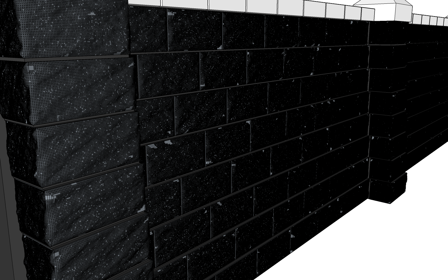
Welcome back! This is the story about achieving our long time goal of 3D printing realistic cut stone blocks. For the longest time it was out of reach, mainly because of my limited abilities, coupled with the limitations of the tools I’m using to capture the designs. But renewing the search to find new approaches to solve the design problems finally paid off recently!
Before we dive right in there’s some history we need to cover. It may seem like the long way around, but some backstory helps describe the problems looking for solutions, and the journey to find them. This all started long ago when we decided to use the concrete patch casting method for the walls of our Downtown Marketplace buildings.
We were off to a good start, learning from the mistakes of the first casting, and made two more. Painted, weathered, and detailed with 3D printed windows, doors, and display cases, they were impressive. We used mortar to attach them to concrete blocks for added strength against the Barkyard’s marauding German Shepherd population. Then other priorities stole us away.
I wanted to give proper credit where it’s due, but I’m sad to say the original site (rrstoneworks.com) I used as a reference for this technique is no longer online. They sold plastic pattern sheets and actually sliced real stones into what they called “Stone Sticks”. I have two boxes of them, with no way to get anymore of them. Need to check the “Wayback Machine” for anything useful…
It didn’t take long to realize the 3D printed PLA parts weren’t up to the task. The final nail in the coffin was the grand experiment, the Grand Hotel, also 3D printed from PLA. It lasted only days before it warped, got brittle, and fell apart. Another failure. The only thing durable enough to last over the years were castings. We detailed what it took to make that happen in this old post.
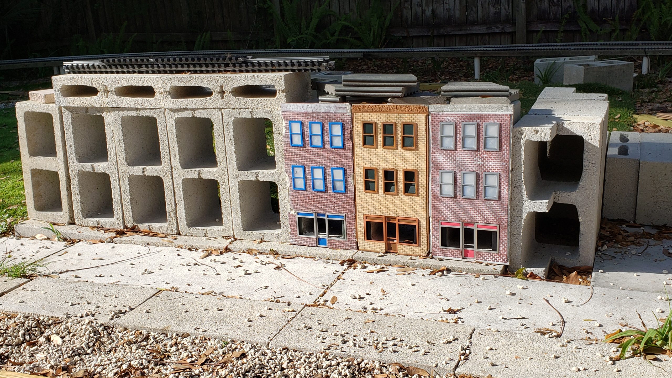
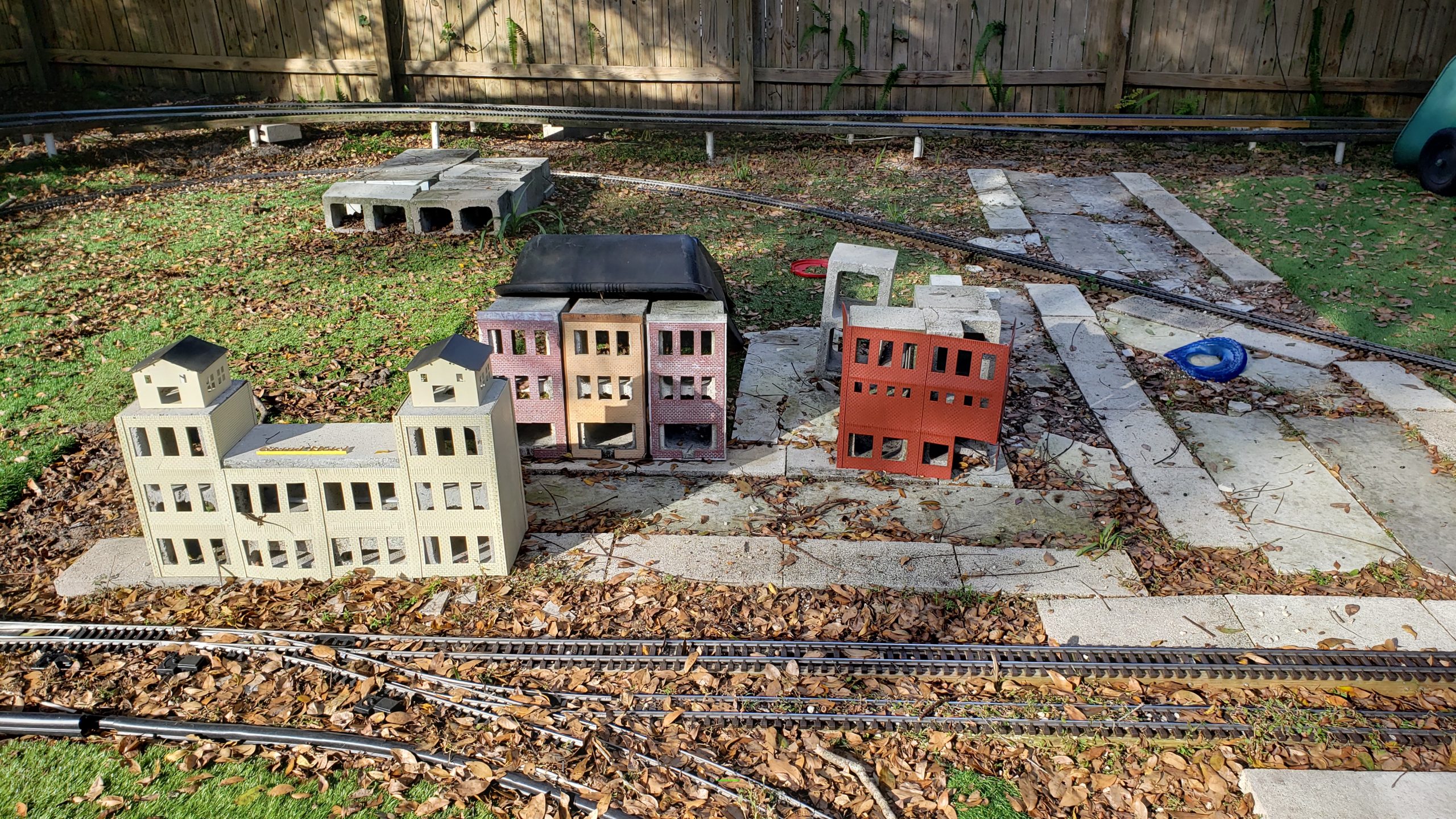
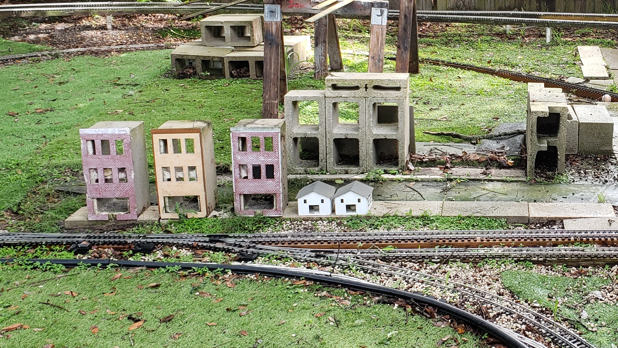
A Bit Of History
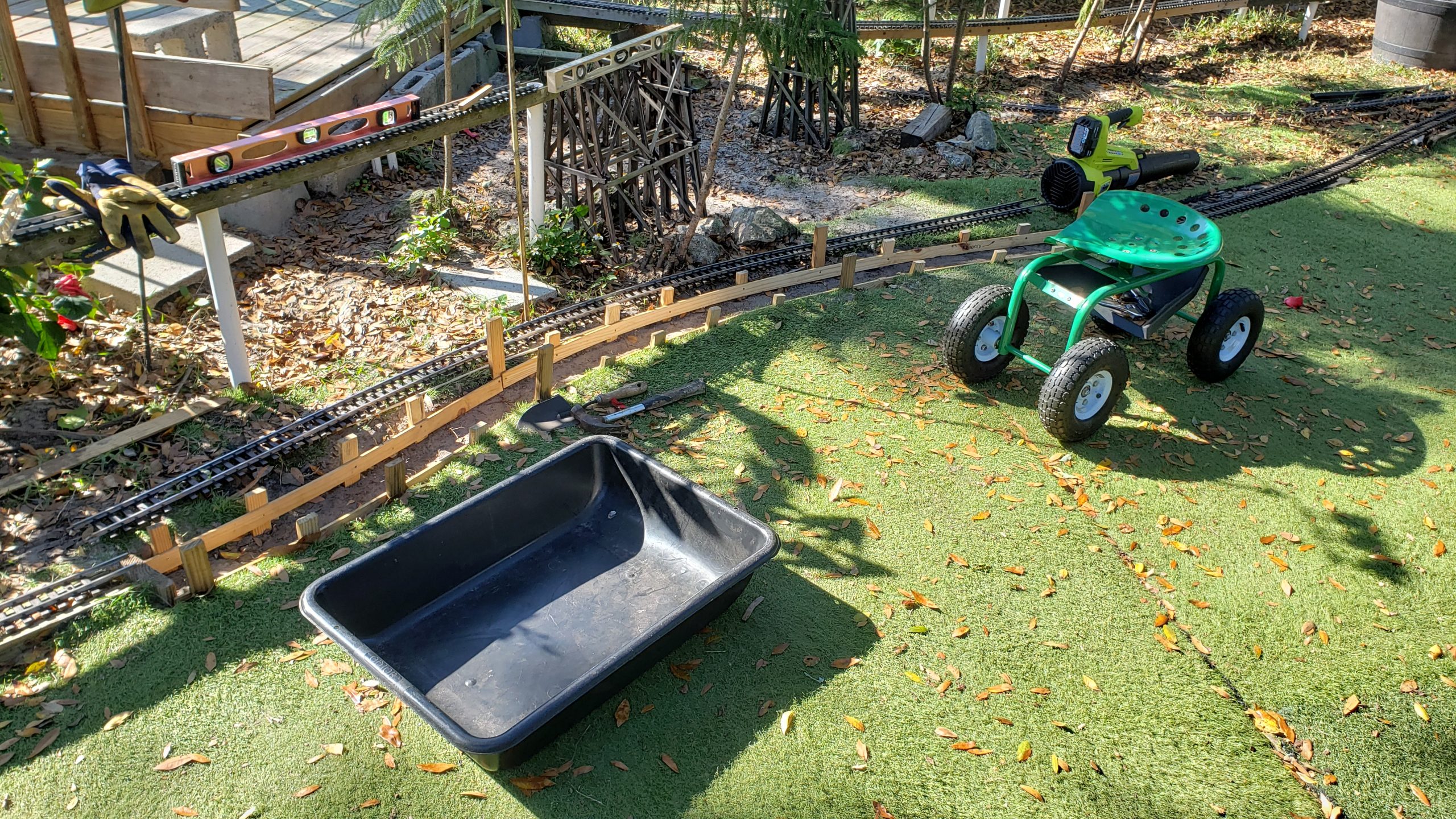
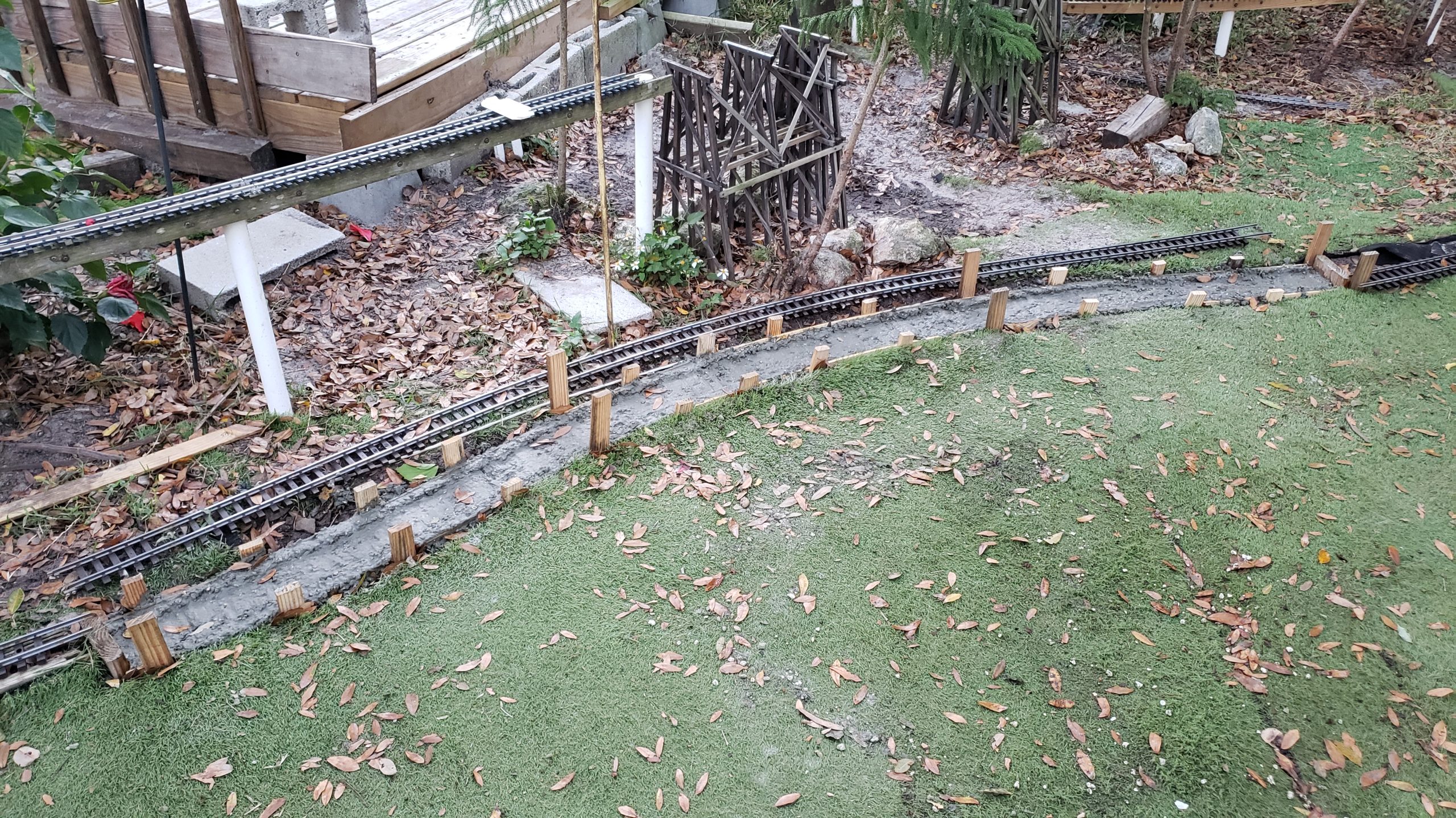
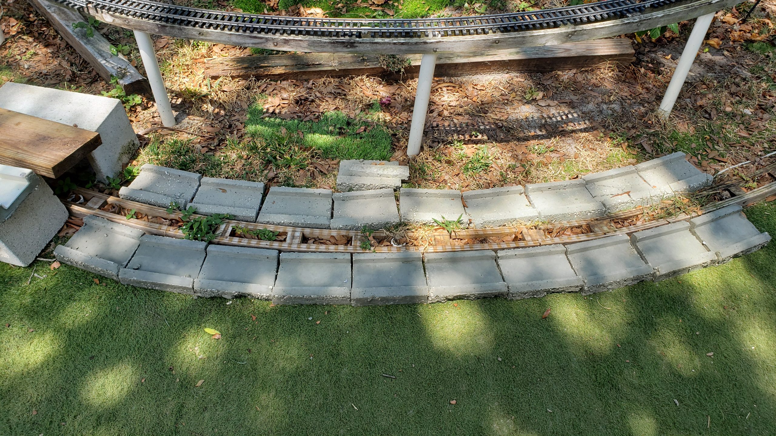
Fast forward a bit to casting retaining walls for the track to climb the grade it makes along the back fence and around the corners. We’ve already moved a LOT of dirt to create the embankments with the proper slope that sits beneath the tracks to support the retaining walls, pretty much following prototypical practice.
Struggling with designing casting molds for weeks, then months, the final version is still lacking years later. It lacks a definitive means of supporting the walls and connecting them together in a rugged fashion. It lacks a mechanism for adding on new segments to previously placed ones. Most bothersome is the lack of detail in the large, cut stone blocks that make up the wall.
The idea was to pour concrete into forms that would capture the castings and hold them in place while the concrete hardened then remove the forms. The design progressed about this far, printing mockups, and assembling them to help visualize what we’d encounter when doing this for real with mixed concrete ready to pour, detailed in this post. It was overwhelming. The design was tabled.
More Backstory
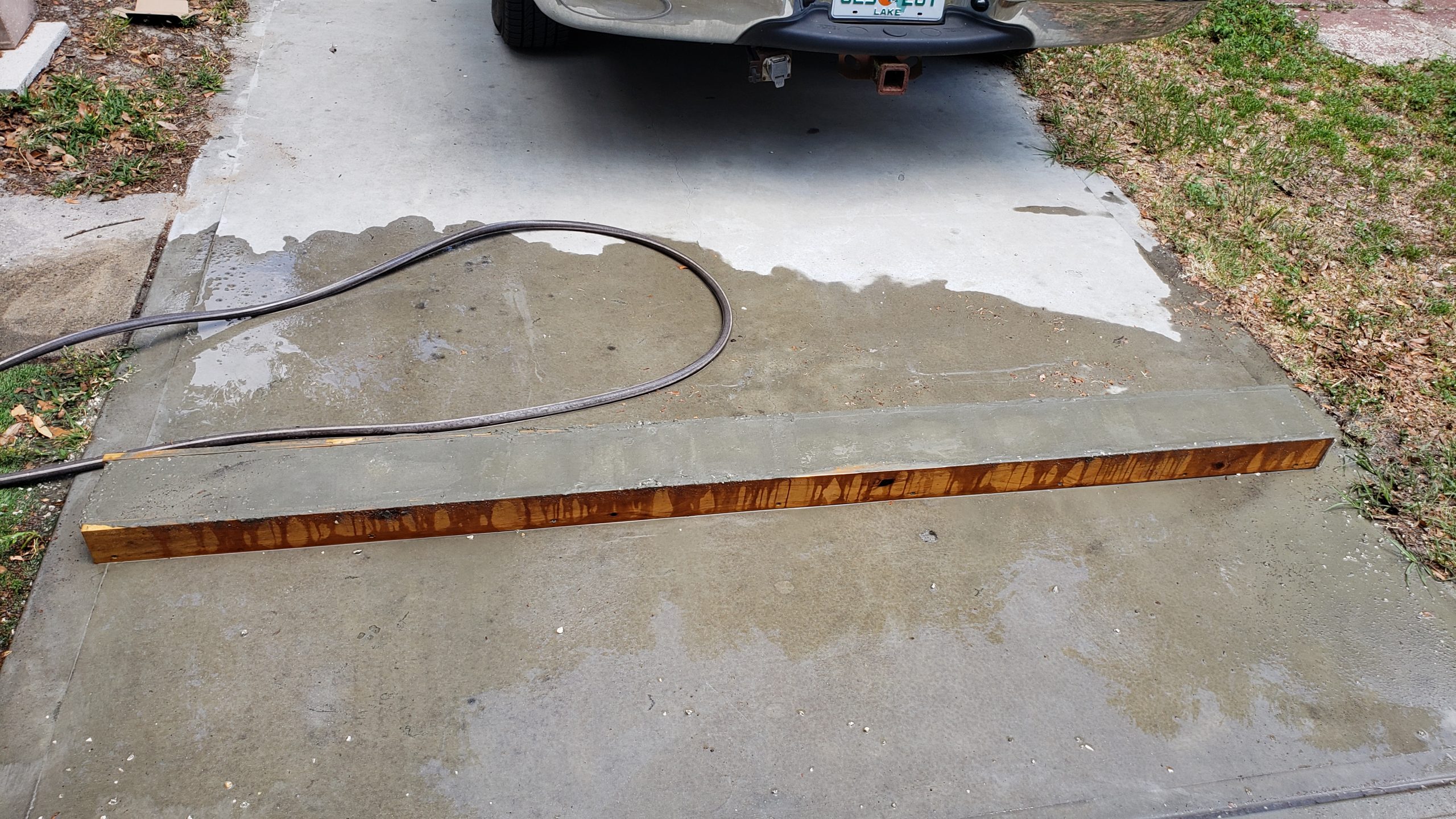
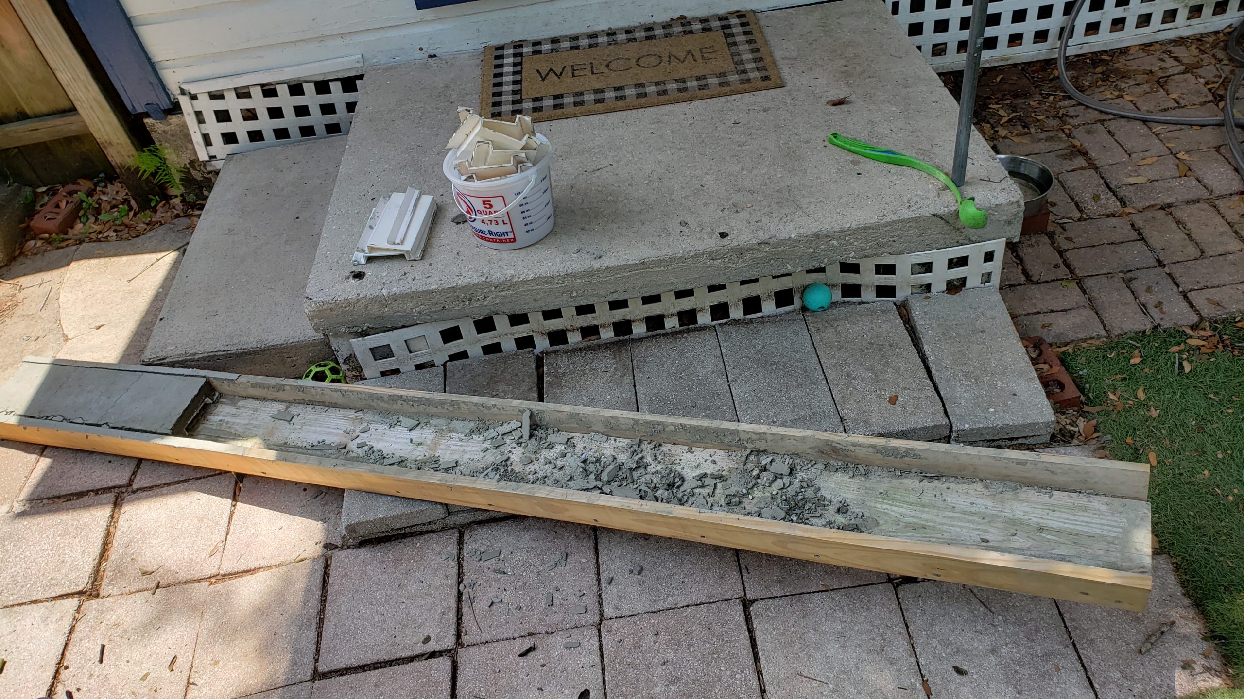
Fast forward a bit more to casting concrete roadbed bricks. Another learning process. Another shelved approach. The original approach was to form and pour in place, then “screed” the ballast profile into the wet concrete, like those concrete curbing machines do. That proved to be a lost cause, perhaps because the mix wasn’t wet enough, perhaps because I’m a novice and not a Mason.
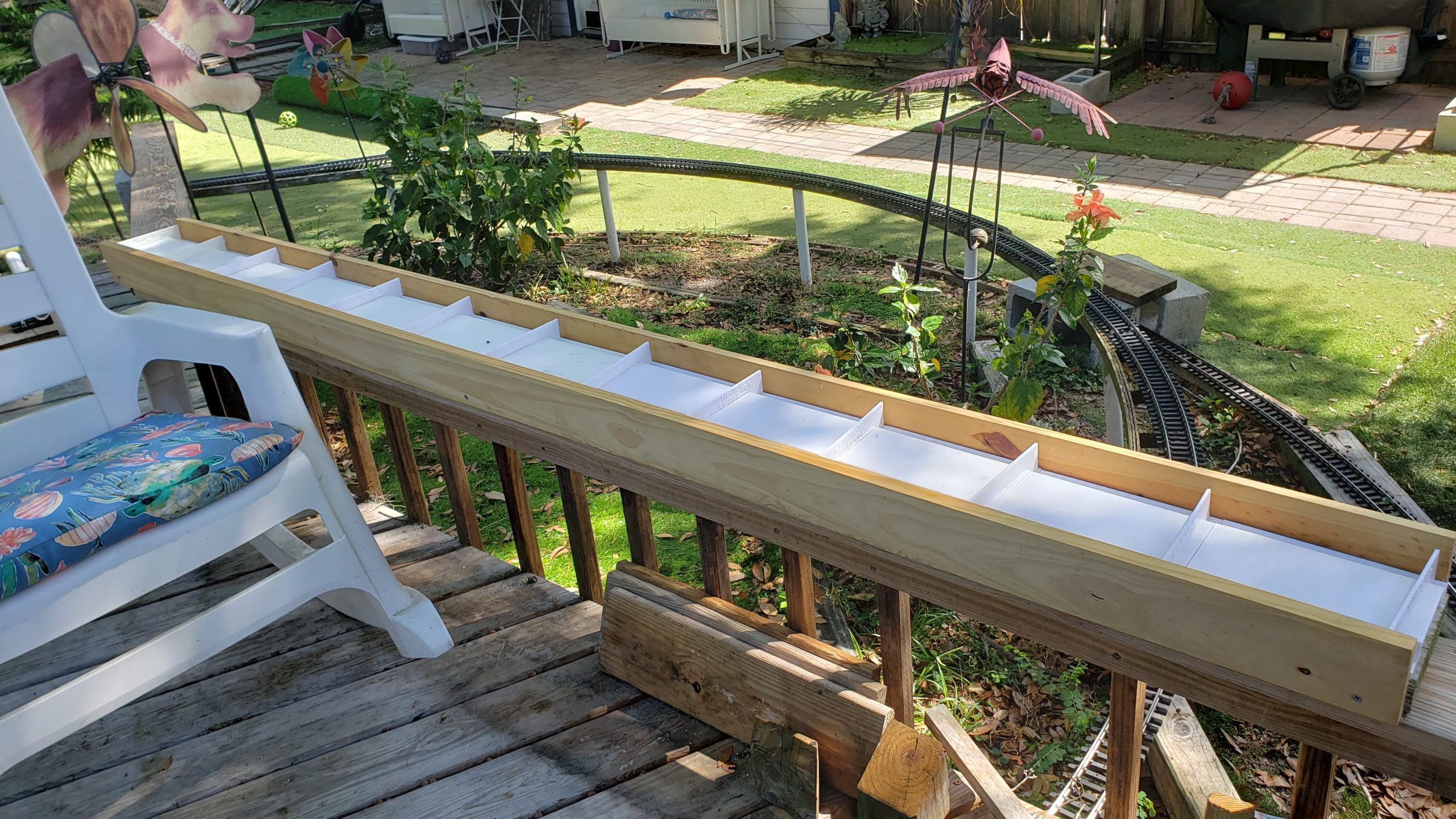
The next iteration was to create a long mold to cast individual “bricks” from the concrete. Screeding the top flat was much easier than trying to form a profile shape, but setting up the mold with all the pieces in place then cleaning up the mold afterward was tedious and time consuming. The mess of pouring concrete and the strenuous effort of mixing it adds up to more effort than reward.
Another drawback to any sort of casting is the amount of time involved, beyond the preparation and effort. It’s a series of “hurry up and wait” events that have to occur within a fairly strict timeframe. Once mixed, the pour has to occur quickly afterward. Then wait at least a day but not much more than that before removing the green castings from the molds. Time to find another way.
New Solutions To Old Problems
Previously I had designed and printed insulated sections for the SplitJaw™ clamps on the diverging routes of the wye. It quickly became apparent that PLA is no match for the Florida heat! Essentially the plastic slowly deformed until it simply gave out and the joints popped open with all the stress those curved legs of the wye were under. Another found out the hard way item.
Even PETG struggles with the heat. Nick was having similar issues with 3D printed parts for his “under hood” automotive applications, but he found a solution, High Temperature PLA (HT-PLA). He printed a set of coil mounts with it to test how well it stands up to the high temperatures in the engine compartment. The parts need “annealed” first though to give them their heat resistance.
As a test, he annealed one mount but not the other, then installed them on the engine. One melted. One did not. Needless to say annealed HT-PLA passed the test. He swapped out the melted one with another annealed one and they’re still going strong. I bought a roll of black HT-PLA filament a while back to see if this recent innovation will fit the bill for our needs too.
New Opportunities For Old Projects
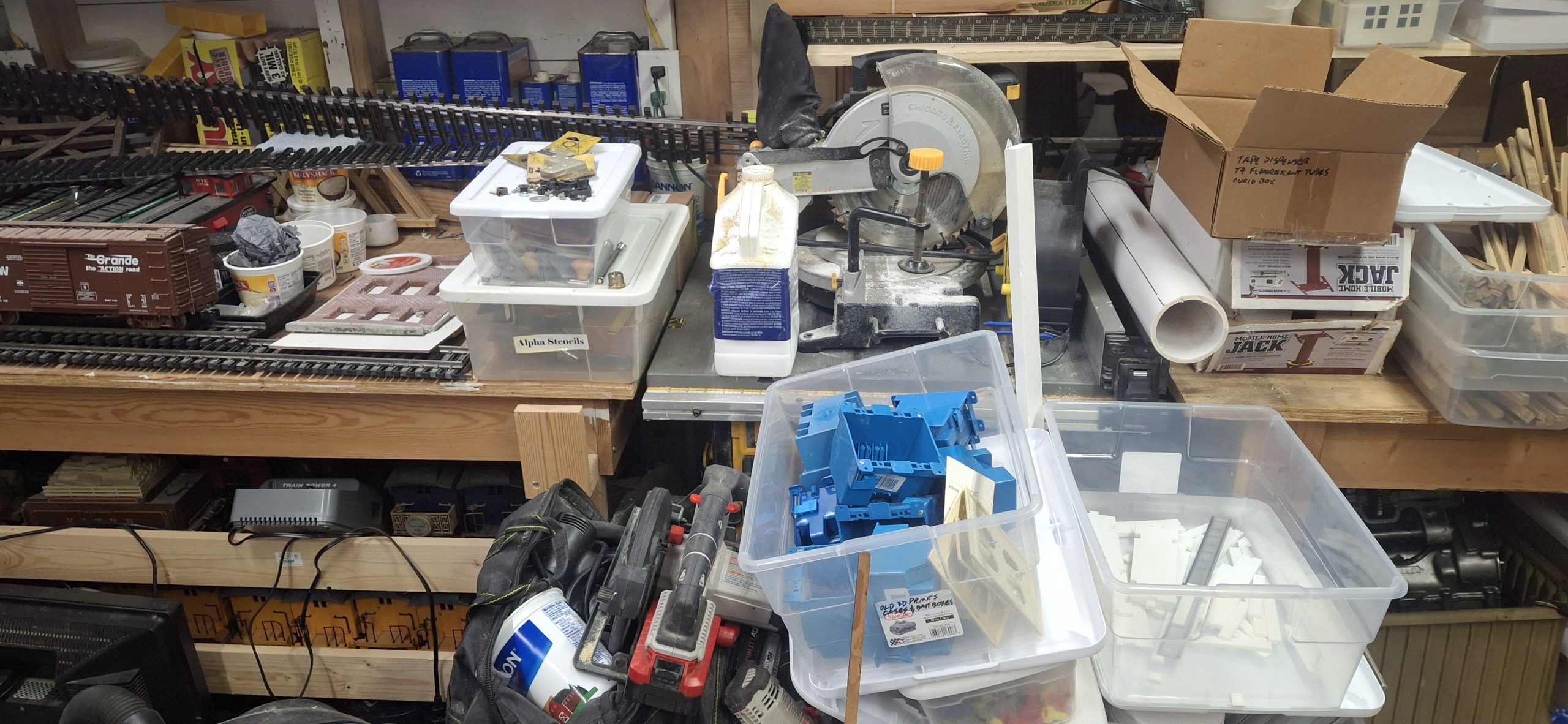
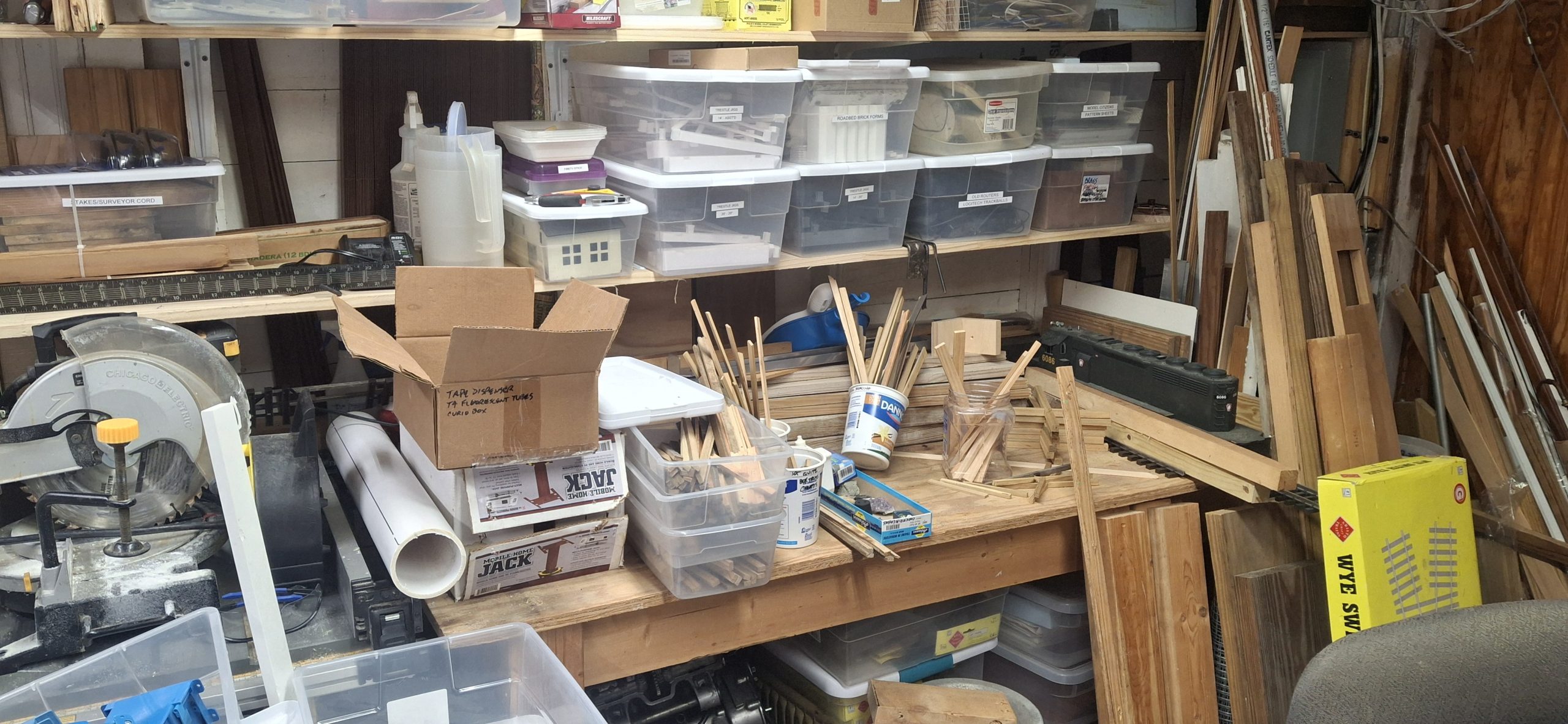
The bench space issue in the garage has delayed further casting, waiting for the bench to be cleared off, literally for years now. The reason for castings is twofold. First is durability when faced with constant pounding from three German Shepherds. The second is resistance to the brutal Florida heat and environmental challenges in general. Concrete holds up better than wood or PLA.
PLA lasts only days before warping. We found out the hard way with the Grand Hotel “skin”. We need a quick way to test this HT-PLA in the baking hot Florida sun. The quickest way there is to print something we’ve already designed, like one of those brick walls from the Downtown Marketplace stores. But instead of manually editing it to make it thicker, it’s time to try out OpenSCAD.
What better test for something that’s an exhaustively “manual intervention required” task than laying out a brick pattern? In a little over an hour the OpenSCAD model is rendered, exported as STL, and printing! While that’s printing, it’s time to learn even more about OpenSCAD and make the hard coded preliminary model more parametric.
Parameters like how tall and wide is the wall? How many windows? What scale? Brick dimension? Adding those features took a little more than a day to resolve, but now it’s totally configurable and can even create Downtown Marketplace storefronts! Just flip the switches and change the values and render another model, then export the STL and print!


Test Time
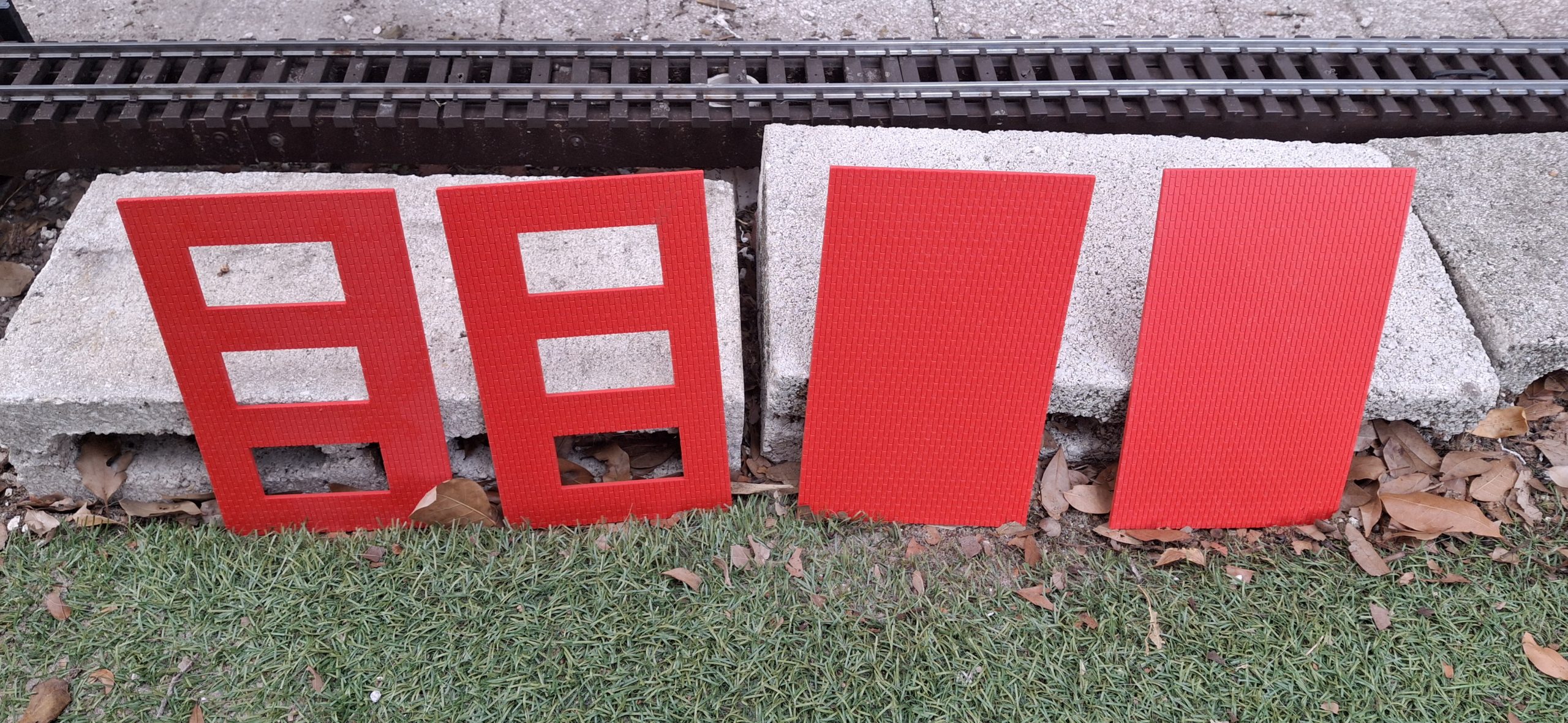
Before going any further with the grand experiment of HT-PLA, we need to test whether it will perform as required. I expect it to perform as well as it did for Nick. The first brick walls were printed using red HT-PLA. They were then annealed at 100°C (212°F) for 30 minutes as recommended by PolyMaker, the filament manufacturer, and allowed to cool back down slowly in the oven.
Glad I saved the “Easy Bake” toaster oven from the scrap heap. The only thing wrong with it is the broken handle, quite the nuisance when dealing with that hot glass door. It still works fine though. And it’s old school! Everything’s set using dials, including one of those timers that winds up and slowly ticks away, counting down to DING! It’s done. No modern computer crap to fail.
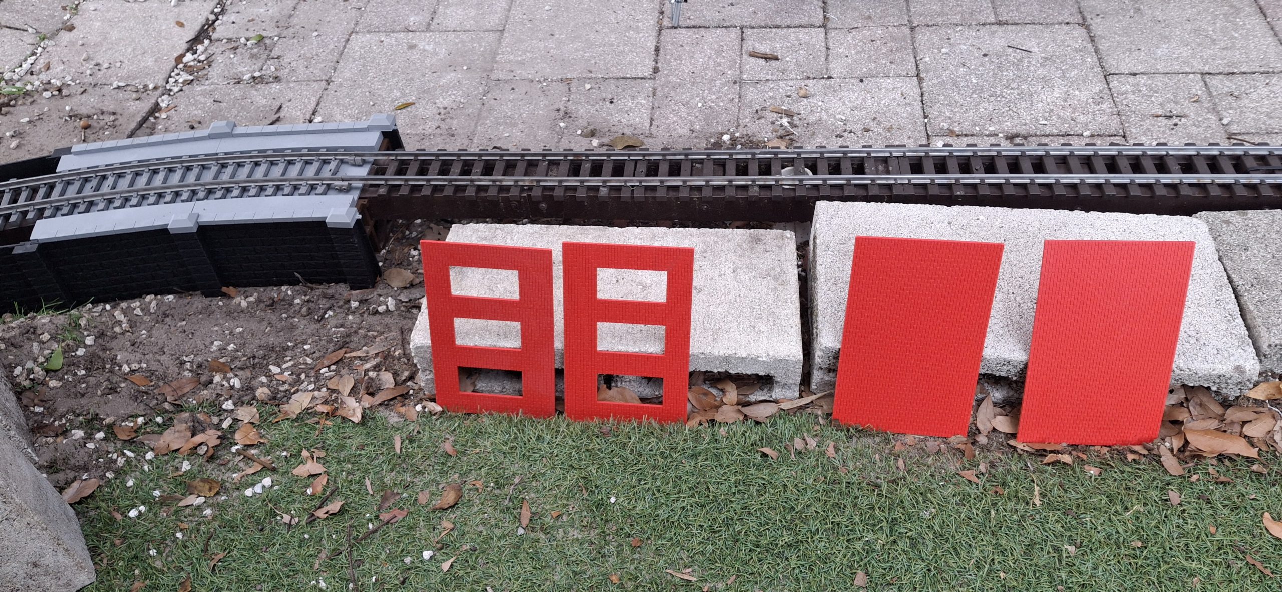
Once annealed, I set the walls out in the sun all afternoon, standing against the half high concrete blocks, where they can bend at about the halfway point under their own weight if they’re going to. Thinking the oven was plugged in when it wasn’t, the first brick panel didn’t get annealed, creating a side by side comparison test similar to Nick’s. That panel warped slightly into a convex shape.
But the rest of them passed the test with flying colors! WOOT! They’re only ⅛” (~3mm) thick and no deflection whatsoever! No warping. No distortion. No discernable changes at all. Nothing. Absolutely amazing! I tried re-annealing the warped one using a weight to try to flatten it back out, but it just warped into a concave shape this time. Oh well, at least now we know what to expect.

Riding The Wave Of Success
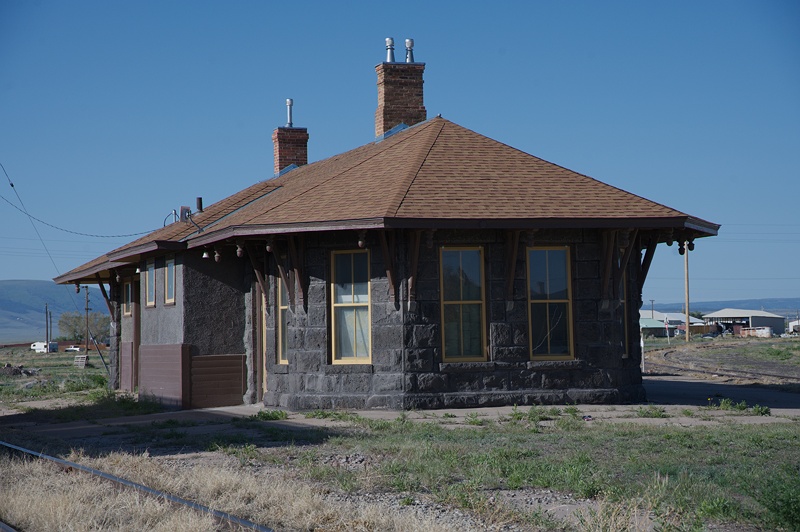
It’s the convergence of multiple successes coupled with a potential solution to the heat resistance problem that prompts pulling the cut stone retaining wall design out of mothballs. A quick search online reveals a post on the Model Railroad Hobbyist forum by Glenn Butcher about his solution to the exact thing I’m looking to accomplish! What are the odds?
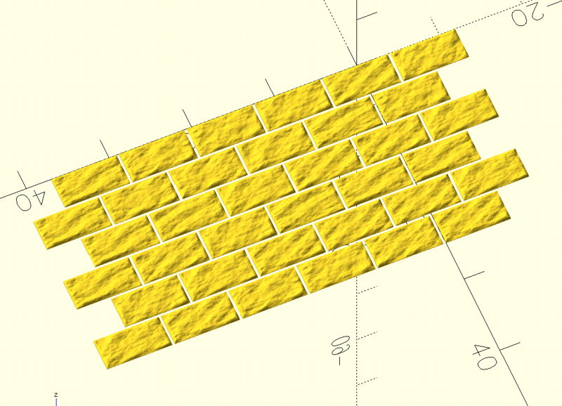
At first glance it’s way too overcomplicated as a quick solution, but then I see that Glenn has already created 20 textured stone STL files, and in OpenSCAD no less!. Now that’s the ticket! Without getting way too technical, he generated “height maps” to use as the textures using a technique the makers of Star Wars used to generate realistic, computer generated terrain.
In fact, the approach is captured in a publicly available library, libnoise, that anyone can use in their own programs. That’s exactly what Glenn did then shared his work, noisetool, online. Sounds good, right? The drawback is those height map files for OpenSCAD are tens of thousands of lines long. Each. Now put 20 of them in one program! Good luck scrolling through something that big!
Making It Work
I know, engineers, right? I thought I over-engineered things, but Glenn takes it to a whole new level. That’s a good thing! Each of these textures is meant as a 3″ x 6″ HO scale wall, but our cut stone blocks are ½”x1″, a 6:1 scaling factor. If we want one out of six in two directions, 6 x 6 = 36, and we only want one of them. We could throw out 35 of 36 values and still have plenty of detail.
In an attempt to work around pasting all those huge files into OpenSCAD and simply import a series of 20 files that captured each of those height maps as solid models I used an online tool that converts STL to OpenSCAD files to be able to import those 20 STL files as modules I could include in OpenSCAD and then arrange them programmatically.
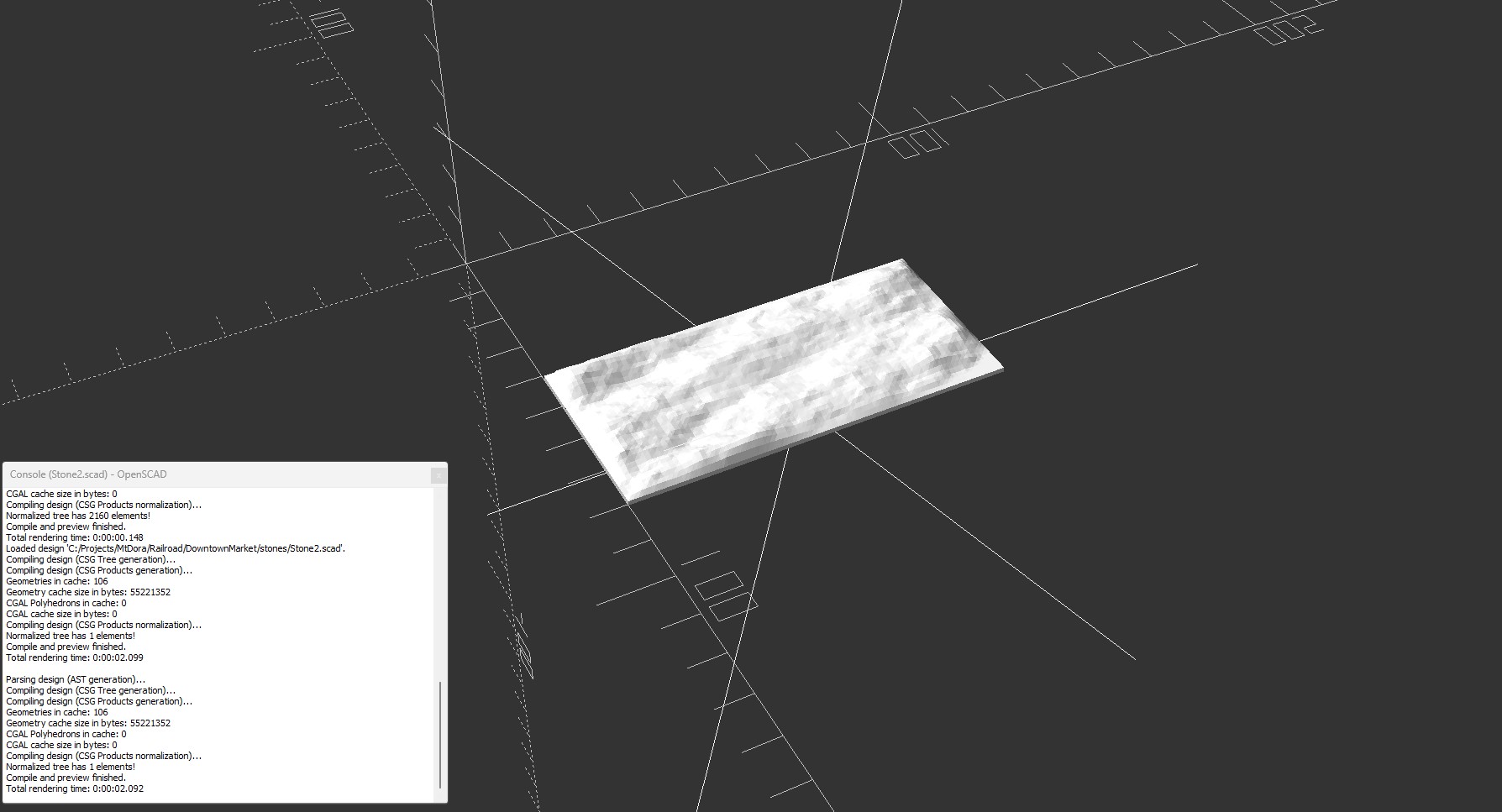
I get it all working up until I try to actually render it to export the STL and get a “Thrown Together” error for every stone! Not sure what that means or how to fix it. A quick search says I should try a development version newer than the 2021 release version. I don’t have the time to throw at getting a development version of the program working. This was supposed to be a quick win.

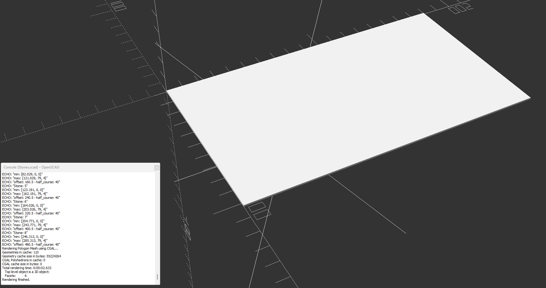
Next!
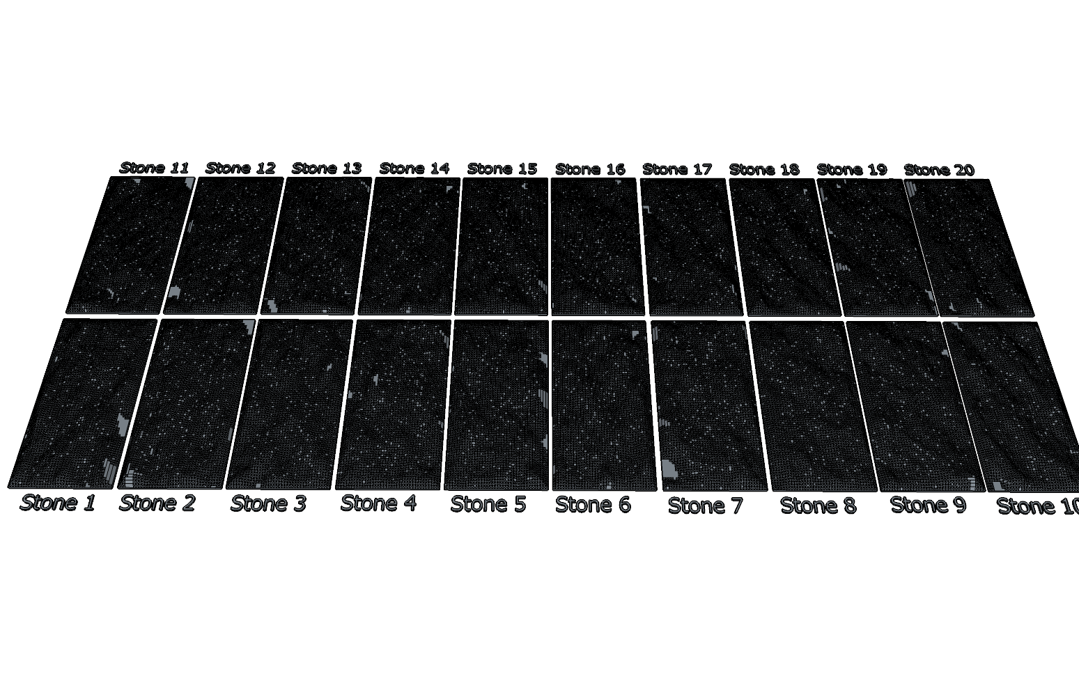
Well that was a LOT of wasted time for absolutely no reward! Time to get it working in SketchUp. I imported the series of 20 STL files that captured each of those height maps, one at a time, into FreeCAD. Once there, I created a mesh from the STL, optimized the mesh, and then created a solid from the optimized mesh and exported them as .dae design file models SketchUp understands.
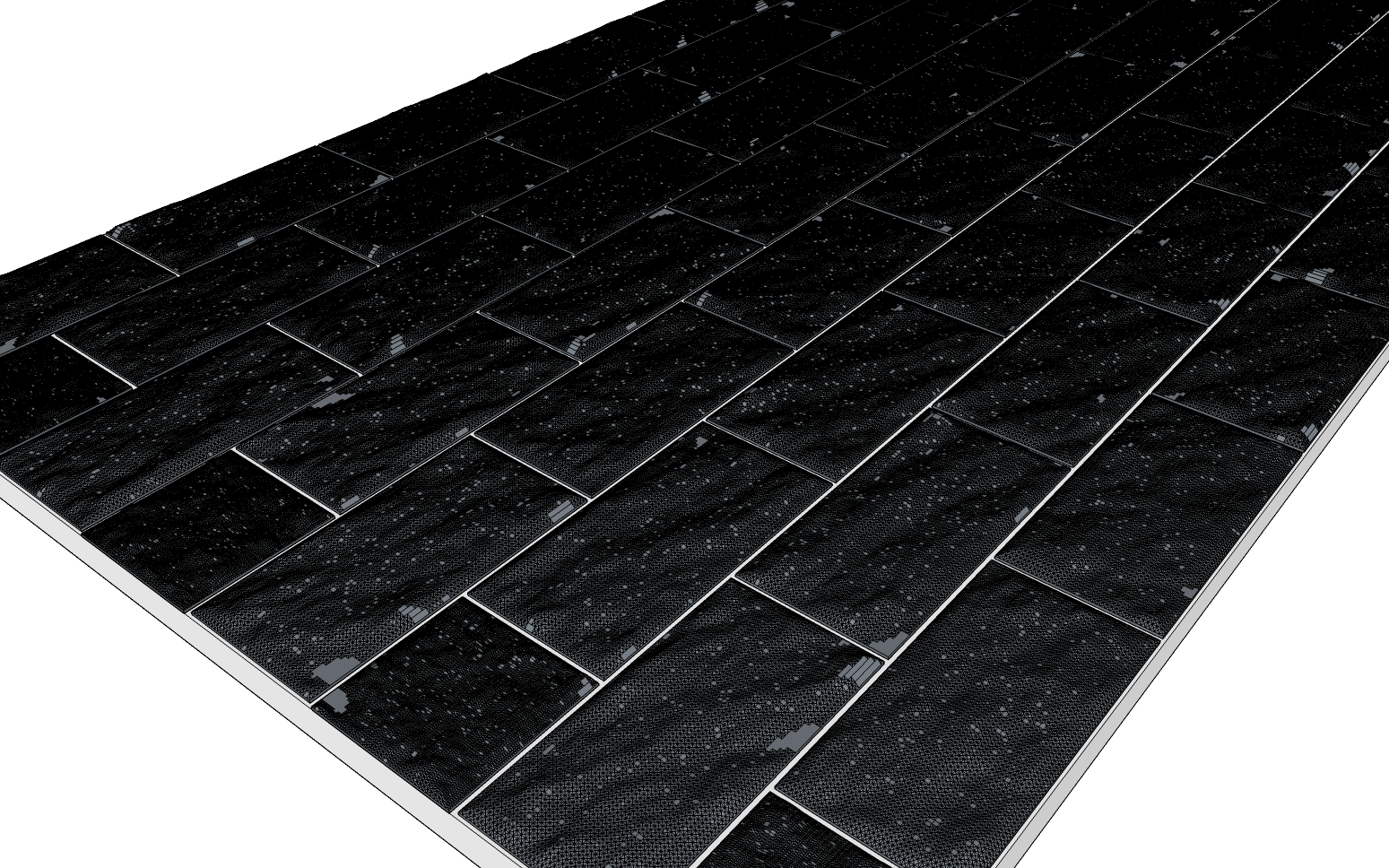
Alright, I promised I wouldn’t get too technical, but it’s worth noting how I created the models. Rather than write a program to sift through all that data and throw out what we don’t need, I just pulled the solid models exported from FreeCAD into SketchUp. From there they’re scaled and the stones manually arranged into our familiar 4″ x 7″ retaining wall segments.
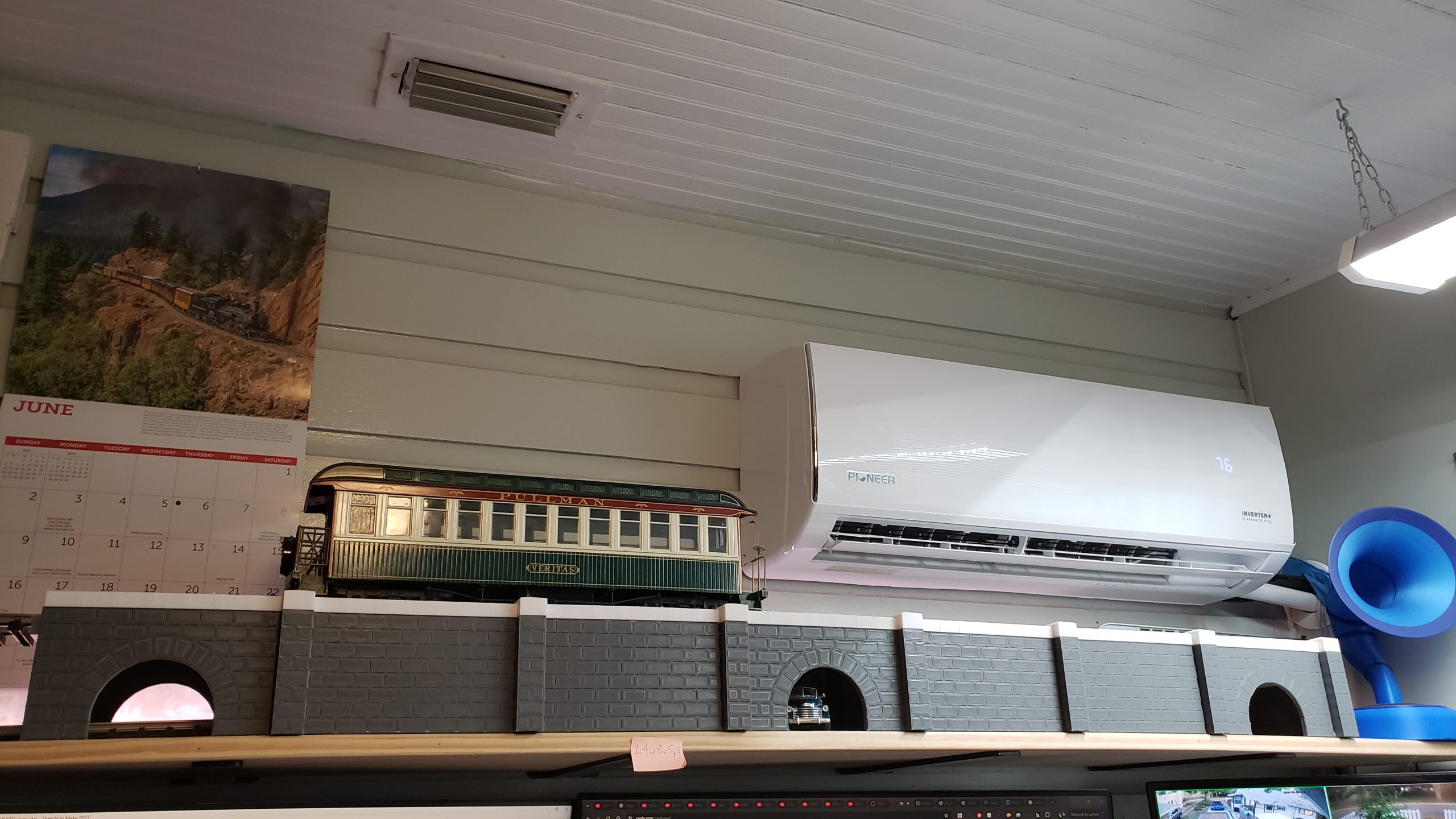
Next HT-PLA test, black cut stone retaining walls. If anything doesn’t stand up to baking in the hot Florida sun, it’s black anything. Anyone who has a black car interior knows how scalding hot those surfaces get after baking in the sun all day. Can’t even touch the steering wheel for minutes, even after the A/C is blowing cold on it, and even then you wish you had gloves.
Adding Realism
It takes some time to get all those stone models imported and resized to fit our existing retaining wall dimensions. It’s soon apparent there’s WAY TOO MUCH DETAIL! What used to be snappy response times are now so sluggish I’m wondering if I actually pressed the key or clicked the mouse. In any case, I lay out a pattern of blank, mock stones then replace them with the imported ones.
One by one I substitute the textured stones until I’ve used all 20 of them, the first three courses out of eight. The next three courses I start at the beginning again, but flip them along their green (Y) axis, from left to right, effectively making them a mirror image of the originals. The last two courses use a similar approach, except this time flip along the red (X) axis, mirrored from top to bottom.
That leaves the “half” blocks at the end of the staggered courses. I chose a handful of stones that look the flattest, with the least amount of detail, because sizing them to half their length will stack twice as much detail in the same amount of space. It works out well and the mock half blocks are replaced with the actual stone models in a similar fashion to the full blocks.
There! Now we have a “flat” wall with realistically textured cut stone blocks that we can test with. Well, once the STL is exported, sliced and 3D printed we do. First it goes into the Easy Bake oven to anneal. Then it’s punished by the Florida furnace. Fingers crossed this will hold up to the heat. The flat wall passes with flying colors! It sat out all day, then overnight, and again all the next day.
Testing While Adding More Realism
Meanwhile I’m working on making the flat wall sloped to match prototypical construction. When I say “flat” I mean the blocks are stacked directly on top of the course below, with no lean either way. The prototype calls for an inward lean to account for the increasing forces exerted by more and more dirt the deeper down it goes. The sloped profile is more realistic than the original flat version.
Each new iteration of the evolving design gets printed and added as a new test subject. All the black test subjects have been baking in the sun all week with no discernable changes. Absolutely awesome! That means using the HT-PLA for tie strips is a possibility too! Time to try printing the switch ties for our new curved switch with it.
Another practical use is rebuilding the Downtown marketplace using HT-PLA instead of castings. It may not save much time over castings, each 5″x8″ wall segment takes hours to print, but it’s far less messy! And it certainly doesn’t take as much prep and cleanup time as casting. But we’ll save all that for another post.
Some Caveats
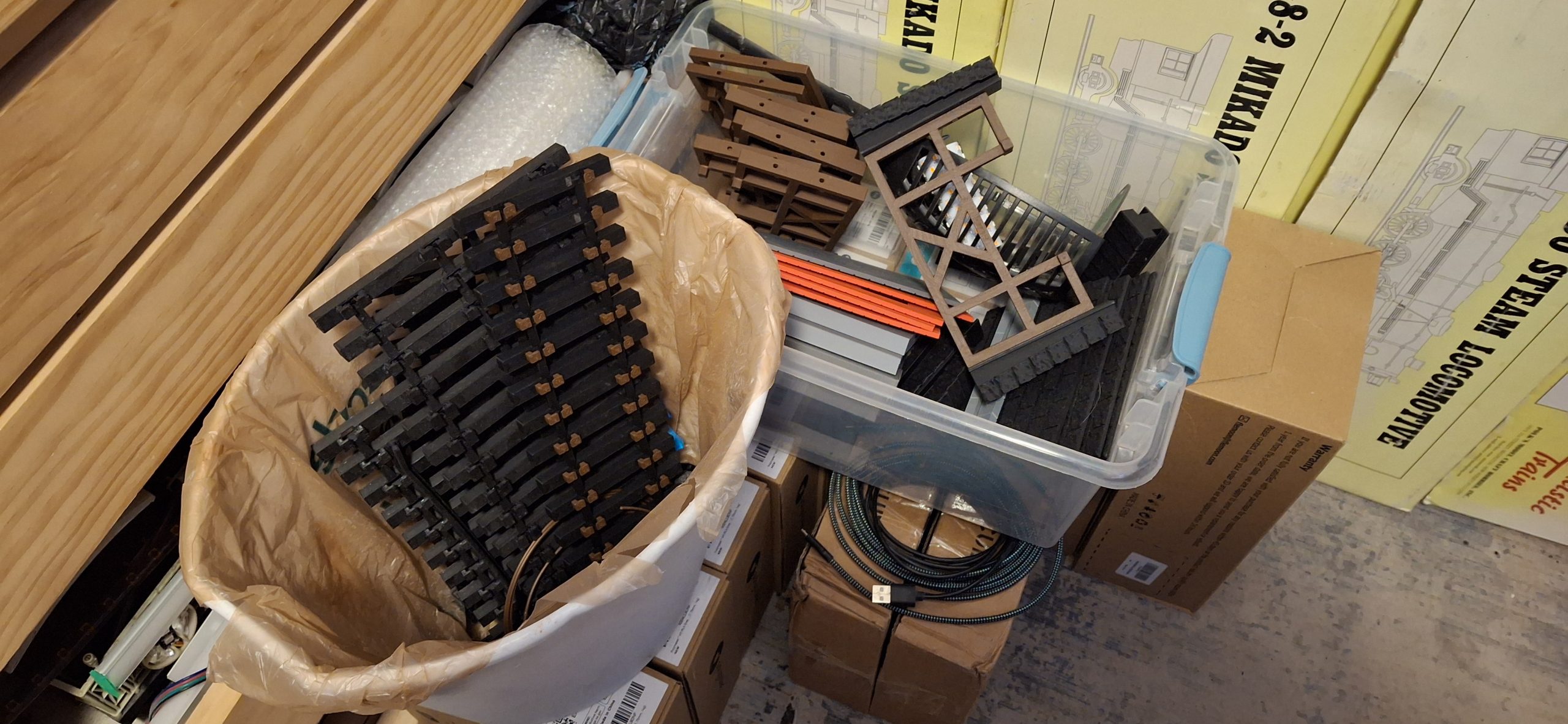
There’s something to be said for getting it right the first time. Something that seldom happens. I have a bin full of useless prototypes that didn’t make the cut. May as well get used to burning through at least a 1kg spool of filament prototyping a design to get to the production version. Or should I say a production version? There’s always that one last tweak to add…
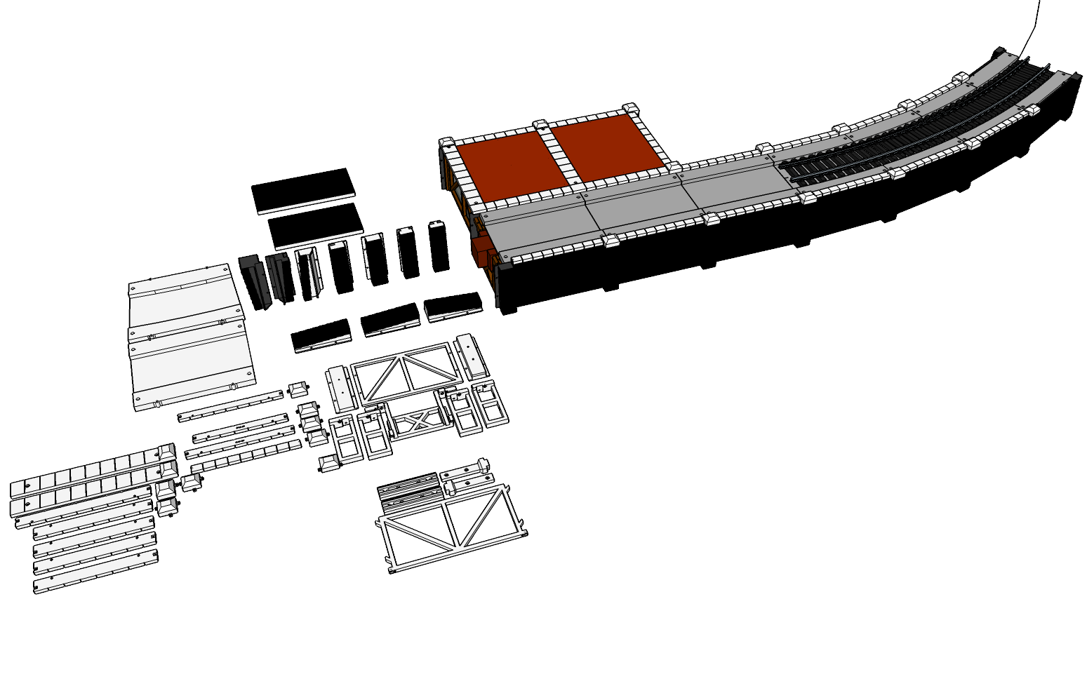
Each part of this design has evolved to suit the requirements of the station siding, and now by extension, the ever evolving station platform. But I’m getting ahead of myself again. The initial design elements are primarily the walls and pillars that join them together, the track deck and capstones, and the underlying frame that ties everything together around the stringers.
Originally the walls were glued to the pillars. More like solvent welded, similar to using plastic model cement. But it quickly becomes obvious after about four wall panels that a wall 10′ long can’t easily be moved all together all at once without breaking apart. Time to rethink the design. So now everything is modular, held together using M2.5 stainless steel socket head cap screw hardware.
Modular Design
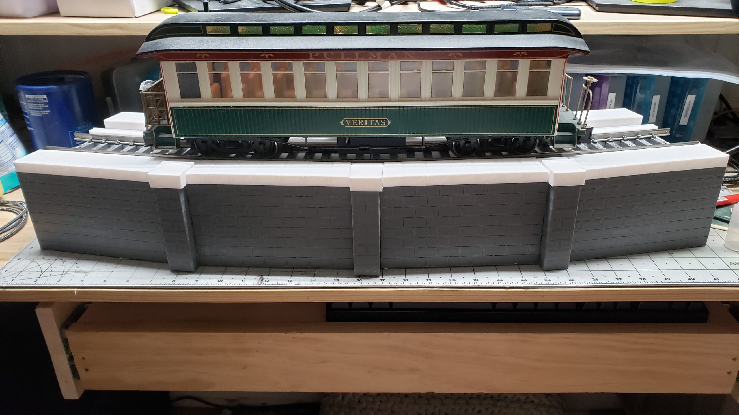
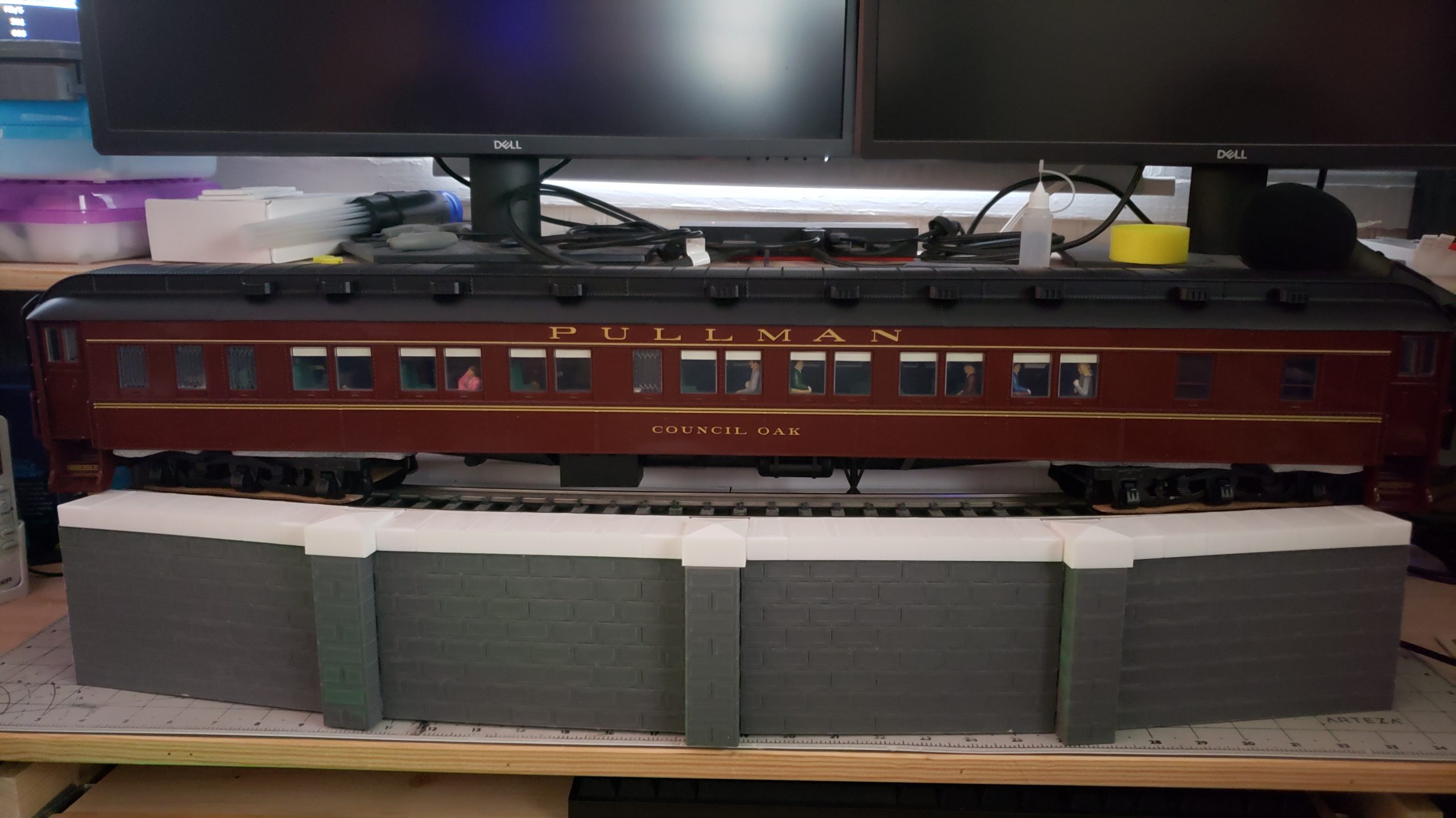
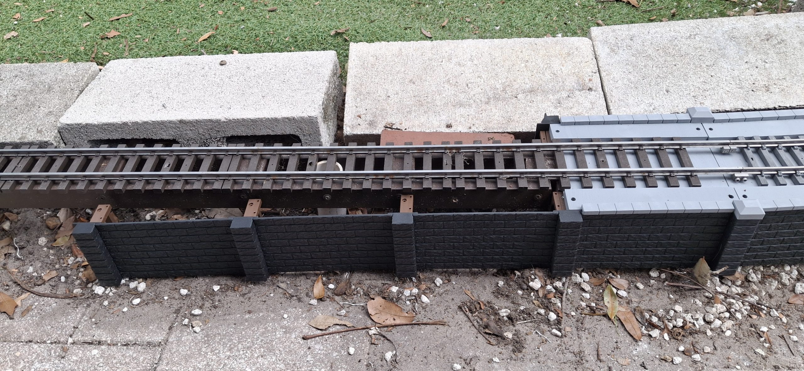
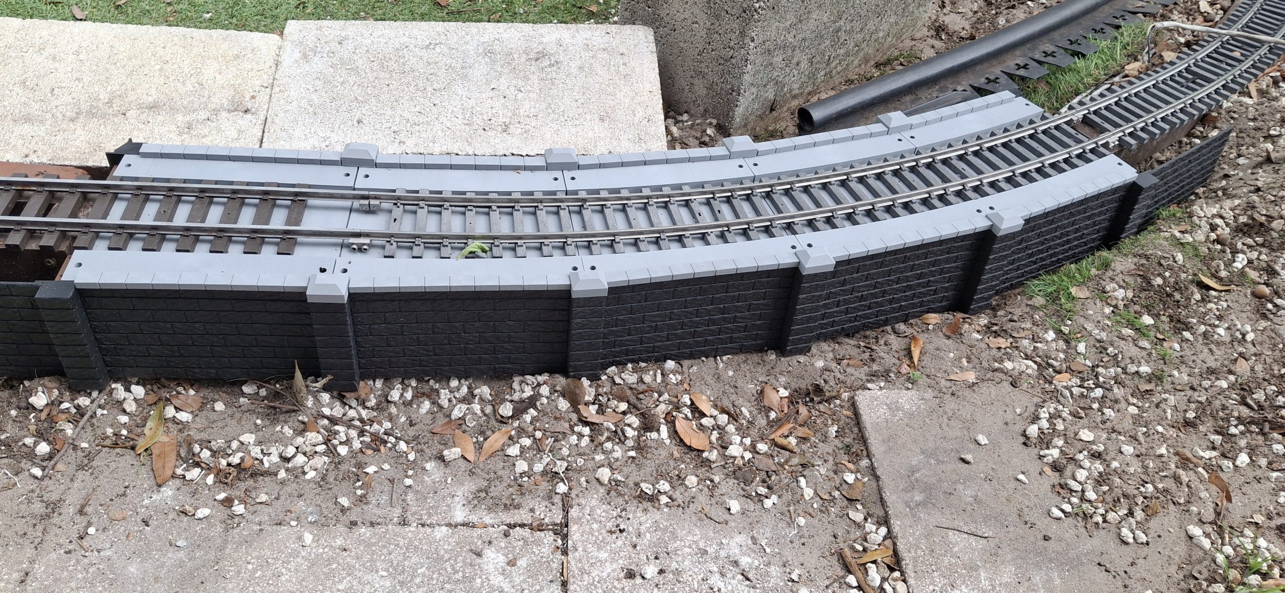
That four wall panel section is still sitting on the office book cases. I just can’t bring myself to throw it away yet. Why four panels? Because that’s the magic number of roughly 8″ (~20cm) sections it takes to make a complete 10′ diameter track section. The pillars are designed to angle each wall panel from the last by 7.5°. Four gives a total of 30°, the extent of a 10′ diameter curved track section.
Two M2.5x6mm screws hold the pillar to each wall panel, a set for each panel on either side of the pillar. The transition to tangent track and remaining walls have another pillar design that has no included angle so the wall panels remain straight and parallel to one another. There is one exception for the inside transition from 10′ diameter, mainly to accommodate track deck mounting.
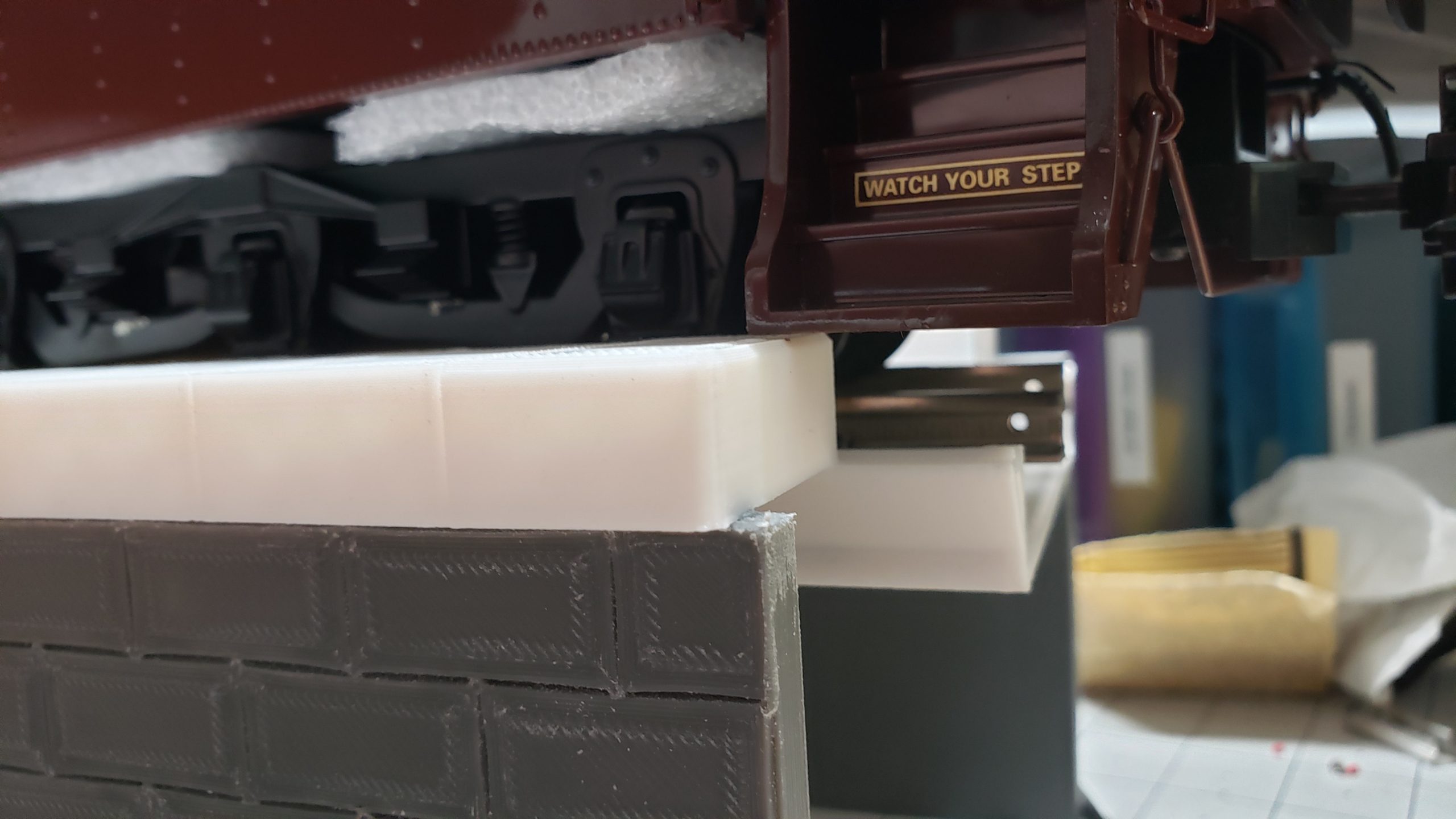
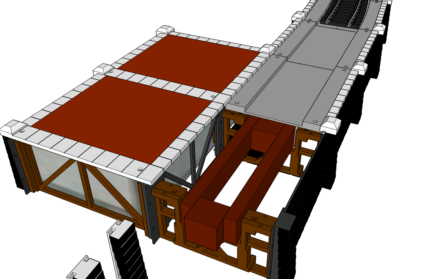
The track used to sit directly on top of the stringers, but now it sits in a “trough” in the track deck, as deep as the ties are tall. The “floor” of the trough the ties sit in is ⅛” (~3mm) thick and now sits directly on top of the stringers. The track is not mounted down to the track deck, but rather left free to “float” in the trough, and the track deck itself mounts to the underlying frame.
Keeping Things Where They Belong
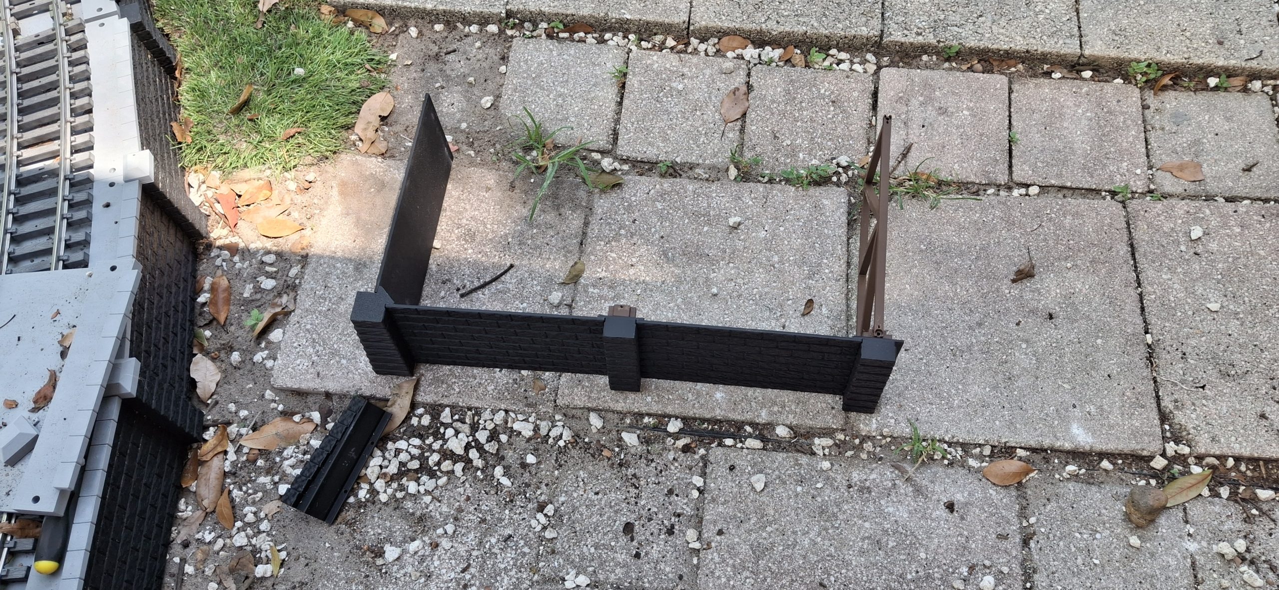
The frame surrounds the stringer, the main reference for track placement, holding things together and where they belong relative to the stringer. The frame is a three piece design. Two tall sections that mount to the back of each opposing wall pillar using two M2.5x8mm screws. The third “Twist Lock” piece pulls the opposing mounts together and locks the assembly around the stringer.
Leaning the twist lock back at an angle allows the set of “hooks” at the bottom to catch and hold just inside those two mounts, then by twisting it up into position, it locks everything together, including the wall pillars. The twist lock section is secured to the mounts using two M2.5x10mm screws from the top, mainly because that’s about the only access left once everything’s assembled.
The track deck itself mounts to the underlying frame using four M2.5x10mm screws, covering and blocking access to those two screws securing the frame pieces together at either end of the deck. The socket heads are recessed into the raised portions of the deck on either side of the track that forms the trough. Eventually they will be concealed by a fence, roof supports, or some other cover.
The capstone strips are secured to the deck from beneath using M2.5x16mm screws. Once the deck is mounted to the frame, they are no longer accessible. The single, larger pillar capstones can be held in place by simply inserting their built in tabs into the slots in the underside of the deck capstones. They can also be secured using button head cap screws, but it generally isn’t necessary.
New Challenges
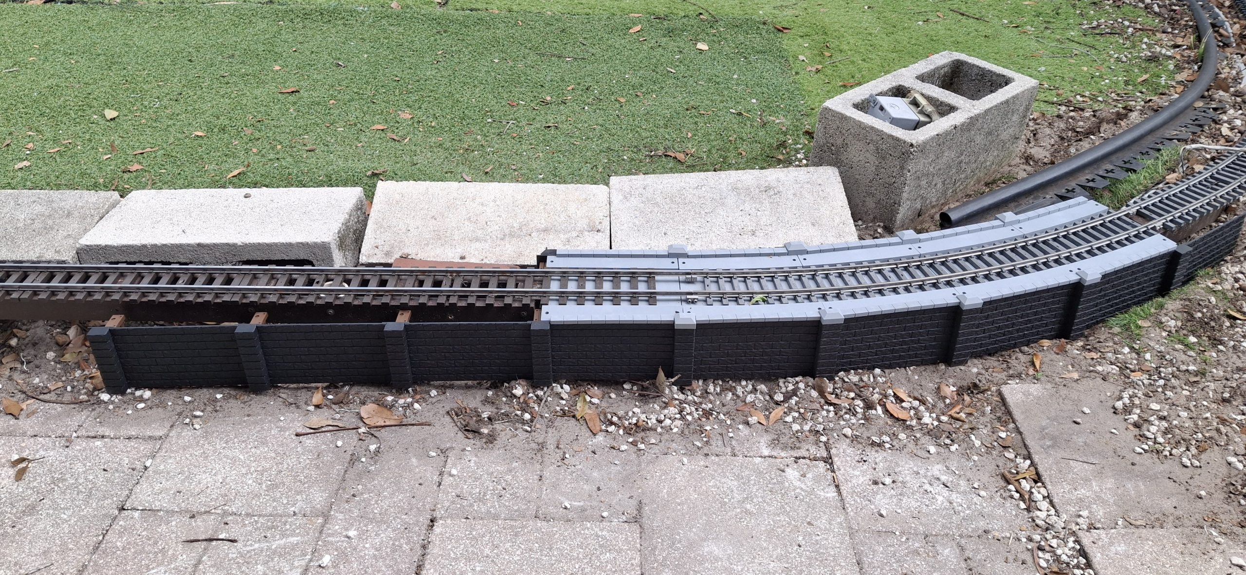
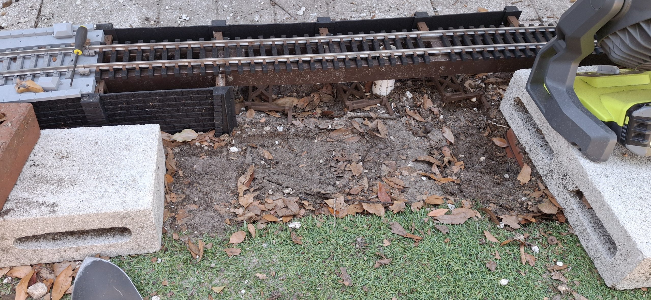
With enough 10′ diameter sections in place to account for the surrounding grade increasing to meet the track level and the kinks in the transition to tangent track hammered out, it’s time to think about the station platform and how to connect it to what we have so far. More specifically, how to incorporate the old station platform 4″x8″x16″ half height concrete blocks into the new design.
The whole sad story about how nothing’s left of the original station platform was left out of the earlier history lesson. The abridged version is there used to be raised bed planters along the entire length of the patio. Those blocks sat between them and the track stringers, with a roof of sorts from the planters above acting as a covered station platform.
The planters were removed long ago, leaving just those blocks along the station siding track. Because the track sits roughly 4″ off the ground, any kind of platform would need a good bit of support or dirt fill beneath to hold up to the constant pounding from the pups. We already have all those blocks just sitting there anyway, so why not incorporate them into the design?
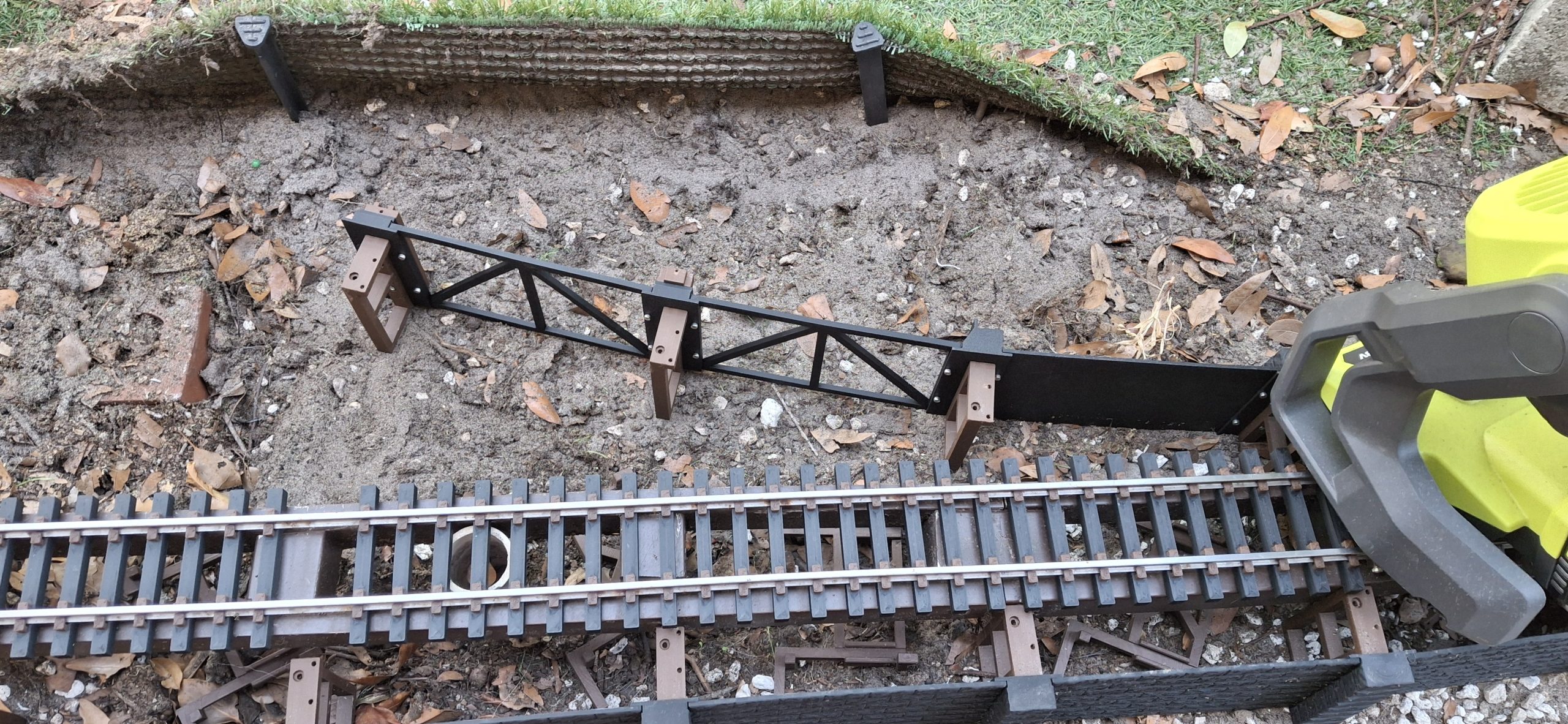
Transitioning From Curved To Tangent
Before we can use those half blocks, we have to transition from the curved approach to tangent (straight) that will become the station track alongside the platform. This is the exception for the inside transition described above. The exception it refers to is where the curved track deck meets the tangent track deck.
Originally the thought was to have a transition track deck and transition pillars. Partway into that design it was discovered that not only would it take one transition track deck, it would need two of them and both of them would be different! Basically one to go from 7.5° apart to 3.75° apart, and then from 3.75° to straight and corresponding pillars to match. But that didn’t make sense.
The current design simply reuses the curved and tangent track decks along with a regular 7.5° pillar outside and the new transition pillar inside. The inside transition pillar has a 7.5° angle too, but the stones are offset from the middle of the angle to account for the track deck mounting locations. I feel like I’m waving my hands again, but this gets us from curved to straight using fewer parts.
By shifting the mounting points on the inside transition pillar to accommodate the standard track decks, it eliminates the need for at least three or more additional, specialized parts, only useful in this one situation. Too bad I didn’t think of it before designing a number of those specialized parts first and then having to toss them out after wasting all that effort.
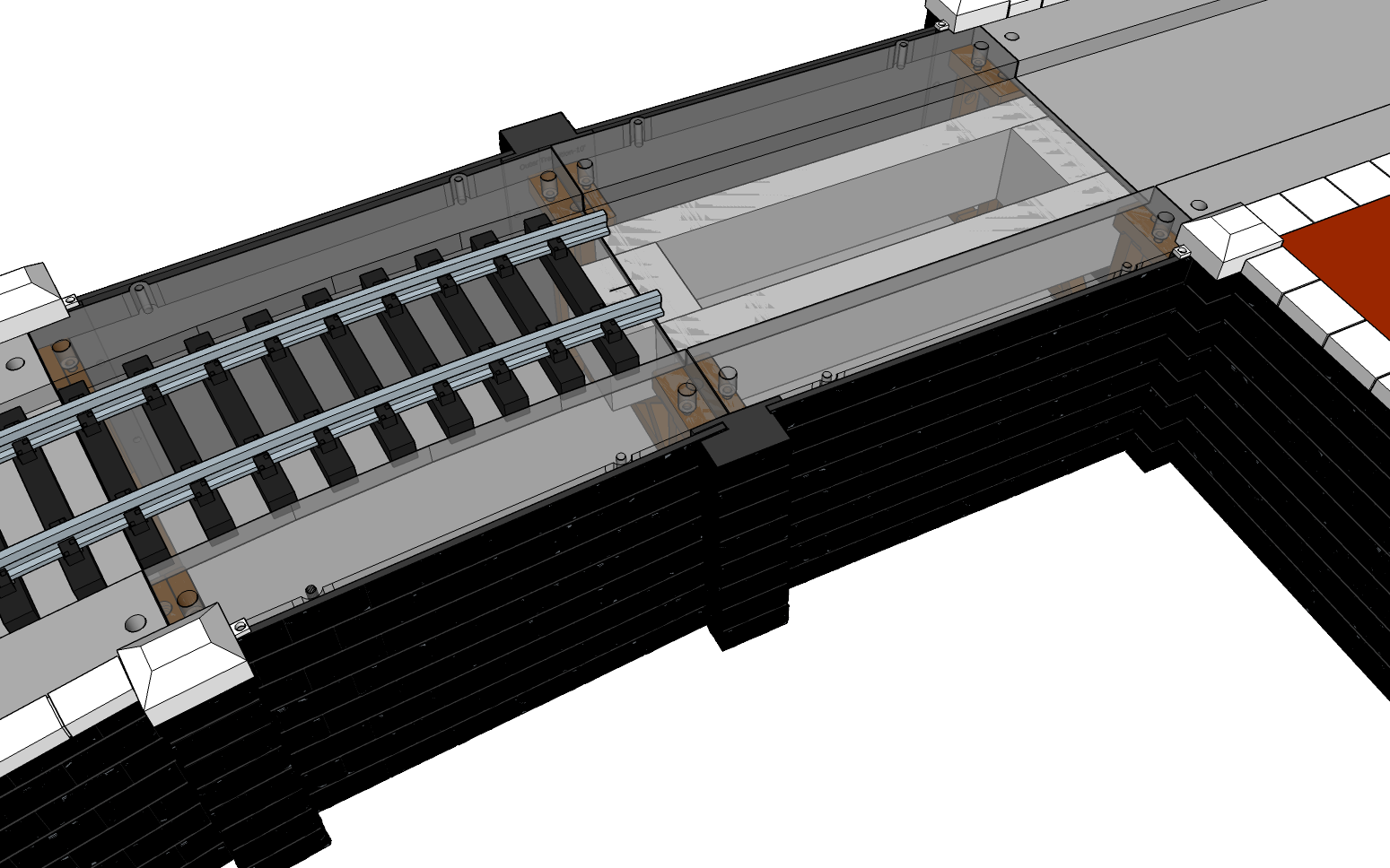
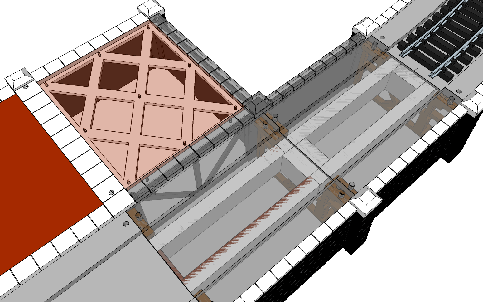
Transitioning To A Platform
So now that we’ve transitioned from curved to straight, before we can use those half blocks, we still have to transition from the current approach track with retaining walls on either side to a platform with a retaining wall on one side and a station track on the other, the station track with its own retaining wall on the other side, continued from that side of the approach track.
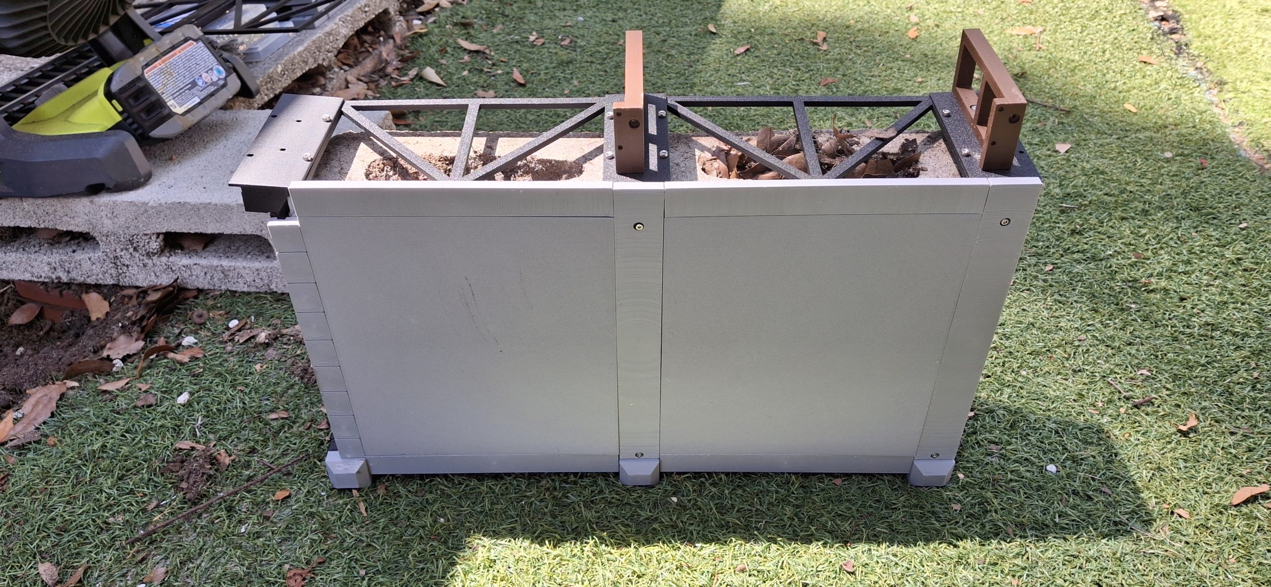
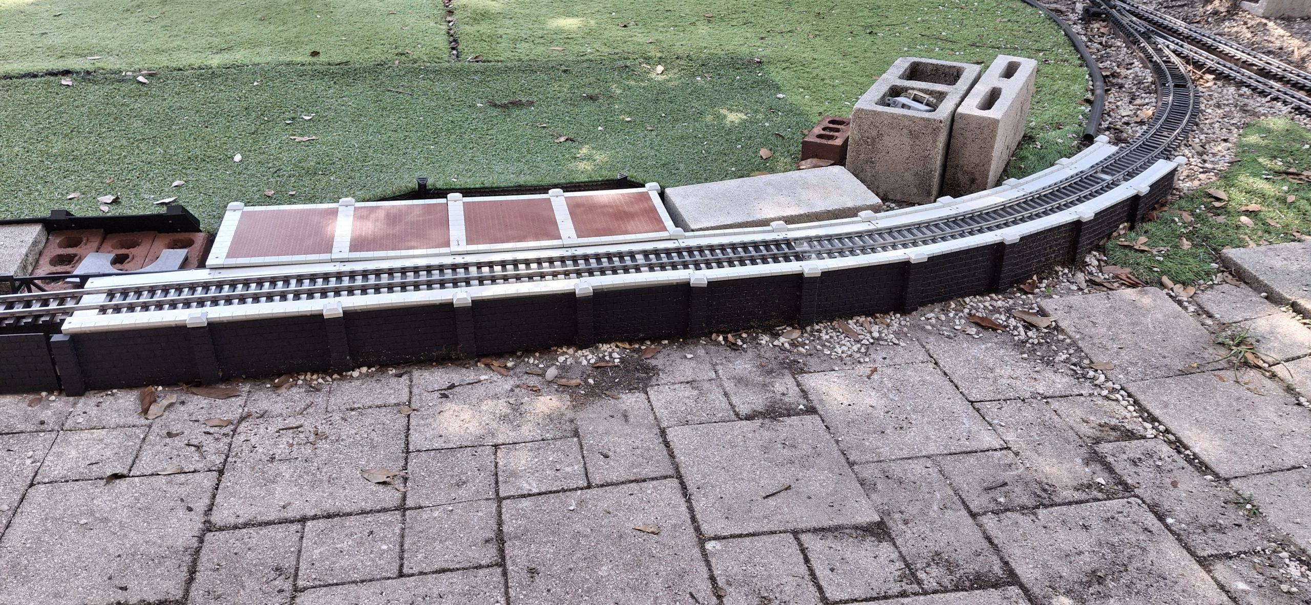
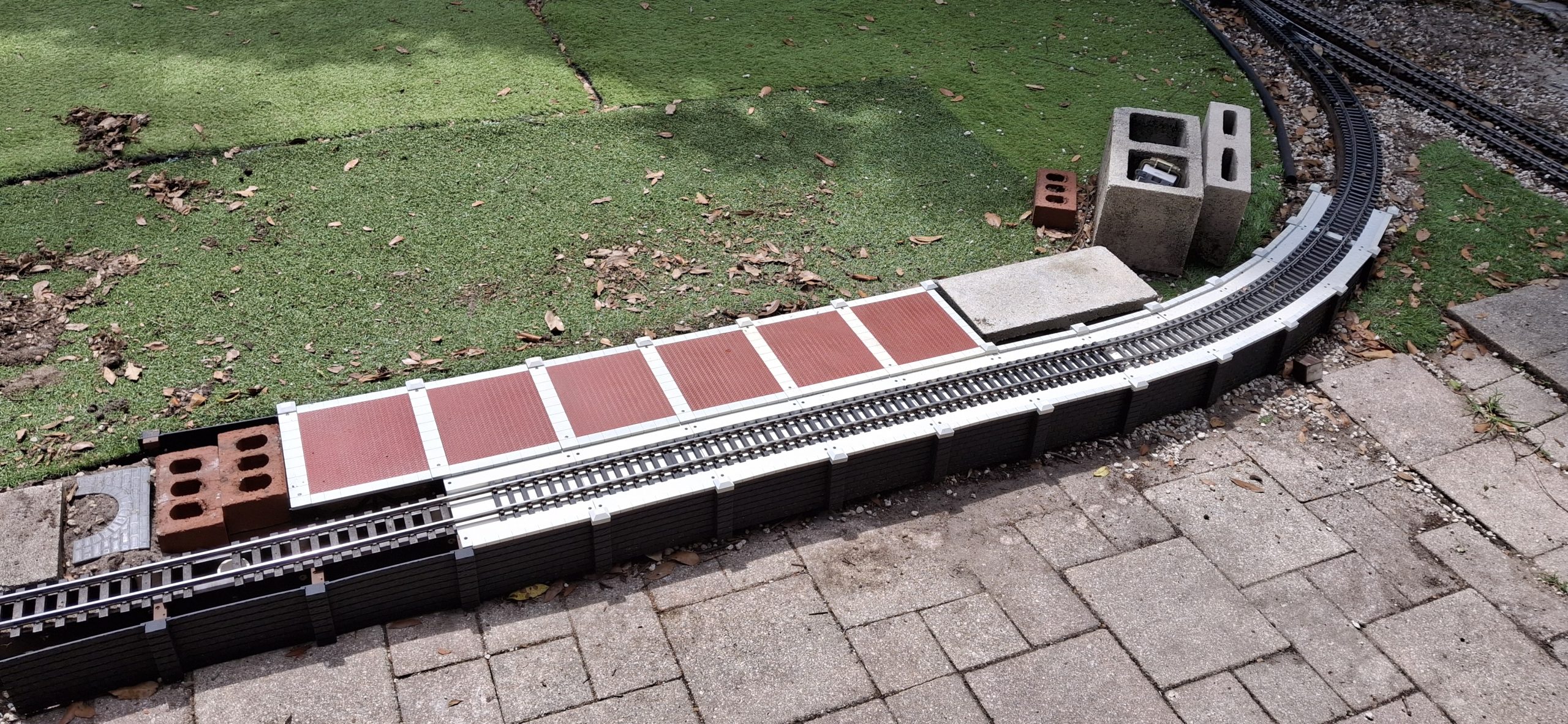
Hopefully the “see through” panels give a better view of how all these 3D printed parts come together to give the illusion of a believable scale model. For me, seeing them slowly come together and become what I’ve always dreamed of seeing is more than satisfying. It truly is a dream come true. The black and gray colors aren’t very realistic, but until the design is finished, it’s good enough.
The design must account for the inside wall changing direction, in this case perpendicular to it. In order to widen the footprint and conceal the half blocks with something that looks like a station platform, we need a different inside transition pillar, plus an additional outside transition pillar to redirect the wall back to the original approach wall direction along the side of the platform.
Unfortunately, because of the dimensions of the half block in that direction, we can’t use the standard 4″x7″ wall connected to all the other pillars. Altogether they add up to 8″ total, too short to wrap around the 7⅝” width of the block. We’ll need a 4″x8″ wall to allow just enough clearance for that block width.
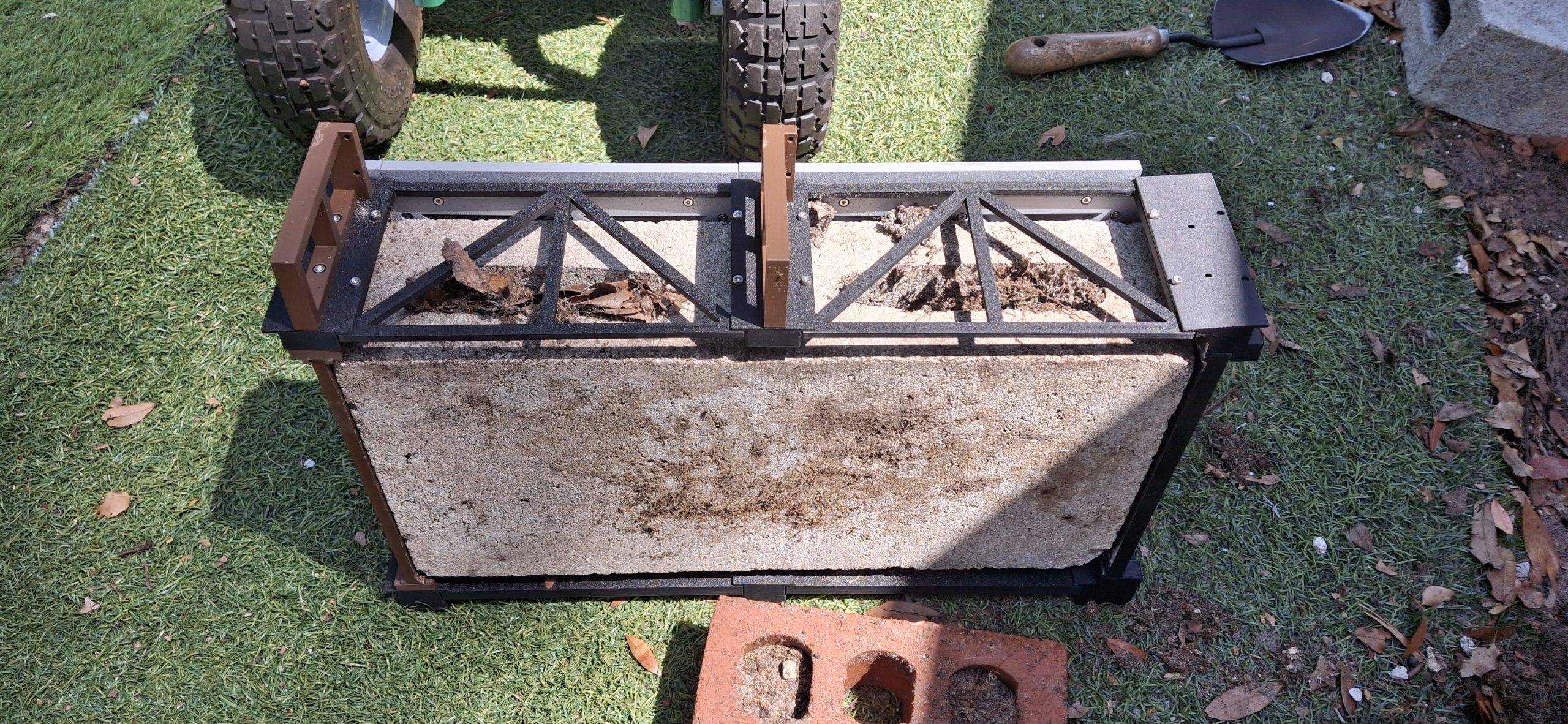
Expanding The Design
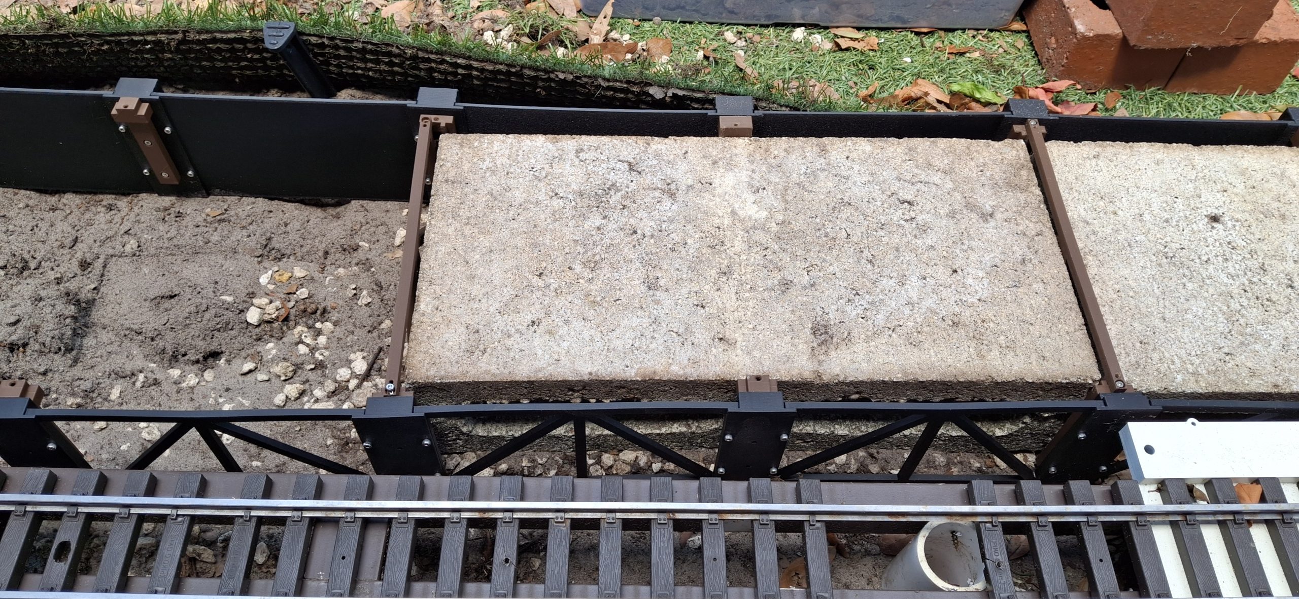
So now instead of two opposing wall pillars separated by the width of the track deck one of those frame mounts will now connect a “hidden wall” section to the opposing cut stone wall. These hidden wall sections will mimic the cut stone wall dimensions along with their own pillars. They connect to a widely separated cut stone wall pillar on the other side of the block every 16″.
Because the block is actually only 15⅝” long, that leaves just ⅜” to work with. The connecting frames between the hidden walls and far cut stone walls are only ¼” thick, leaving barely enough room to spare. It’s a tight, snug fit, but it anchors everything and supports the platform sections. Each section is still only 8″ wide because of 3D printing build volume and “Easy Bake” oven limitations.
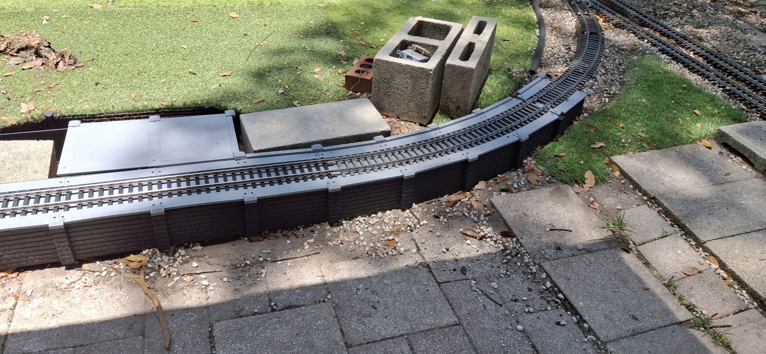
Two platform sections are joined together and fitted 16″ at a time. A “stub” mount for the platform sections is used in place of a connecting frame section where the block length is in the way. This ensures the hidden and far cut stone walls are still rigidly secured together even where a connecting frame member can’t be placed.
Adding The Station Platform
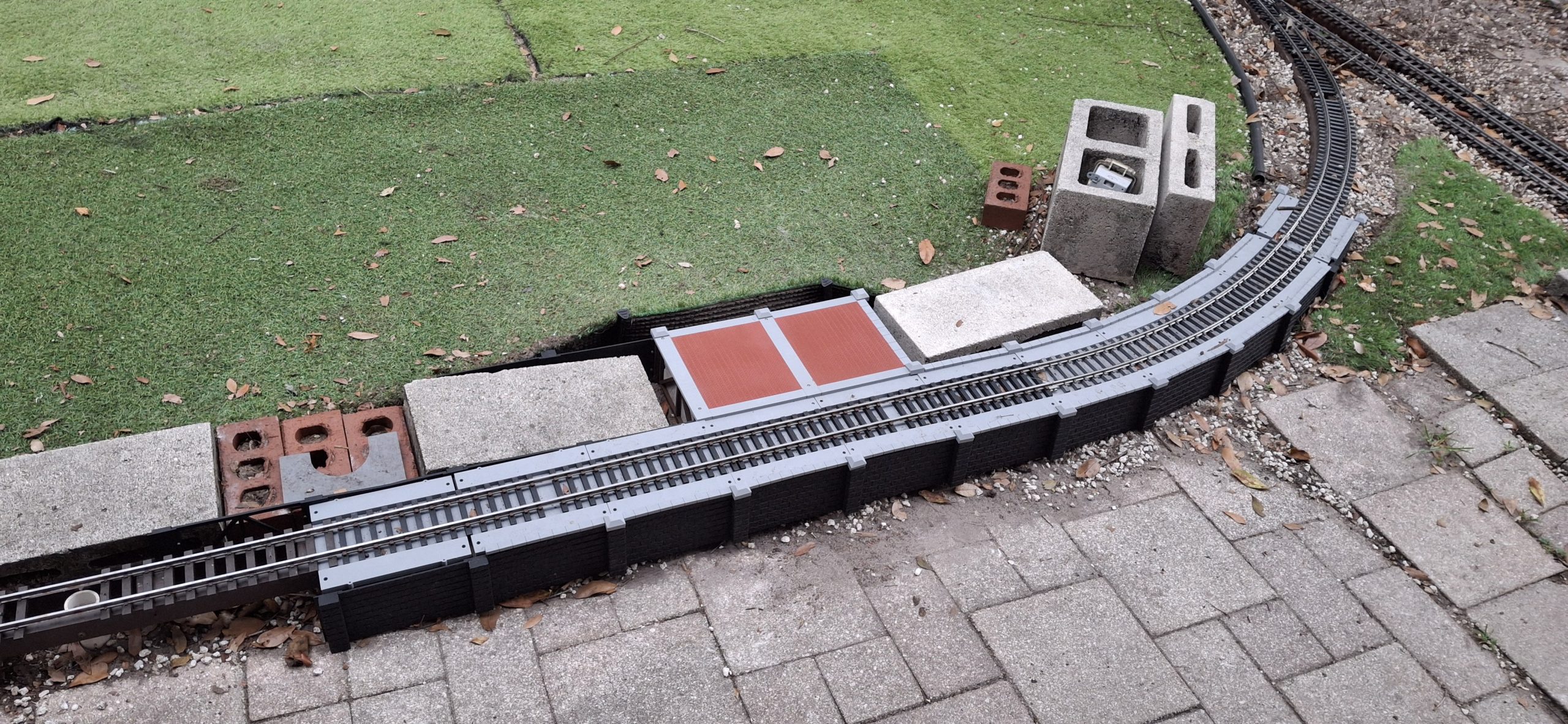
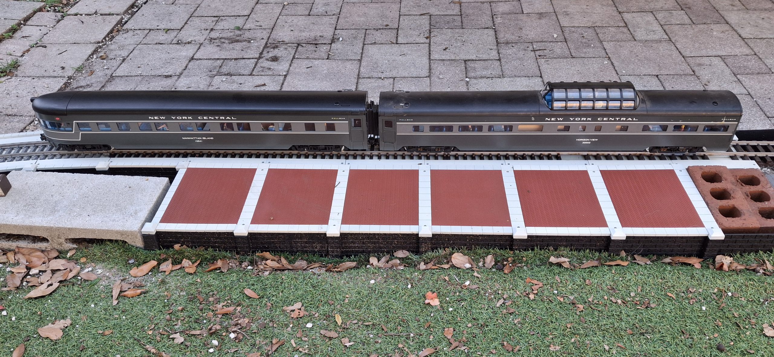
The track deck still mounts to the twist lock frame, but now only one of the capstone strips is needed for the side opposite the platform. The platform design itself takes some thought about how to make a believable scale model that doesn’t have obvious separation “cracks” every 8″. Why not a brick herringbone pattern framed by what appears to be stone blocks?
OpenSCAD to the rescue again! It takes a bit longer than expected to perfect the design, but it’s a believable herringbone pattern, centered about all four sides. It even has mounting holes to attach a support frame that the framing stone block strips will also attach to. Those stone block strip designs are captured in SketchUp along with an imported version of the brick herringbone piece.
To facilitate the modular design concept for adding new sections, the edge of the new platform section will simply slide in beneath a previously mounted section without need for mounting screws. If anything, loosening the existing mounting screws that hold the previous section may be necessary. Then both the old and new platform sections can be tightened down together.
One last “transition” design item is necessary for the first platform section along that 4″x8″ wall. There is absolutely no room for any mounting hardware to fasten the edge of the platform to the wall beneath. The half block butts up against the back of the wall to fit everything in the limited 16″ space. Instead, a set of tabs on the first platform subframe slides into slots on the transition pillars.
Assemble, Rinse, Repeat
After that first transition section from the approach configuration to the platform configuration, it’s simply a matter of adding on another 16″ platform section to the previous. Expanding from first platform section to the third doesn’t happen overnight, but it doesn’t take long since I’m printing most of the parts while redesigning the ones that aren’t working as expected.
The only limiting factor on the platform expansion is how long it takes to 3D print all the parts, anneal, paint, and assemble them into the next 16″ section. It takes a lot of parts! Four each retaining walls and pillars, two each hidden walls and pillars, twist lock frames, hidden frames, platform decks, platform subframes, deck border stone sets, track decks, and track deck capstones.
I’ve tried to capture the estimated print times of all the parts when slicing them. Let’s see how well I did and whether I can add them all up for a rough estimate of print time. Add at least another hour to anneal each print, although the last part printed can be annealed while the next is printing. Then add painting the annealed parts and assembly time. It all adds up. But progress is progress.
Color Considerations
Our color palette in HT-PLA is fairly limited, even more so than PLA. Just the basic colors. While the capstones could have been printed in white, the single ACE cabinet only has four slots it and would mean having to constantly swap between white and one of the other four colors, namely black, brown, gray, and red.
Gray was chosen with the idea that the red is too bright for bricks and would need painted brick red anyway. The track deck and capstones can be painted concrete and light stone colors. The black cut stone walls don’t need any paint, but should probably have some sort of UV protection painting the other parts offers, and perhaps a wash with a lighter color to bring out the details.
After an extensive Google search for matches to the Model Master “Aged Concrete” color from my HO scale days, satin Dover White and satin Ivory are chosen for the concrete and light stone colors. At first, they look like they’re same color, but later spray paint batches aren’t as close. Natural variations in stone colors? Plausible explanation if anyone asks. LOL.
Brick red is brick red. Alright, there are variations to be sure. I even made brick color selectable for OpenSCAD, brick red or creme (beige). I’ve seen many modelers design and print painting masks to expose “random” bricks and paint them slightly different colors to mimic the natural color variations. I know I’m a rivet counter, but I haven’t made it to that level of obsession to detail (yet).
What’s Left?
The station platform is slowly expanding. The original platform was 16′ long. Now it extends beyond the end of the patio, so approaching 20′ maybe? So far we’re about half way done, right at the end of that first 10′ stretch of flex track. We can add another 16″ section every couple of days in production mode, pretty much 3D printing parts 24/7.
I’ll wake up in the middle of the night and kick off another if the previous print’s finished. Sometimes I’m a sound sleeper though. But it only delays the inevitable, kicking off of the next print once I’m able to. So far I’ve only screwed up twice trying to go faster than I should have.
First was forgetting to put the PEI sheet back in the printer and frantically killing the print before it could cause more damage. I’m missing a small chunk of the magnetic material that holds the PEI sheet to the build plate after that little fubar. Kicking off another print while the previous one was still sitting in there on the PEI sheet was another. “Why’s it making that clunking noise? OH SHIT!”
I can laugh about it now, but it certainly wasn’t all that funny at the time! Getting back to what’s next, the end panel of the platform still needs designed. Similar to the transition to platform configuration, now we get to the terminate the platform and need to finish it off with walls and pillars that connect the retaining wall together. We won’t have the luxury of tabs and slots this time!
Future Reference
Observations for future reference – overlaying two stone textures atop one another gives a much more realistic looking stone face, but not sure how to “add them together” in a usable fashion. Maybe someday. This is mainly a note to my future self when revisiting the stone texture design. It’s strange that when I rendered the imported stone modules this time it didn’t error out. WTF?
I’ll update this post periodically with progress toward completing the station platform. For now, I just want to get this posted. I’ve been so busy doing so many things it seems impossible to both do and post. I haven’t looked at editing a video in months. Everything takes time and right now the focus is getting the trains running and restoring the previous “luster and glory” of the Barkyard RR.
I have to say I’m pleased as punch with the outcome of this project! It’s been a long time getting here, but it’s worth the wait for the result! All the projects I put on hold are slowly coming out of mothballs. All the things I’ve put off for so long are finally coming to fruition.
In the past I worried about prioritizing things that needed done first. Anymore, I just do what’s staring me in the face, then ask myself, “What’s next?” and just do it. I kind of have to since I do things like buy a bunch of clearance Aristo-craft stuff that’s not in the best condition, then have to design and 3D print replacements for all the broken and missing parts while juggling 19 other projects.
So far so good, but that’s another story.
Disclaimer – Not Sponsored
I should mention that the Barkyard is not sponsored by AnyCubic, PolyMaker, Elegoo, Sunlu, or any of the host of other manufacturers of 3D printers and filament or any other entities, like Harbor Freight. I don’t think they’d care much for my nicknames for them anyway, like Horrible Freight, Hazard Fraught, etc. No freebies or evaluation promotions here. This is all paid for out of pocket.
Question? Concerns? Leave A Comment!
If you’re interested in obtaining the STL files to print your own block walls, leave us a comment and we’ll be happy to provide them to you. Also, if you have any other questions or concerns, please feel free to comment on this post. In any case, you’ll need to create a user account to do so. We don’t use any personal information for marketing or to spam you (see our privacy policy). You’ll receive a verification email. Reply to the link provided to verify your email address. It’s all automatic. No waiting on moderator approval! No spamming your inbox with useless advertisements and “Special Offers”. None of that nonsense. We do it this way to prevent bots and spammers from detracting from your experience.
More to come. Stay tuned!