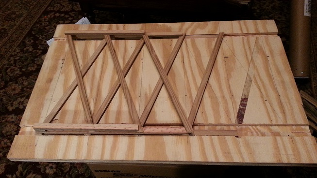
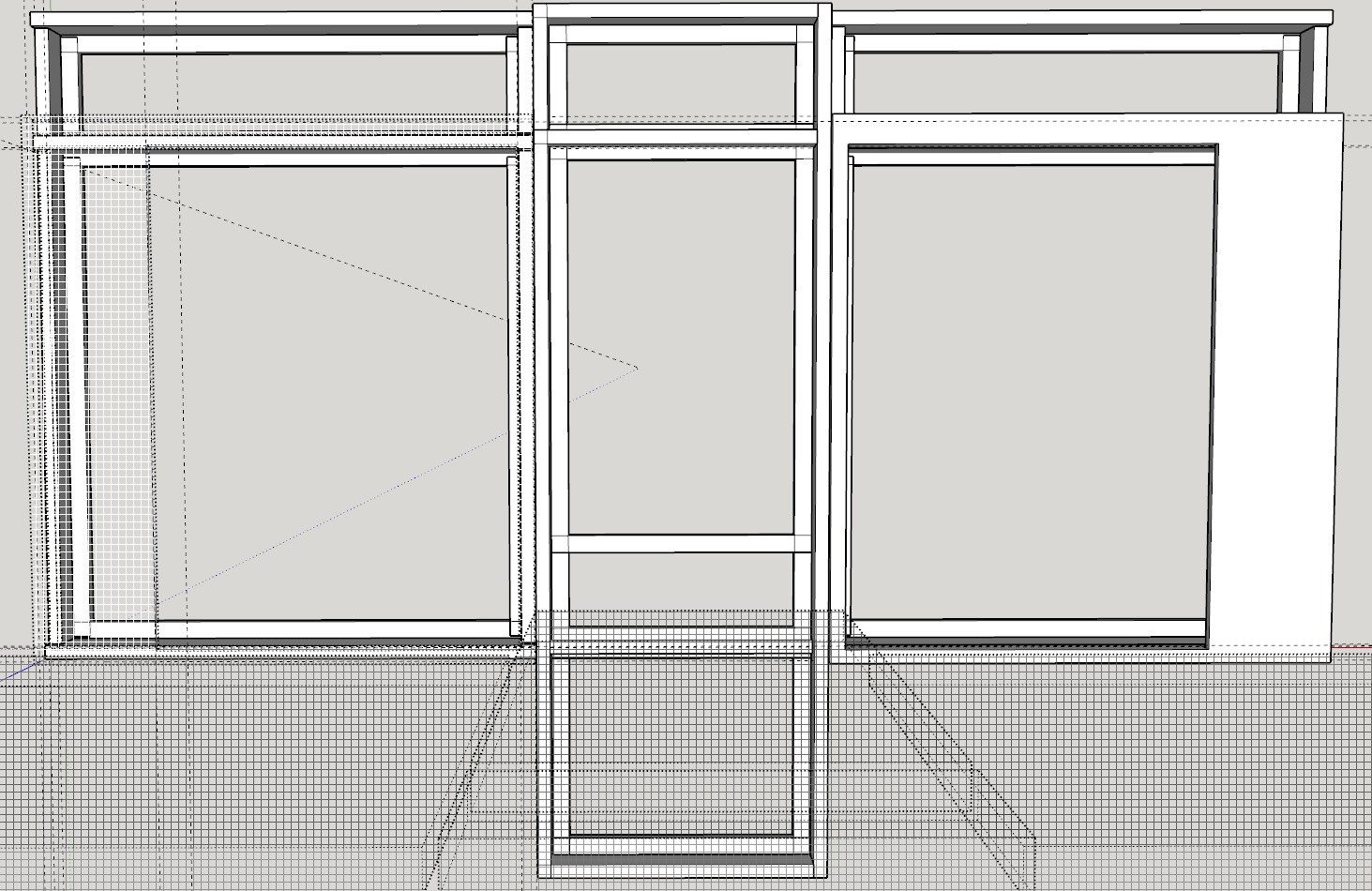
The Featured Image above shows the results of our efforts so far. Below is what we started with… Three very rough castings obviously covering concrete blocks.

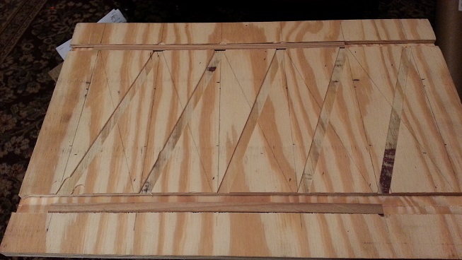
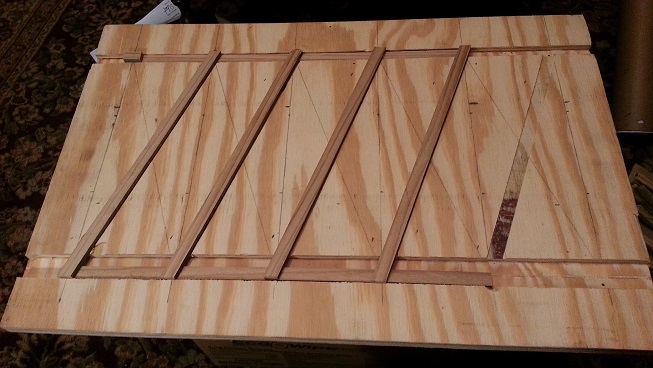
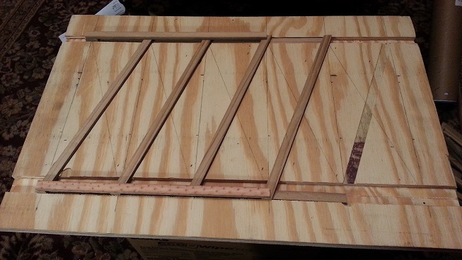
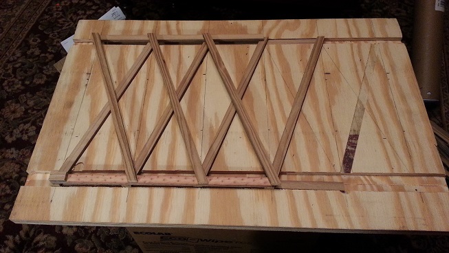
I’m designing the downtown market display case view blocks to conceal the edges of the concrete block on the first floor. I don’t really have a specific example of a building to model in mind, just a vague recollection from my childhood of what buildings looked like.
The building itself is based on some of the HO kits I assembled ages ago. These kits all start with the same narrow faced three story building, but add different details, like a funeral parlor or a five and dime. The bottom floor is always different, but the upper floors have similar window frames and clear glazing. Even brick patterned blanks are supplied to close off openings if desired.
I’ve already designed the window frames, experimenting with different glazing. With nothing to conceal the concrete block behind, it was obvious something was needed. First I cut some opaque black ABS to fit behind the frames. It definitely blocks the view! But unfortunately, it also means lighting is out of the question!

In the Featured Image, the building on the right shows the different between nothing behind and black ABS. The building in the middle show what the translucent green looks like compared to the ABS. None of the building have the display case view block installed yet. See the end of the post for a view of all everything populated.
I’m also trying out the “see through” dark green filament I bought, as a stand in for the soda glass of the day, or perhaps tinted glass on automobiles. Hopefully. It’s a little dark for the window glazing, but looks better than the clear filament, which is anything but clear. Translucent perhaps, but it just looks too white and opaque.
When I had just the black ABS cutouts behind the frames with no glazing it looked better than the translucent “clear”. And now the new translucent green looks better than the ABS view block. I need to experiment with back lighting and see if it still looks as good.
Even my “venetian blind” modification doesn’t look like anything but opaque white! It works only slightly better with the translucent green. Perhaps once it’s backlit it will look like blinds covering the inside of the windows. We shall see…

Iterations and Alterations
Just as the window frames underwent a number of modifications, so did the design, fitment, and assembly of the display cases. The original casting is meant to have two display cases behind large, transparent windows, one on either side of the entrance which is placed in the middle between the two.
The entrance represents a metal framed door with a transom above, typical of the era. For variety, the transom can be fitted with a more modern air conditioner. For now, I’ll concentrate on getting something there first. Details can be added later.
The entrance will be assembled from the three pieces previously described, due to limitations of 3D printing. Overhangs are a no-no. They can be overcome using supports, but it’s more work to clean up the traces left behind by them. The tradeoff is gluing the pieces together, but how to glue them together? We need something to glue together first…
Printing Storefronts
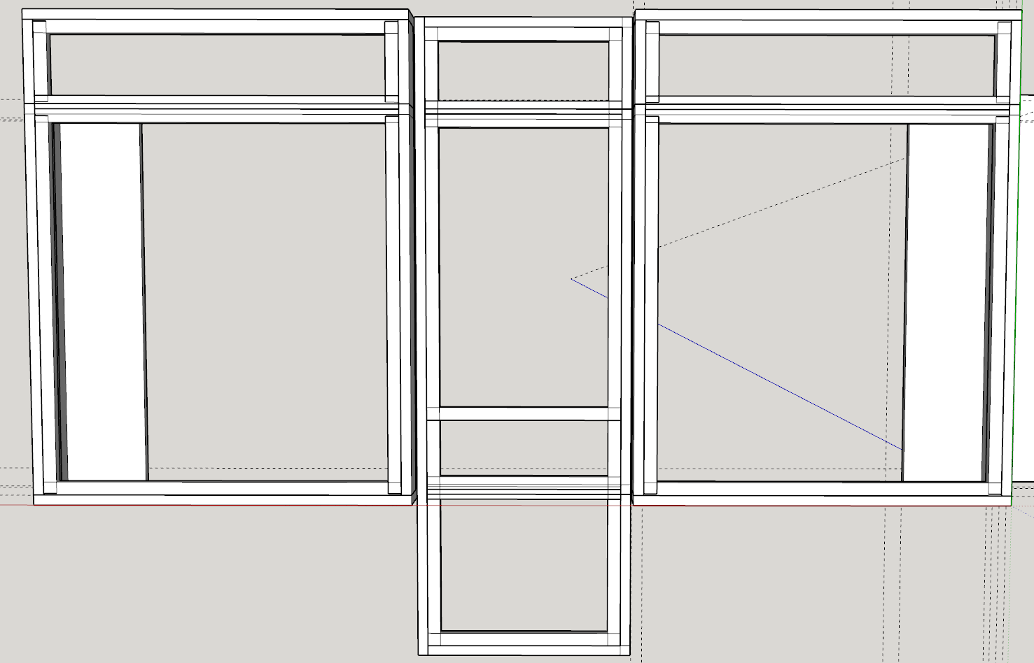
The beauty of the design’s symmetry is both display windows are identical, allowing both sides to remain a single, interchangeable assembly. Together with the door assembly, they can fill the void of the street level opening meant for them.
I recently purchased an assortment of “metal” filaments for the 3D printer. I’m hoping the silver looks enough like an aluminum frame to pass as metal. Even just the standard silver (gray) filament will look enough like an oxidized galvanized finish, so it’s not really a problem if it doesn’t. It still looks better than nothing!
I already printed window frames using the plain silver gray filament, so I print a set using the silver metal filament first. The showcase frames have a place for colored insets above both the door and windows, as well as the bottom kick panel of the door.
Rather than print the insets in the gray color, I decide to use red to make it “pop”. I refrained from printing more window frames in red for fear it would be overpowering against the brick red of the casting. The gray will work well enough for now.
But the real test will be the copper color! I’m thinking about using it for the cream colored brick building, together with brown inset panels, to really make it “pop”! I can’t wait to try it, but wait I’ll have to.
Assembling The Storefronts
My first prints of everything need revision! The frames don’t fit together the way I want them to without a redesign. Even then, the next version still needed some judicious filing, but that left the fit too loose. Even the insets don’t fit!
I quickly learned I need to leave about 0.010″ clearance between pieces if I want an exact fit, and by exact I mean almost an interference fit. I reprinted the insets and this time they almost “snapped” in place. I say almost because they are just loose enough to find their way back out on their own.
So not only do the frame pieces need to be joined together, the insets will need something to retain them in place as well.
Plastic Welding or Plastic Cement?
Even though we’re talking about adding details to cement blocks, the plastic cement we’re talking about is like styrene model cement, the kind that chemically dissolves the plastic together to create one solid piece once it flashes off.
I’m not sure what glue works on PLA. Acetone works for ABS, and supposedly for PLA too. A quick test says I don’t know what they’re smoking, but it has no effect. Model glue does a little better, but still leaves a lot to be desired. That’s not working. Next. I read good reviews about using a plastic welder, so I decided to buy one and try it.
The ones most recommended double as a child’s “toy”, but I’m not sure what parents would hand their grade schooler a hot melt glue gun these days. That’s basically what it is, except it uses plastic filament for 3D printing instead of glue sticks. And at 210°C (410°F) for PLA, it’s about twice as hot. May as well hand your kid a soldering iron at that point!
When it arrived, my first attempt at plastic welding two parts together worked, but with mixed results. It effectively joins the parts together, but the joint isn’t very strong. And like welding metal, it leaves a visible bead of material at the joint. Let’s just say it doesn’t look like a stack of dimes…
After assembling the first storefront, I am thoroughly discouraged by the results. Even though I was able to keep the ugly weld bead hidden from sight, it doesn’t hold the assembly together long enough to press it into the opening in the casting, quickly snapping apart!
My assumption that it physically heated both parts to welding temperature while adding filler material was not a good one. It basically melts only the filler material. There is no molten “puddle” of material like metal welding.
PLA Cement a.k.a. Dichloromethane
A bit more research finds that dichloromethane is the solvent I’m looking for… a.k.a. chloroform. Great. Now where do I get that? Even after all the “Does this rag smell like chloroform?” jokes, it’s surprising how many products use it as the main ingredient! Methylene chloride was widely used as a paint stripper, now both are banned banned, replaced by a far less effective ingredients.
Just be bopping down to the paint department at the local big box store sounded like a good idea at the time, but they no longer carry methylene chloride, let alone in those gallon tins. Guess I should call myself lucky to still be able to buy acetone by the gallon.
What’s amazing to me is there are still many suppliers online. I went with “WeldOn” products, no affiliation. It’s expensive for just a pint can, but they deliver to my door! There are a number of different “acrylic adhesives” in their lineup.
I tried their #16 first, which worked incredibly well on plexiglass, but is really thick. Too thick to seep into the crevices between the parts via capillary action. It works, but has to be brushed on, wasting a lot of it in the process, kind of like using a firehose to water the flowers.
I ordered their #3 and #4 variations next. They are definitely liquid, thin enough to flow into the tiniest of crevices. The #3 is quick acting and the #4 has a longer working time. Both flow easily into the joints. All three should be used only in a well ventilated area or asphyxiation could result.
Along those lines, this stuff needs to be tightly sealed so it won’t totally evaporate away. Both the #3 and #4 came sealed in heavy duty ziploc bags over the sealed metal lid of the metal can! The first time I used it, I found out the hard way how quickly this stuff evaporates!
Learning the Ropes
The small squeeze bottles with attached hypodermic needle that came with them have a twist-lock “cap” of sorts to protect the tip. More like to protect you from stabbing yourself with it, but even that wasn’t enough to seal it. I had a third of the squeeze bottle worth of #3 left in the bottom when I went to bed. It was all but gone by morning!
From now on, any leftover gets immediate placed back in the can and then sealed in the ziploc. I also found the needle to be prone to clogging with the dissolved plastic after a short amount of use. Squeezing it to blow out the clog either doesn’t work, or if it does, floods the work pieces with solvent.
I found a better way to dissolve the clog was just to hold the squeeze bottle upside down until the solvent itself dissolves the clog. It doesn’t take long and it’s fairly obvious when the clog is gone. Hard to ignore the solvent that starts streaming out again. After the first few uses and it taking forever just to get enough sucked up into the squeeze bottle through that small needle, I decided to find some larger versions.
I now have so many of them, I can’t give them away, but the thought was they would fill quickly and I could use them to quickly transfer the contents into the hypo bottle. They came with an attached silicon cap to cover the larger, blunt tip, but even they don’t seal well enough to leave any leftovers inside for more than a day or so. I’ve gotten in the habit of pulling out a little solvent at a time, using what I need, then returning what’s left to the can when finished.
The Test of Time
So long story short, after a few false starts, we finally managed to get those three buildings looking more like a downtown business than a concrete block. They still need modifications to continue to serve us as downtown marketplace buildings though. The elements were not kind to the PLA plastic, as seen in the picture below.

I should have used some adhesive caulk to hold the windows in place too. Slowly but surely the dogs managed to knock out every single window. It got to the point that every time I went out to work on the Barkyard, I had to pick up a couple more windows, just laying in the street or on the ground. I started a collection of them in the garage so as not to lose them.
Next go round I’ll need to paint the plastic with UV resistant paint, maybe even just a clear top coat, but an opaque color will provide far more protection from the sun than clear coat ever could. At some point I really need to get some display cases put behind there though.
I finally removed the ground floor display cases and stashed them away too. Ann says it looks like a ghost town. So we’re thinking of making more castings, enough to build an entire ghost town downtown for Halloween! I’ll need to accelerate my efforts to add lighting and other “spooky” effects, but it should prove entertaining regardless.