
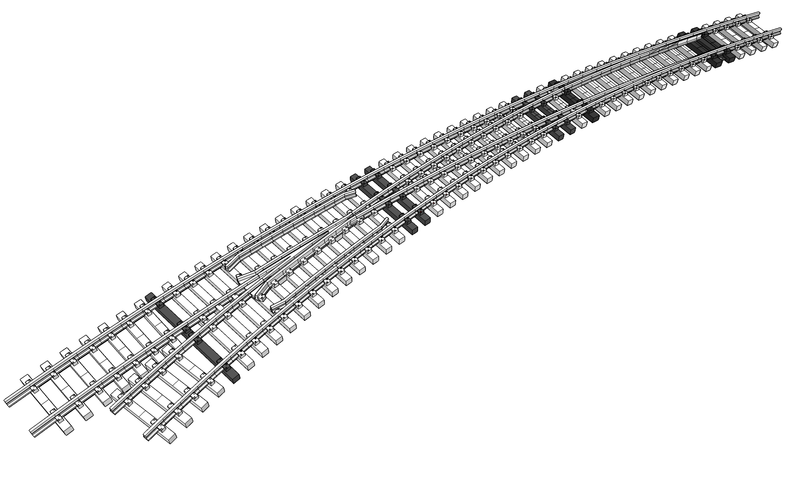
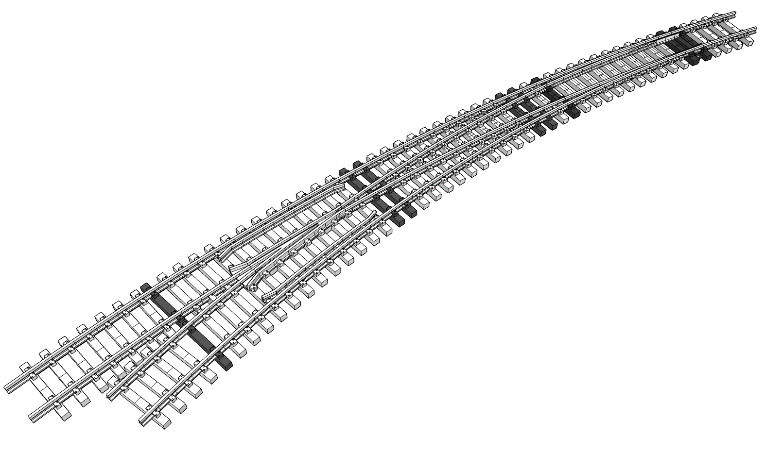
Welcome back! This is the second part of the curved turnout series. If you haven’t seen the original post yet, you may want to start there first. A good part of this discussion relies on topics covered there already. So where did we leave off? That’s right, the new spool of filament wasn’t the best. The brittle nature of the filament is causing problems with prototype fitment and development.
Its brittleness coupled with a lack of complete support removal is a sure way to snap the foot clamps right off when attempting to test fit the rail. So one more refinement will be to back them off another 10 thousandths as well as raise them all by 10 thousandths. It’s also a vote to just reprint those other ties strips using the other design refinements so far.
But that’s not as easy as changing one model to fix all of them like it was with the diverging route ties. Every one of those remaining switch ties is unique. There are 48 of them altogether. This is where SCAD or other parametric CAD applications shine. Need to nudge everything in the same direction? Simply update that parameter and rebuild the model.
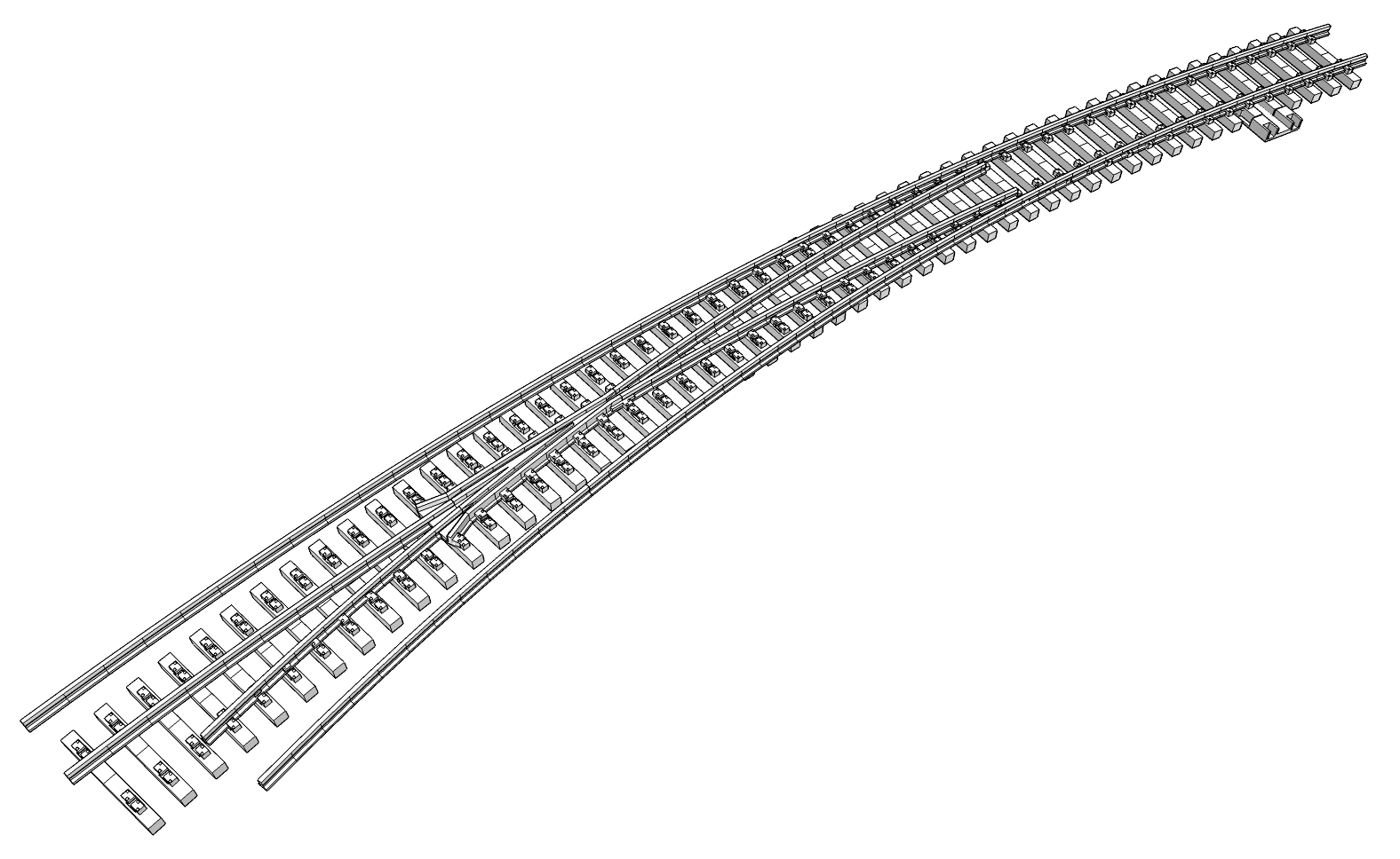
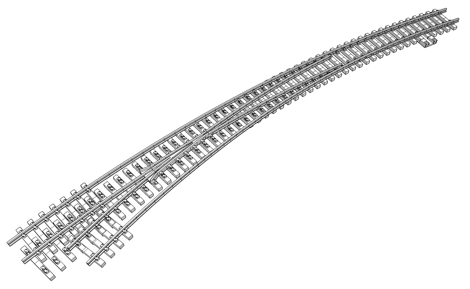
For example, to increase the distance between the tie and foot clamp, it’s a simple change to increase that parameter and rebuild. Not so much with SketchUp. It’s all tedious, time consuming manual effort per clamp per tie. I suppose I could have used a component to model the rail foot clamps, where changing it once would affect all instances, but it wouldn’t account for other factors.
Why Not FreeCAD?
As much as I’d like to put this design in FreeCAD, I keep falling into the speed trap. The speed of implementation trap that is. I already know how to do just about everything in SketchUp and how to workaround things it doesn’t handle gracefully. For me with FreeCAD, it’s at least a Google search, if not another lengthy tutorial video just to learn the basics.
There may come a day I don’t feel the time crunch, but today is not that day. I need to put this new printer through its paces to verify everything is working, and working the way it should. Like most warranties, they’re for a limited time only, plus I want to get rid of the shipping box I’ve been saving in case it needs sent back. The sooner the better.
What new printer? It’s an AnyCubic Kobra S1 Max Combo. It arrived about a month ago and I’ve been waiting for it to get here since I ordered it around Thanksgiving last year (2025). It has a build volume of 350mm x 350mm x 350mm (13.77″ x 13.77″ x 13.77″) and can print up to four colors with the single ACE cabinet version I bought. With more ACE cabinets, it can print up to 16 colors.
All that being said, now I’m paying the time penalty for using SketchUp, which means having to revisit every single one of those rail foot clamps, adjusting them one by one, for every tie. I marked the ones I had to adjust from the initial 17′ diameter tie placement and stretched to fit the 14′ and 20′ diameters. Thankfully I also marked the ones I had to adjust for interference.
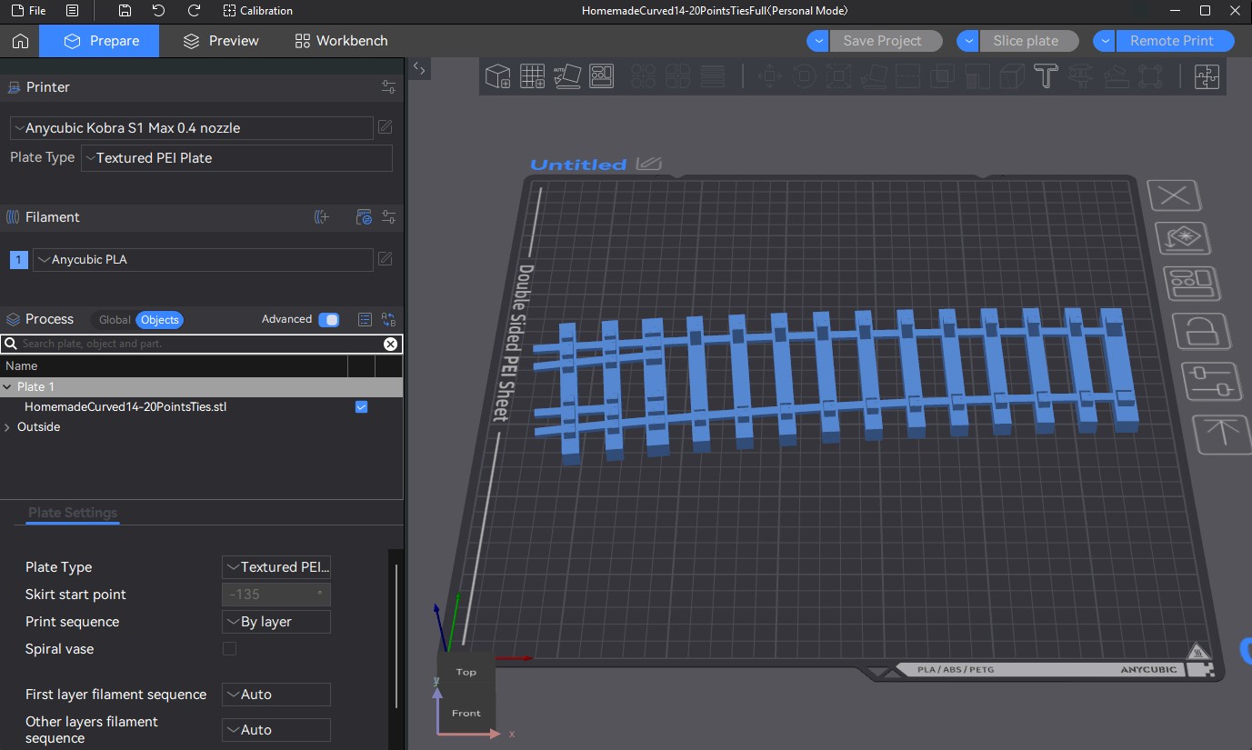

Moving Forward
Now the question is whether to just save the current version as a prototype fallback and make the changes to a new version or press ahead blindly. The latter is what I got without even thinking about it. Now I’ll find myself unable to rewind to a previous version later. SketchUp is unforgiving when backtracking to a mistake made many operations ago.
On the plus side, reprinting all those tie strips means I don’t have to finish cleaning up all the rest of those supports! There are few more things I’d like address while I’m at it, like how to mount the frog to the tie strip. The screw placement and openings for the mounting hardware need laid out. If I print things in the same order, I’ll have time for that while the others print.
Another thing I need to look at is using spiral vs. rectilinear top surface texture when slicing to 3D print. The former leaves a pattern that resembles wood grain and the spike head details are visible, but the “diagonal corner” is unrealistic. The latter is smoother, but those spike details are missing. There may be a way to tell the slicer not to rotate 45°. If there is, I certainly haven’t found it (yet).
This will sound like nonsense to folks who aren’t familiar with 3D printing, slicing in particular. Hopefully this isn’t too basic, but 3D printers do their work a layer at a time, building each successive layer on top of the previous one. The slicer effectively slices a 3D model into layers, hence the name slicer. It tells the printer what each layer looks like and how to print them using GCode format.
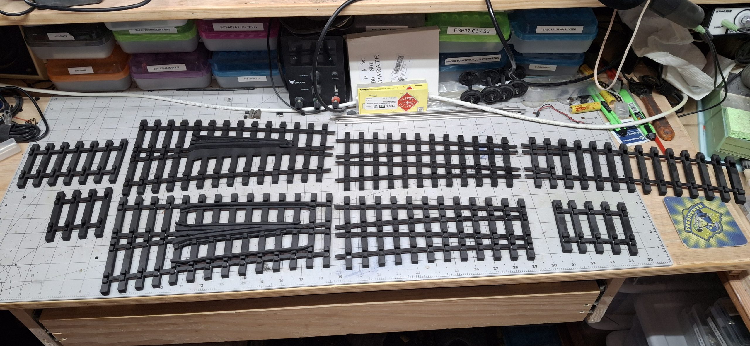
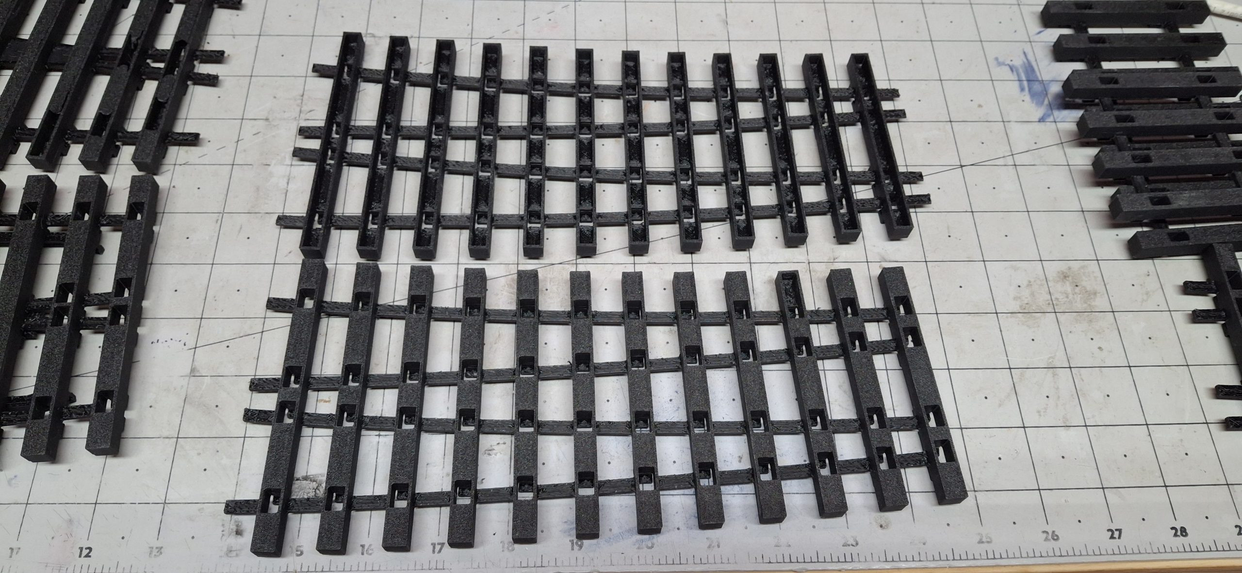
The Slow Grind Of Rework
Reworking the rest of those tie designs is a chore. A chore I’m not looking forward to. Hours and hours of zooming in on each an every foot clamp on each and every tie for days on end. Thankfully my motivation hasn’t failed me, printing the fruits of my labor while pressing on to finish the next section. Unfortunately it’s finished printing the previous section long before the next is ready.
I knock off “early” the first night at 11:00 PM, knowing the guys will be here bright and early the next morning to put up the new fence around the Barkyard. But that’s a different story for another time. By the end of the second day I finally have all the parts printed again, including the frog, now with mounting holes and wing rails.
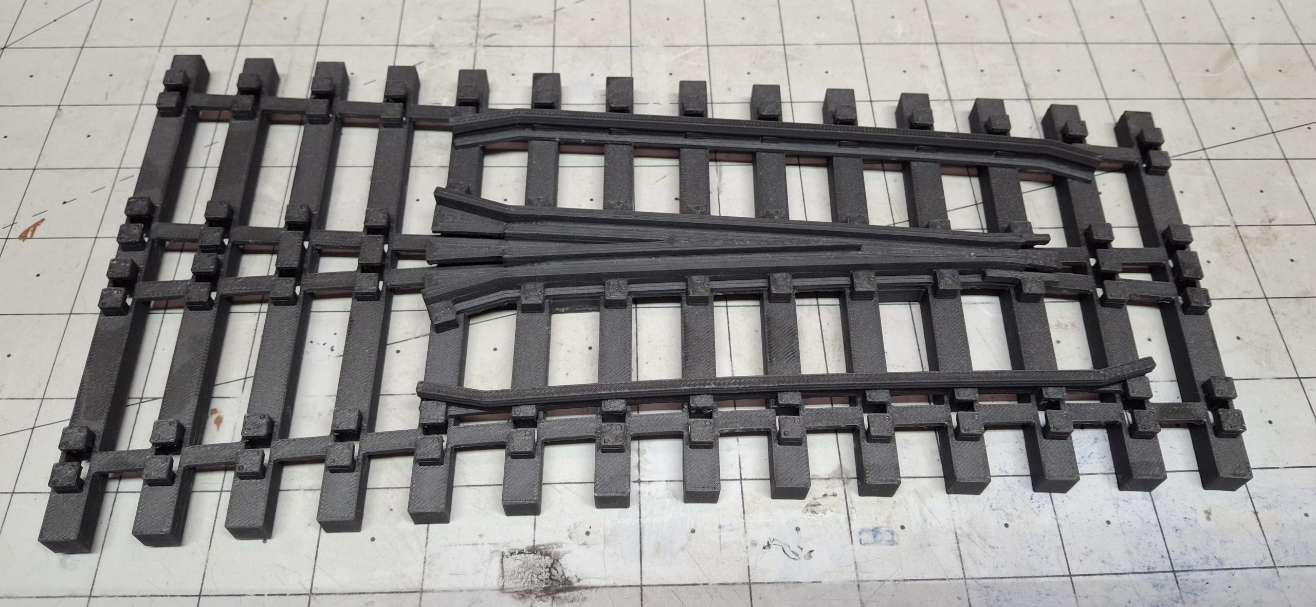
Speaking of the frog, that “SketchUp is unforgiving when backtracking to a mistake made many operations ago” was spot on. I had already reworked the hold downs on one side, effectively half the frog modified, when it became apparent there was a major mistake made many operations ago. Sometimes this free program is worth exactly what I paid for it… Nothing.
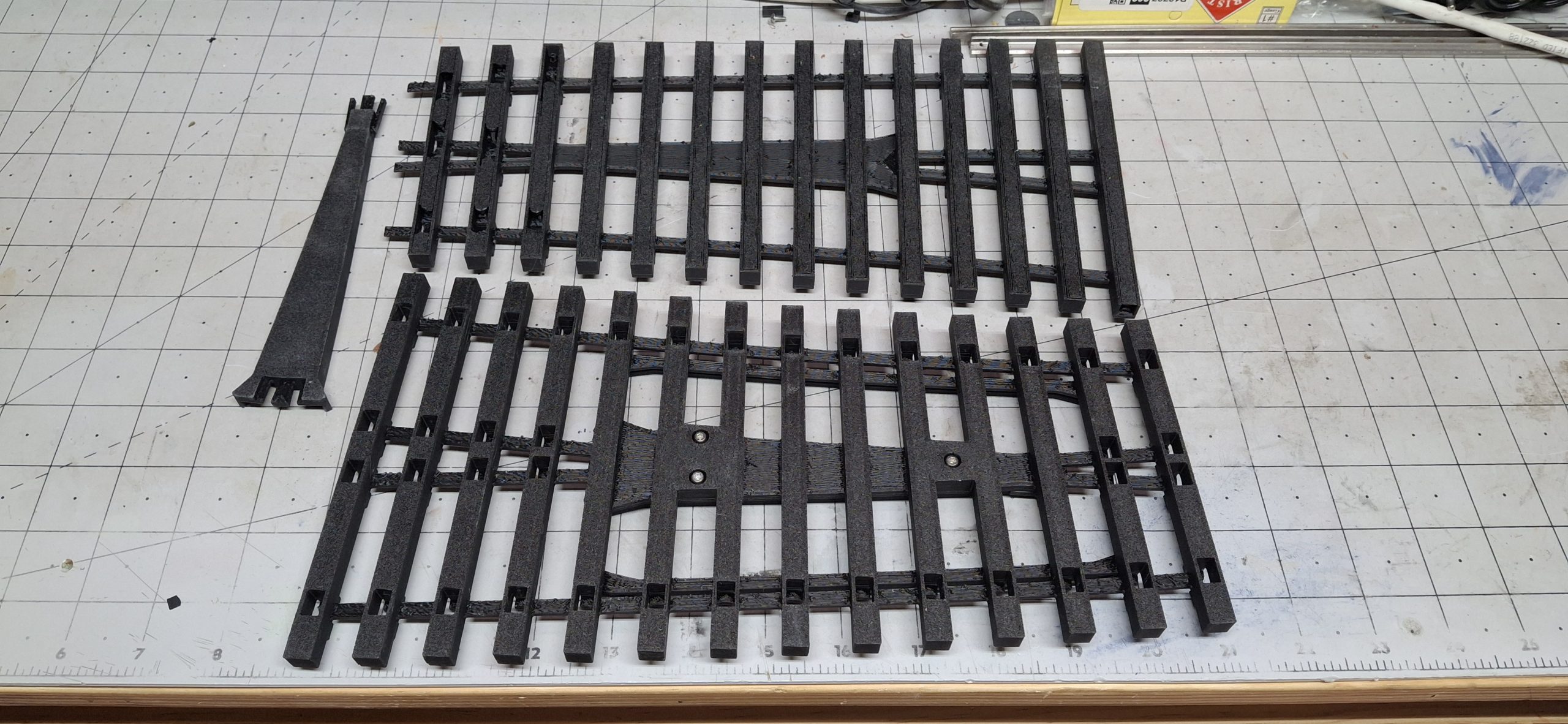
Feeling Froggy
So as not to lose anything I had done so far, I copied the frog to another drawing and began the tedious “Undo” process back to the single misstep that caused the problem. This is where the history of operations is so valuable in other applications like FreeCAD. Made an error? Just go back and fix it and the change propagates forward without further impact.
Not SketchUp. Rewind then redo EVERYTHING since the mistake. Thankfully I caught it with only half the frog reworked. After that adventure, I was very careful to check my work frequently, especially when adding the guard rails to the frog tie strip section. But that’s the last design to finish for now and it’s printing, with an estimated 6 hours and 39 minutes to go.
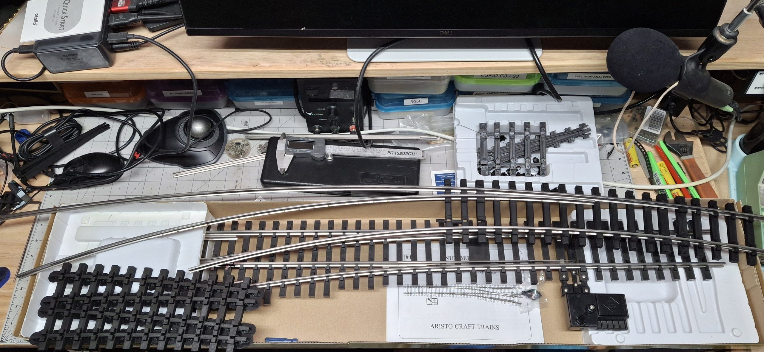
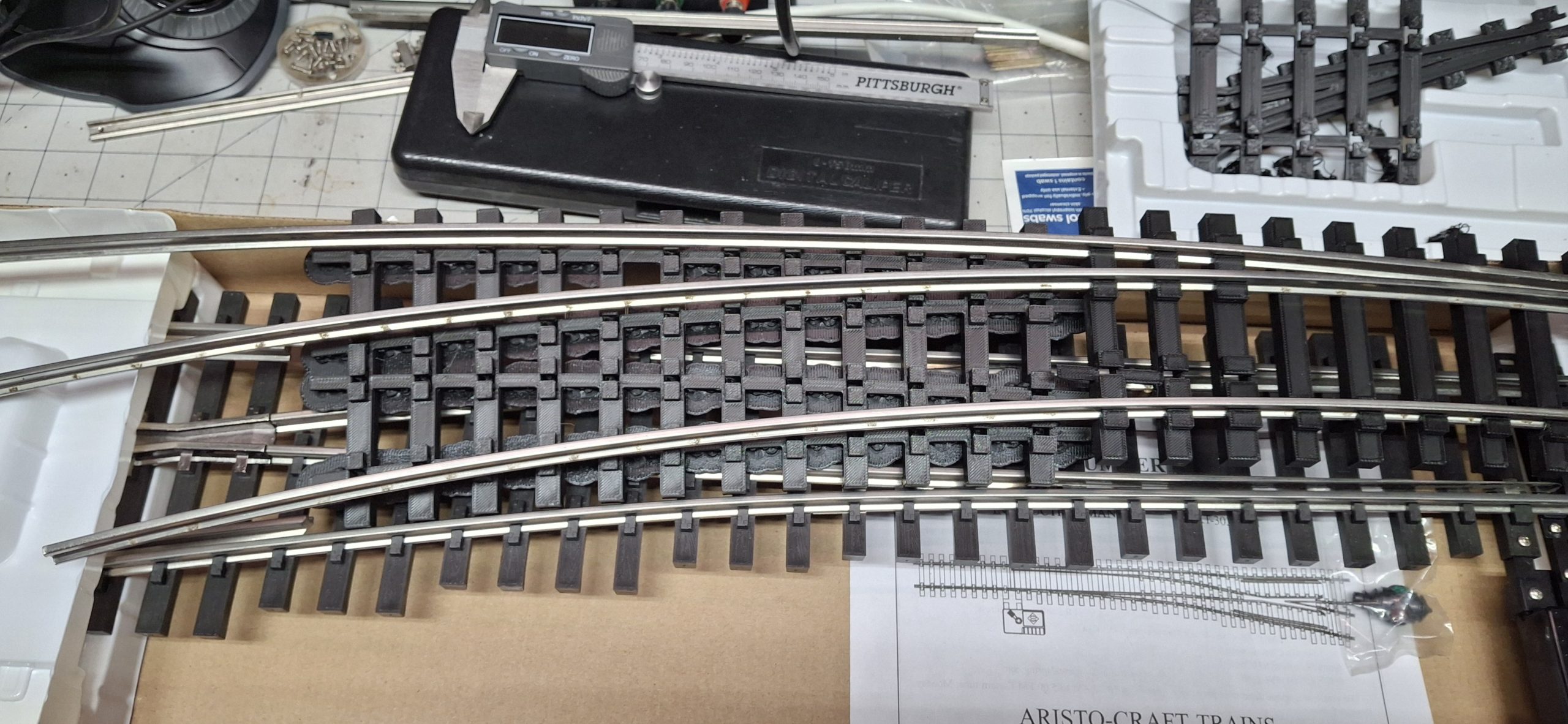
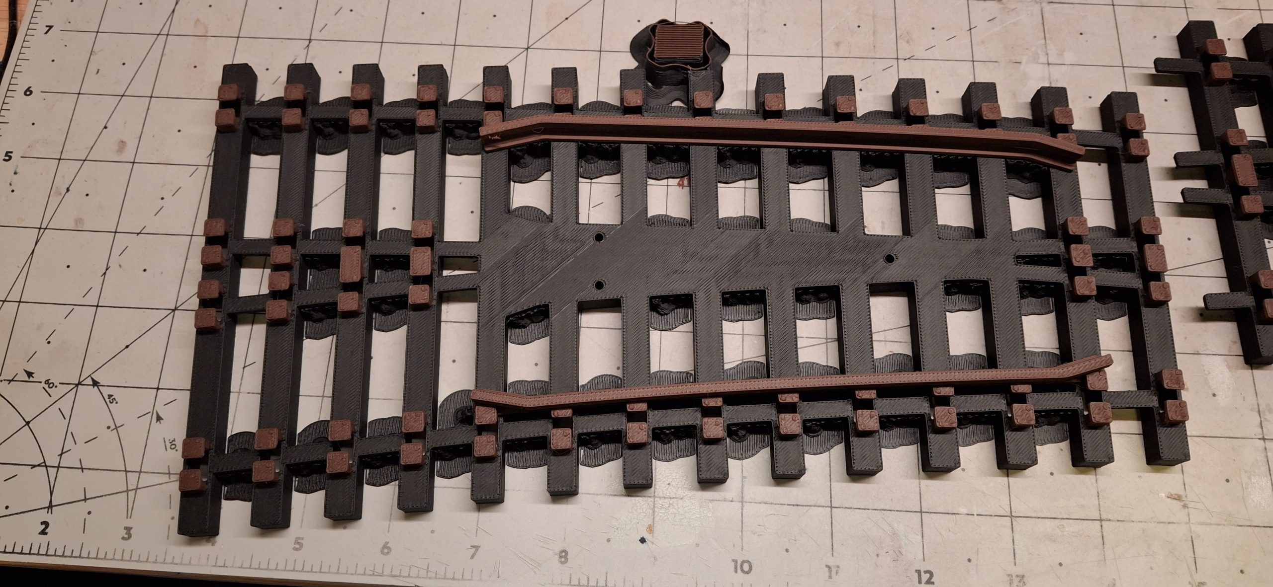
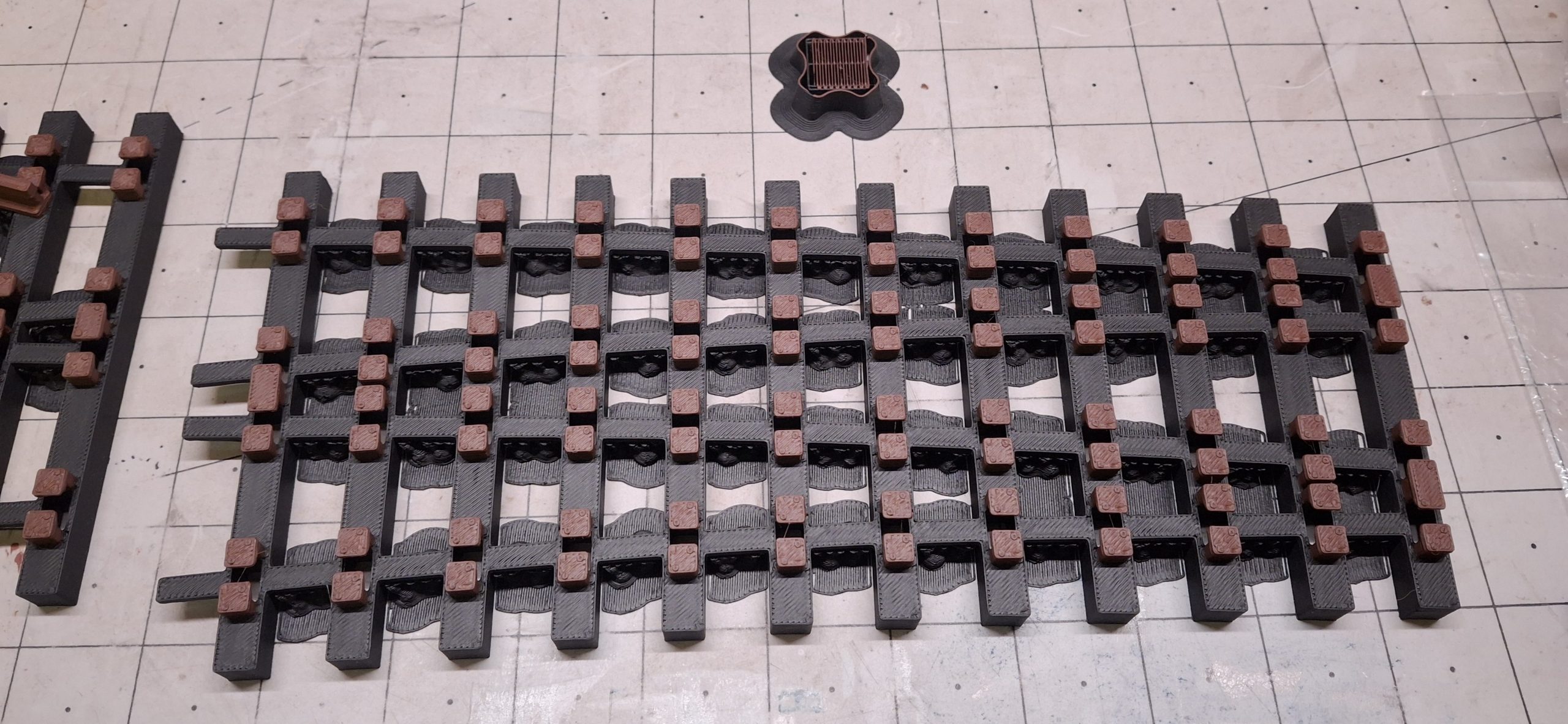
While that’s printing I’m test fitting the previous section, the closure rail tie strip, and run into a fitment issue with the last three ties before the frog section. Even though I centered the hold downs around the 14′ diameter stock rail in the design, they’re a very tight fit, like they’re offset too much toward the middle of the tie. I mark them with a red dot in the design to keep track of these fitment issues.
Test Fitting
I’m wondering if it’s just that one piece of rail that has an excessive bend at the end, but then how did it fit through all the rest of the ties with no problem? Why these last three ties? We’ll just keep that in our back pocket for now. This is just the prototype, and only the second iteration for that matter. I did find two other oversights that I’ve already corrected though.
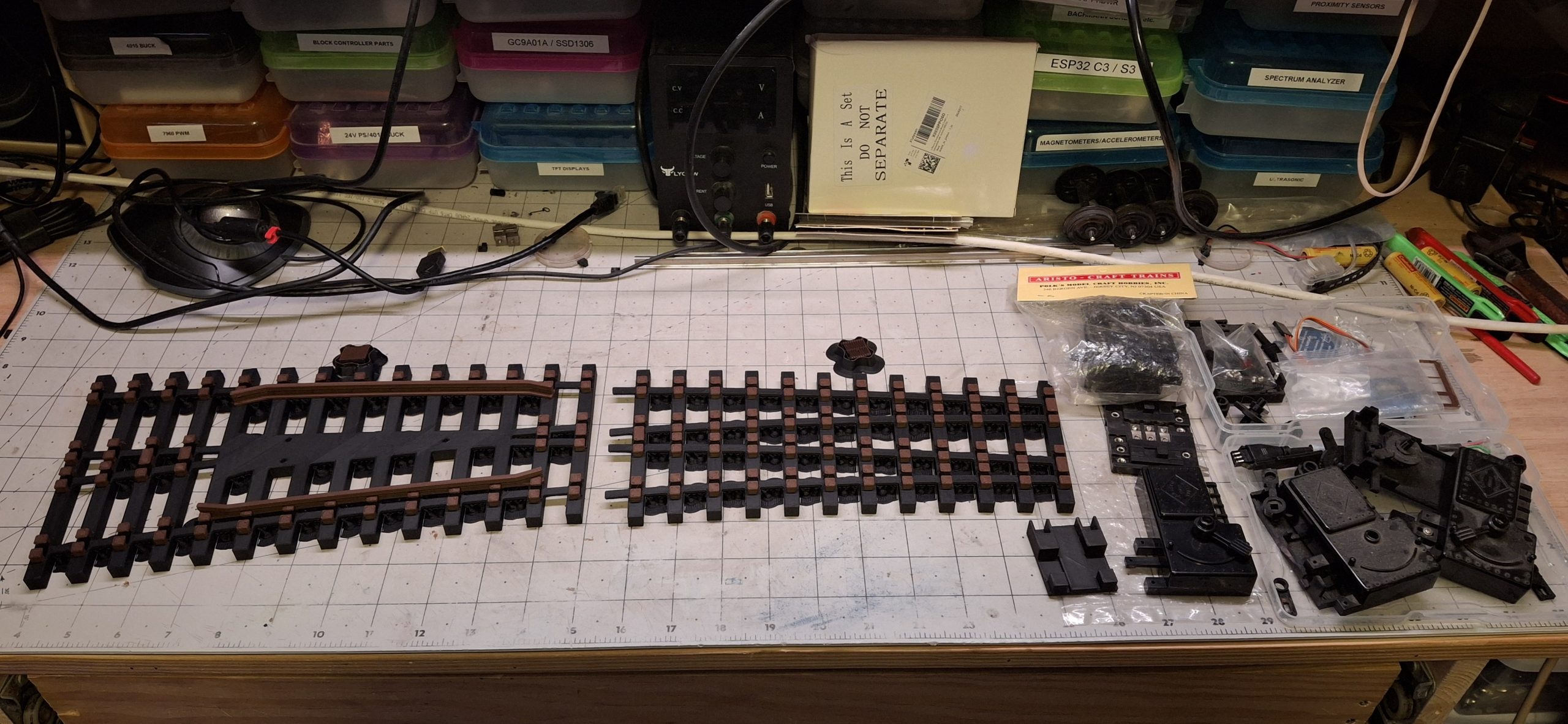
One is a missing strip section between ties and the other a missed section of a tie on the end to finish making it solid. Not bad for a prototype, and that’s what this stage of development is for, to catch any hiccups before devoting to production… with a whopping production volume of one. Maybe two if I make a mirror image and use it on the other leg of the wye.
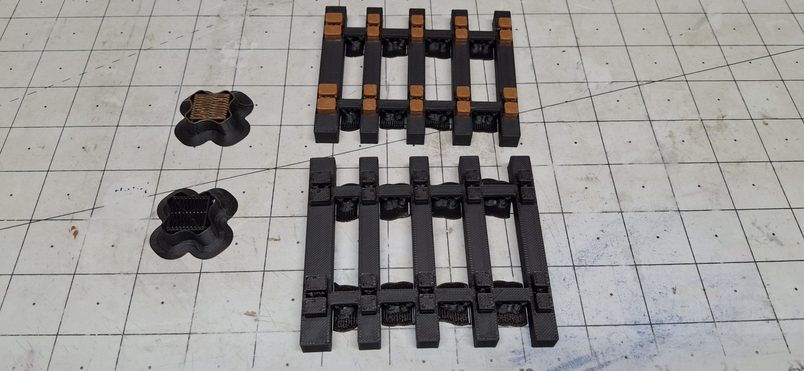
After allowing the frog tie section to cool when it finishes printing, the test fitting continues. The rails slide right in with ease, through all the tie strip sections, with the one exception of the closure section already mentioned. The rails fit snugly, yet loose enough to easily assemble. The redesign paid off. Totally worth the days of effort!
Next Steps
I’m impressed with the new printer. Only had one issue with it so far, and a self-inflicted one at that, a clogged nozzle. It’s my fault for using that old brown filament that’s been sitting out collecting moisture and dust, a surefire way to clog a nozzle. The filament became very brittle toward the end of the spool and ended up leaving broken pieces throughout the system when rewinding it.
At least now I know where to look for filament issues, how to take everything apart, and how to resolve them in the future. I ordered a couple replacement nozzles just in case a future clog can’t be cleared. It was a frustrating couple of hours though while I struggled to figure it out. Hours better devoted to redesigning and printing the latest iterations.
Next is testing multi-color printing. The multi-color slicing by height feature works well. And it’s all automatic! No pausing mid print to manually swap filament then resume. I may want to adjust the “flushing volumes”, if that’s even possible. That’s the amount of plastic “pooped” out to be sure the previous color is flushed and replaced with the next color before printing with it.
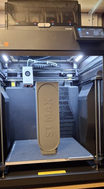
Thankfully AnyCubic was kind enough to include the print files for a “poop bucket” in the printer’s memory so I didn’t have to design it myself. It’s HUGE! It takes up nearly the entire print height and used more than half a 1kg spool of filament! But now I don’t have to worry about the piles of plastic poop accumulating on, around, and under the old printer anymore. It can make quite a mess.
Decisions, Decisions
Only ten days in, that’s where we’re at with our curved switch. All that’s left is “finessing” the rails to the proper lengths and shapes. I’ll need to bend a set of rails to the proper radii to start with. The stock rails are fairly simple, but the remaining rails need cut to size for the point, closure, and frog sections. Then grinding the point and stock rails to size. Lots of fun… Not!
I’m already thinking about how to go about that rail shaping. I don’t have a wheel or belt grinder. A Dremel with the proper grinding stones is about the only thing I have on hand. There’s still so much work to do in the garage to make space for anything on any bench that my options are limited for now.
Buying a new belt grinder makes sense for production quantities, but until I have the bench space for it, where to put it is the bigger issue. Almost the same issue for the Dremel drill press, except it’s more about getting to it. It’s sitting on the bench behind all the stuff that has to move somewhere else just to gain access to it. Either way there’s some bench cleanup in my very near future.
With any grinding option I’m thinking that a jig, or jigs, to hold and guide the rails would help ease the task of shaping them. The point rails need a good bit of material removed from the side that meets the stock rails. And the stock rails will need the foot removed on the point side to allow the point rail to snug up to it when that route is selected.
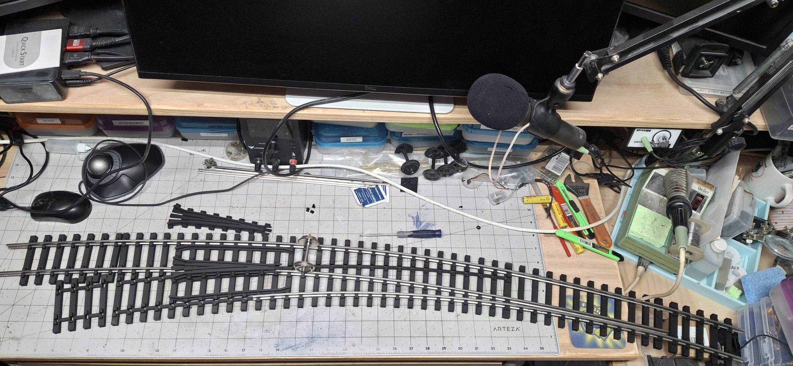
Grooming The Rails
Speaking of point rails, I need to modify the design to remove the ends of the ties around the throw bar and add mounting holes for the switch machine. Essentially make them hollow on the ends again, enough for the mounting brackets from the switch machine to fit and secure them with screws. Another option would be to just print the mounting bracket as part of the ties themselves.
I like the latter option better, more like prototypical headblocks, with the switch machine mounting hardware to secure it at the headblock ties’ ends, and no supports to remove. But I’m getting ahead of myself again. We’ll come back to this later. Until I have room for that new belt grinder, I can still bend the rails to the correct curvature and use the Dremel saw to cut them to length.
Up until now I’ve been using the rails from Aristo-craft 14′ and 20′ diameter curve sections with the their tie strips removed to test the fit. Time to switch to the actual rails we’ll be using. There’s still plenty of flex track rail left from our last day trip over to Pinellas Park, maybe 50′ of track, or 100′ of rail. Each rail is 10′ long, so two should be enough for the switch with some to spare.
Rough math says two 4′ long sections of track, one for each route. That’s roughly two 8′ long pieces, with maybe ~2′ leftover from each 10′ rail? The stock rails are easy to figure, and the Aristo-craft 20′ diameter curve outside rail provides an accurate template. The 14′ stock rail is more a “guestimate”, but the 20′ diameter curve inside rail is a close approximation, if not slightly too long.
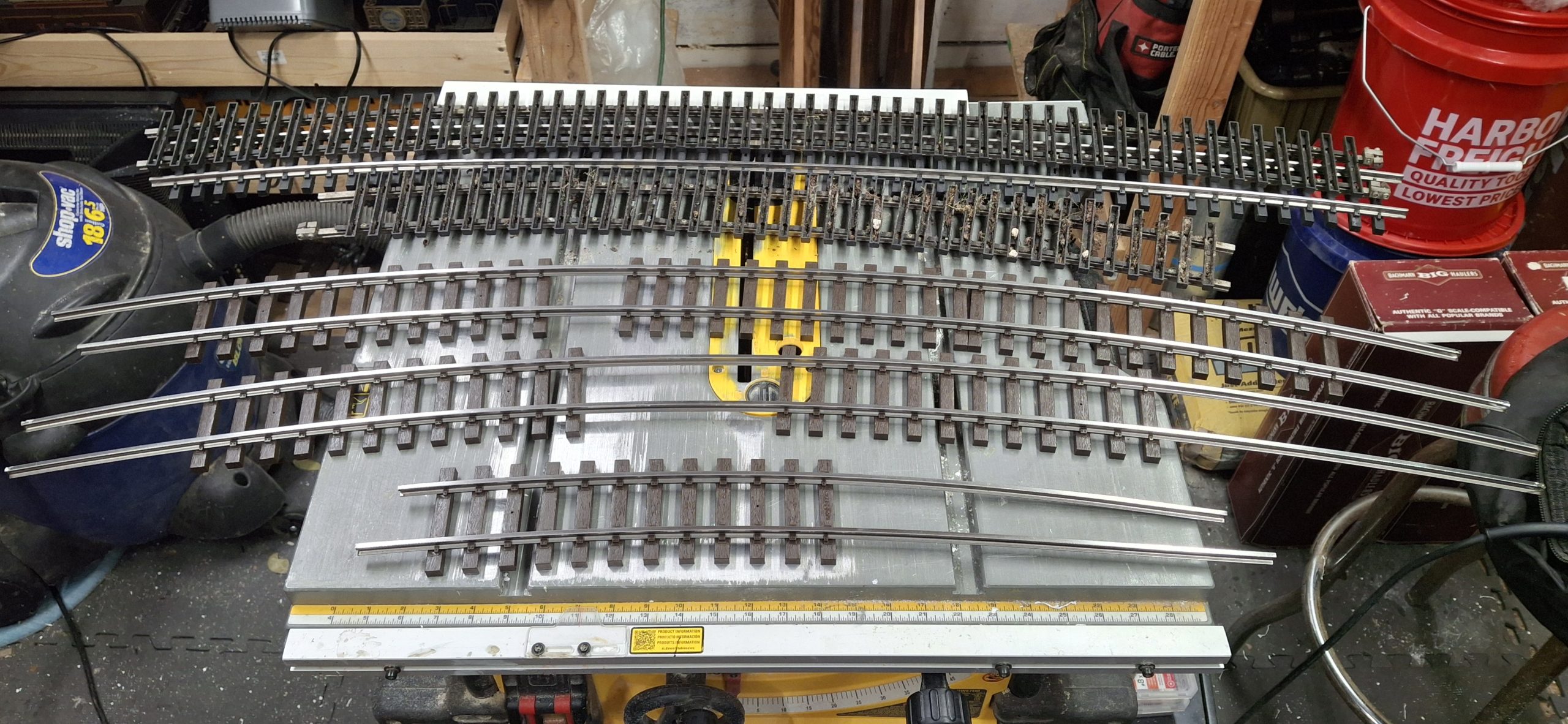
Bending The Rails
Before any rail is cut, it needs bent to the correct curvature. Using enough of the Piko flex track tie strips to hold the two rails together and the rail bender, they’re coerced into the 20′ diameter curvature to start with. Again, the Aristo-craft 20′ diameter curve section provides an accurate template to compare to while bending and measure against when cutting the rail to size.
Next are the 14′ diameter rails, then the closure and point rails, and lastly the frog rails. A quick deburring with the diamond file to avoid slicing fingers open on the sharp edges and the stock rails slide in nice and easy. The 14′ diameter stock rail doesn’t seem so snug where it did previously, but somehow I managed to cut the 20′ diameter closure rail too short!
Thankfully I made the frog removable, which allows the closure rails slide right in> Then the frog is fastened in place using three M2.5 screws. From there the frog rails and the diverging route tie strips. The point rails have a single hold down which acts as the hinge, or pivot point, of those rails. Without some means to hold them in place they keep falling out. Time to work on that throw bar.


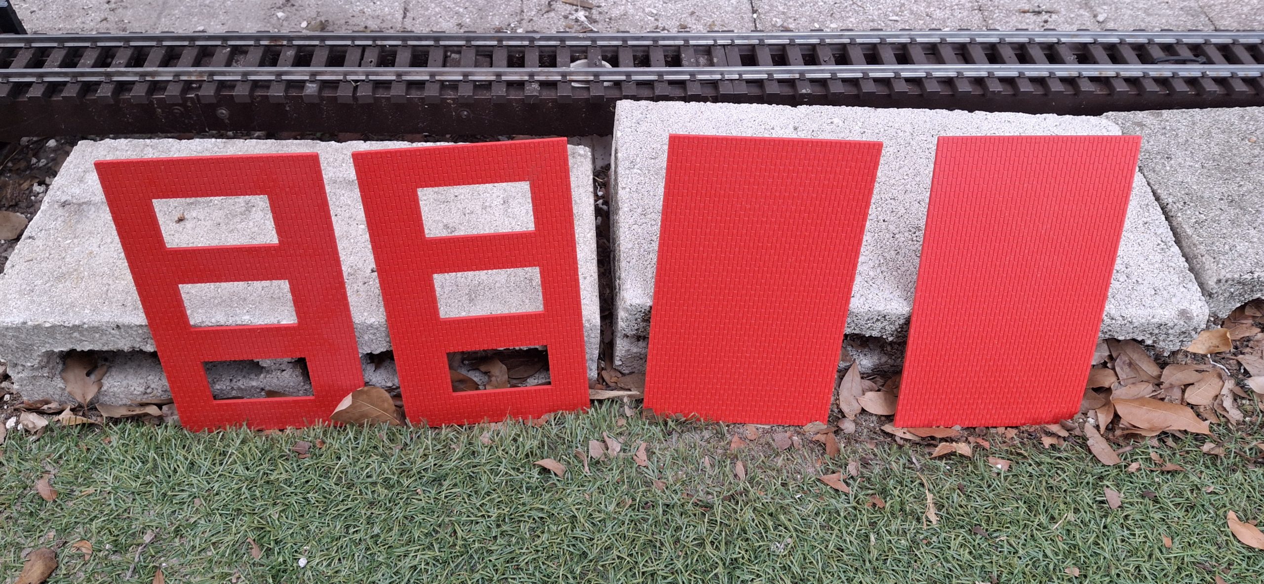
Honorable Mentions
There are a few things worth noting before diving into the next design modifications. First is the recent innovation of High Temperature PLA (HT-PLA) by PolyMaker and how it solves a key design limitation when 3D printing the curved switch parts, heat resistance. Standard PLA is no match for the Florida heat! Second is the foray into OpenSCAD.
PLA lasts only days before warping, as we found out the hard way with the Grand Hotel “skin”. We need a quick way to test this HT-PLA in the baking hot Florida sun. The quickest way there is to print something we’ve already designed, like one of those brick walls from the Downtown Marketplace storefronts. But instead of manually editing it to make it thicker, it’s time to try out OpenSCAD.
With the switch on the back burner until a decision on a grinder is made, time to look at new opportunities using the HT-PLA material. In all the discussion about FreeCAD vs. SketchUp, OpenSCAD was never mentioned. OpenSCAD is a way to programmatically design 3D models. All those tedious manual foot clamp changes could have been an easy change to a parameter in OpenSCAD.
To see more about how we tested HT-PLA and how we solved other problems for a number of mothballed projects waiting on a different solution, take a look at our cut stone retaining wall post.

A New Grinder
Getting back to that throw bar, we need the point rails and stock rails shaped to accurate place where the throw bar mounts to the point rails to provide the proper wheel flange clearance through the non selected route. How to mount the point rails is a different story. My thought is just use the Dremel drill press to drill holes in the foot of the point rails, tap, then secure with screws.
Nick has a lot of experience working with stainless steel and reminds me it requires slow speeds and heavy pressure. If anything the Dremel is high speed and low pressure. That works great for burrs and grinding stones, but not so much for drilling stainless. So much for that idea. At least I don’t have to worry about how to extricate it. The time has come for a new belt grinder.
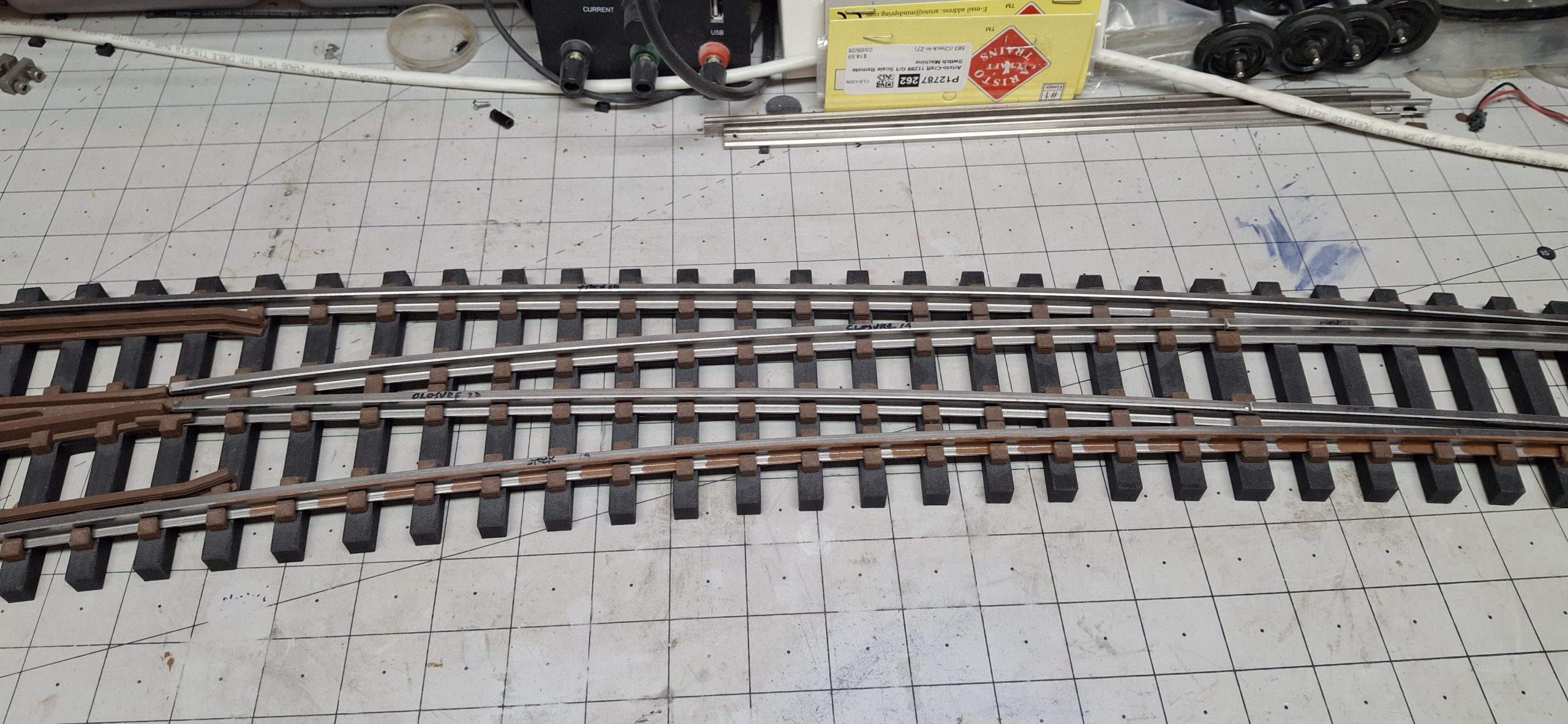
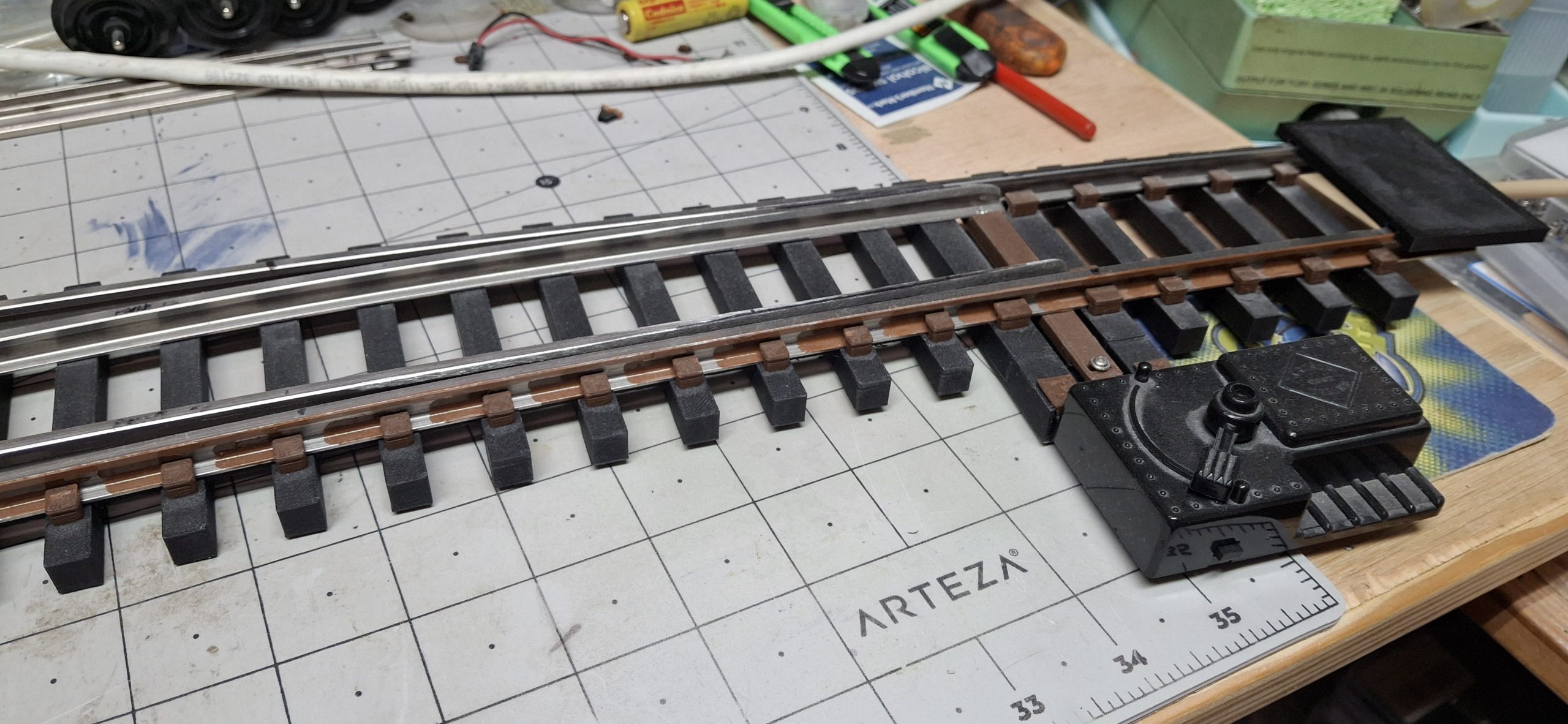
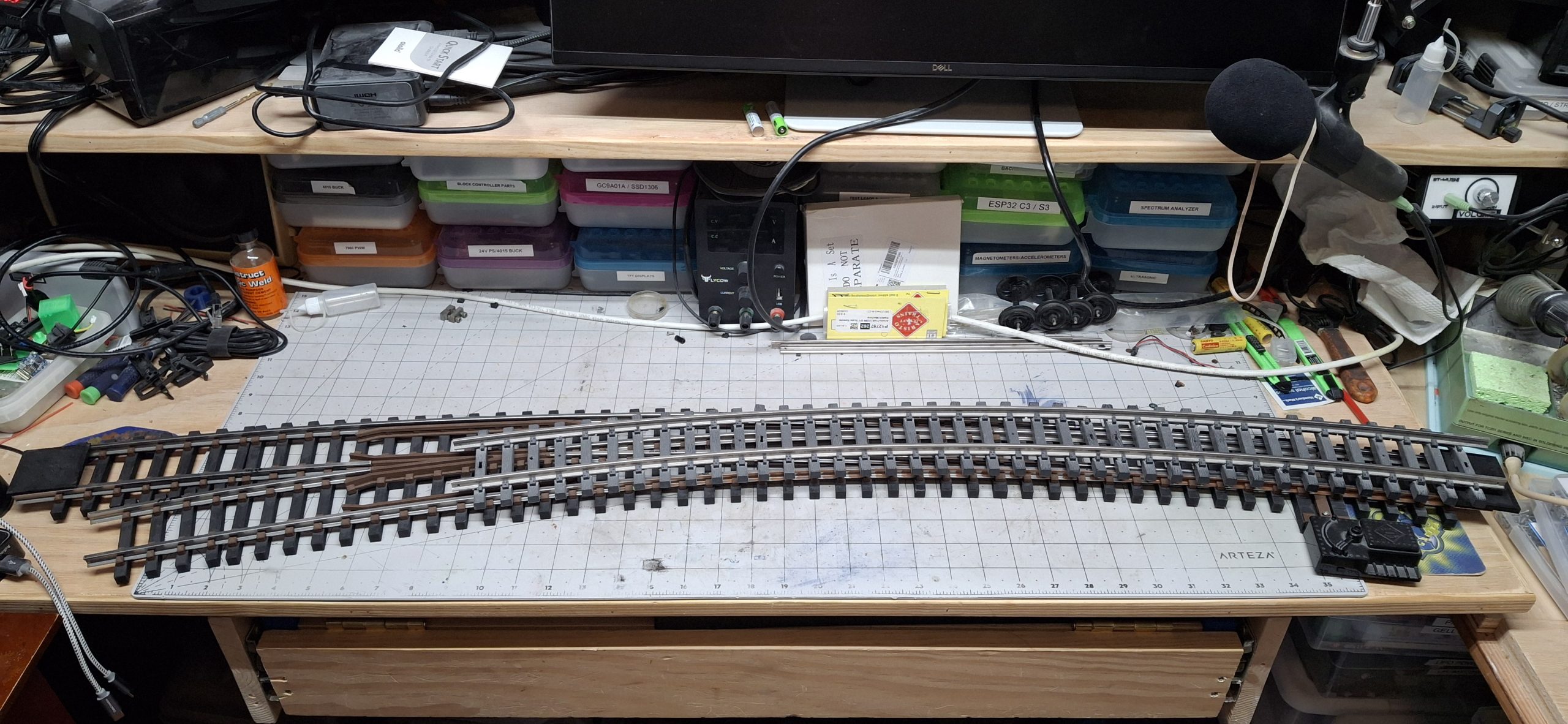
Quick trip to Harbor Freight finds a 4″x36″ belt grinder that will fit the bill nicely. Once home, it sat in the box for a day or two before I cleared a spot for it on the corner of the bench next to the table saw parking area. Definitely made quick work of shaping those rails, starting with the point rails. The only difficulty is getting close enough to make the sharp transition the stock rail’s foot.
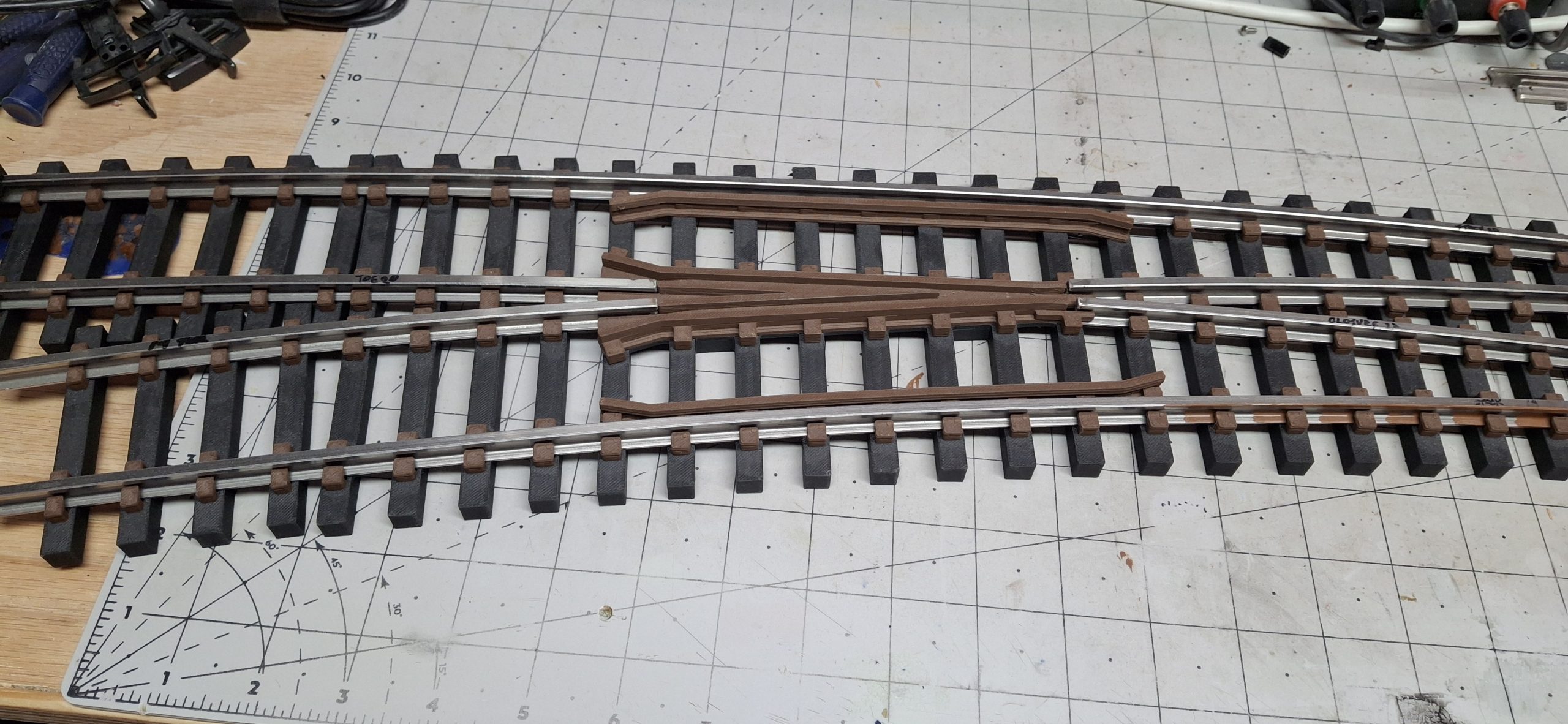
Finessing The Fiddly Bits
With that much said and done, the hard part is getting everything just right. The fit between the rails for the switch portion of the turnout takes some fiddling and finesse to get them finely tuned. Otherwise, the result is derailments as wheels “pick the points” and equipment ends up following both routes instead of the selected one.
Before we can even get to that point, we need a throw bar to secure the point rails together, yet space them apart by just the right amount. Again, just enough to clear the wheel flange through the non selected route. It takes quite a few iterations just to get those dimensions correct. Next thing that needs figured out is how to secure the point rails to the throw bar.
The Aristo-craft switches have a hole drilled and tapped into the web of the point rails to accept a 2mm machine screw. The screws pass through the throw bar and secure it to the the point rails. Originally I thought about doing something similar, purchasing the tap and correct drill size to do so.
But as Nick had said, using that high speed Dremel tool is a sure way to work harden the stainless steel and snap the drill bit right off. Last thing I want to do is bend more rail, cut it to size, and grind to fit a point rail all over again. Out of curiosity, I try using the 1⁄16″ hex shank drill bit by hand. Can’t go much slower than that! Pressing hard and working slowly does the trick.
Adding A Switch Machine
In no time at all both point rails are drilled. But rather than go into the web, I just drilled through the foot. There’s not enough “meat” there to rely on tapping the hole, so I used self tapping screws. Although they’re not really meant for metal, they work well enough to capture the point rails and secure them to the throw bar. Getting the placement and relief right takes a few more iterations.
Moving on to the switch machine and how to mount it. Because the switch machine itself secures the headblock ties at the proper distance apart, originally I was thinking about just modifying the design to remove the mount points from the two tie strips and incorporate both together as a single, separate unit. It would actually be two designs, one for inside throw and one for outside throw.
That way the only mounting hardware is on the switch machine itself. I opted for a compromise design that requires just a single adapter and can be “press fit” from beneath into recesses in the headblock ties. That way it can rotated to the proper orientation no matter what side the switch machine mounts to and the benefit of mounting hardware on just the switch machine itself remains.
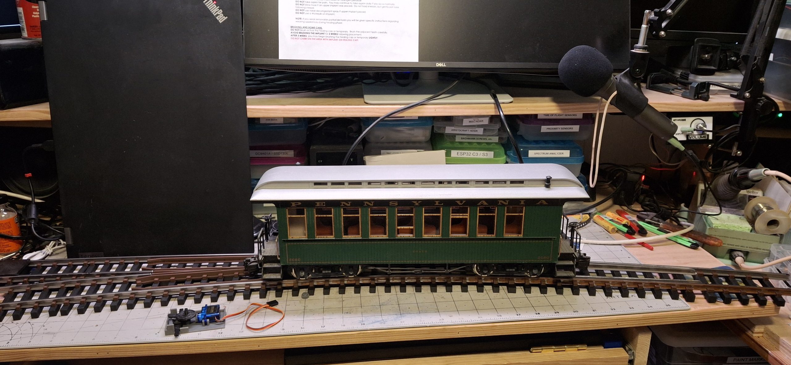
As always, that design takes a number of iterations to get everything just right too. Using a standard Aristo-craft manual switch machine, that familiar over center “snap” action is now selecting which route through our curved turnout! Started testing clearances by running a single wheel set through each route then graduated to using an old style passenger car. It passes with flying colors!
It’s A Big Un!
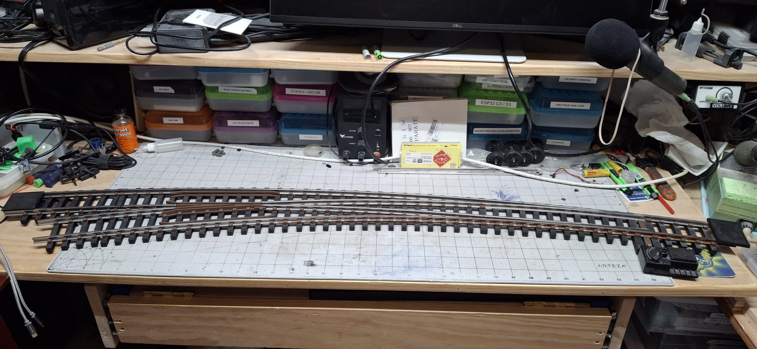
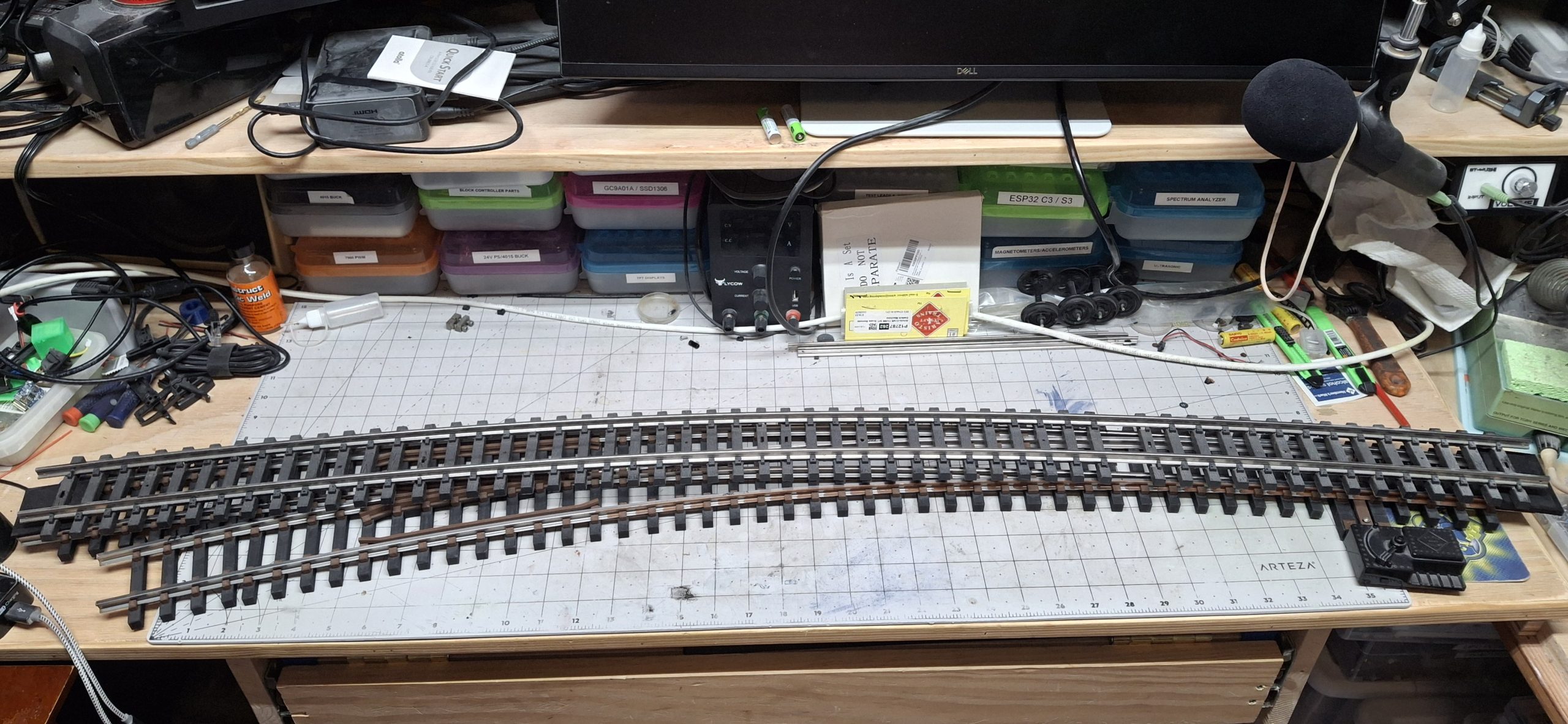
If you think the 3′ long #6 and wye switches are impressive, you should see my 4′ long (~122cm) curved switch! My first rough estimate puts the frog somewhere between a #5 and #6. But it’s a curved frog, not straight, making it difficult to tell exactly what the “rise over run” values are. It does resemble the #6 frog fairly closely, so probably closer to a #6.
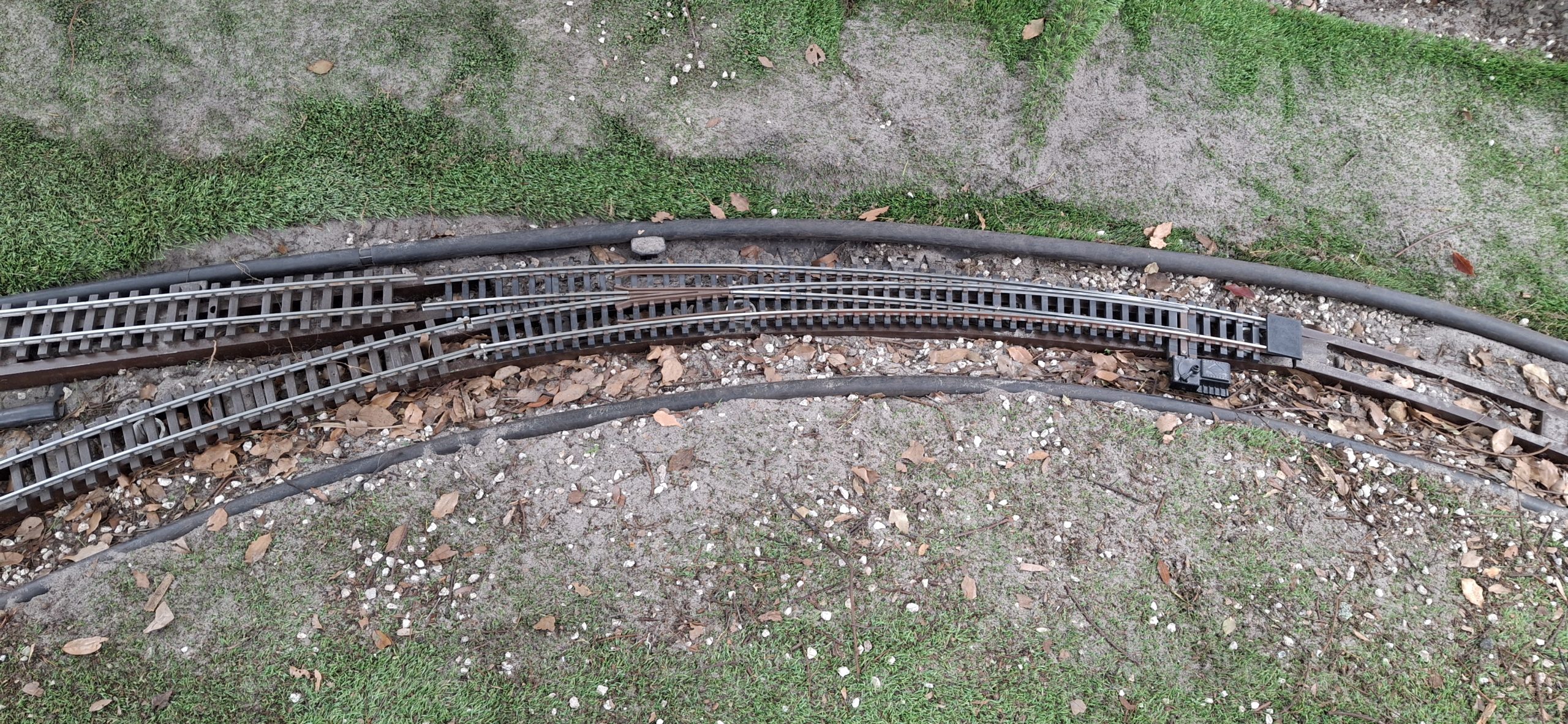
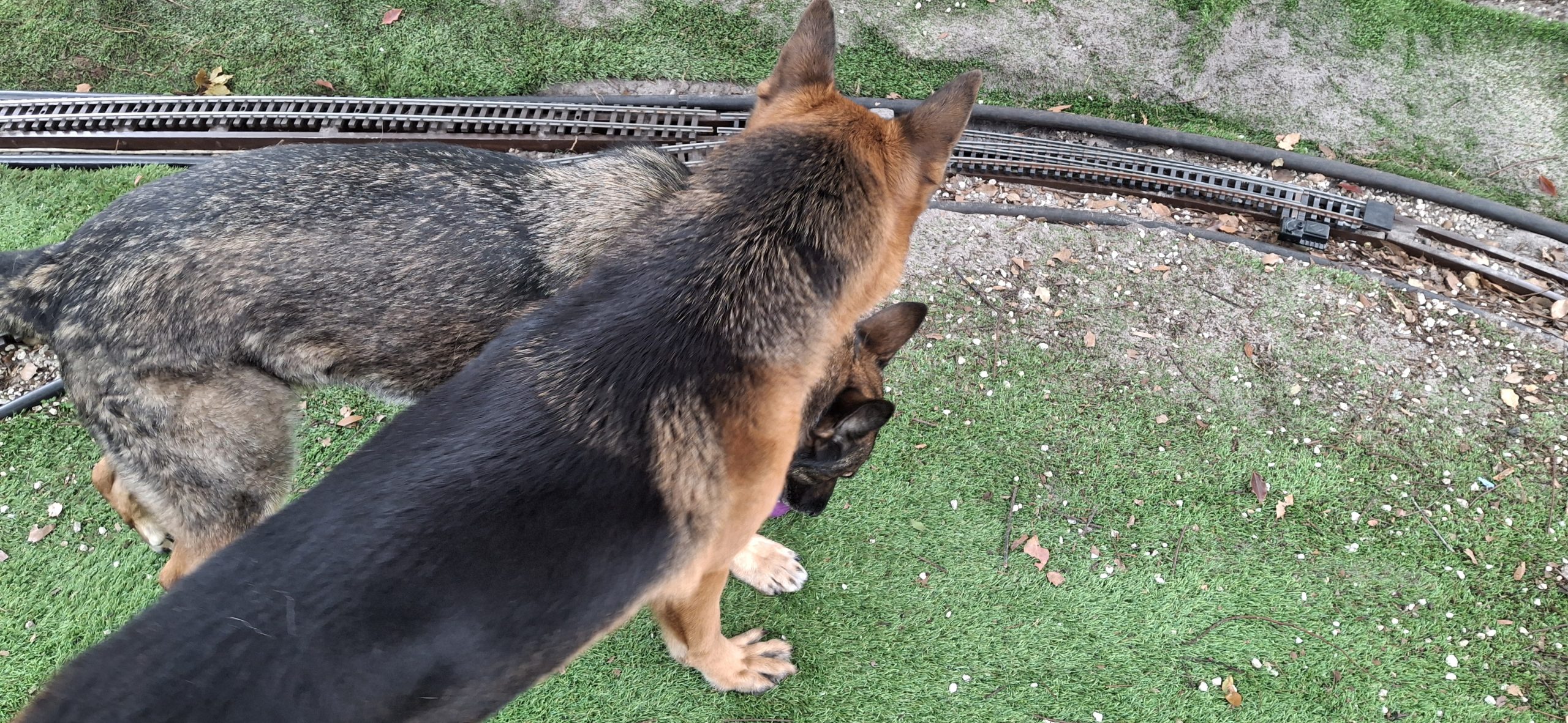
It’s a bit unwieldy and getting it from the workbench and out the back door to the wye was a real feat, but it fits like a glove! Perfect! Can’t wait to see whether it works or just derails everything. That depends a lot of on how well it stands up to the pups pounding on it when chasing the ball or the occasional squirrel that has the audacity to try to run along the top of the new fence.
It’s designed to be a “drop in” replacement of an Aristo-craft 20′ diameter curved section and that’s exactly how it fits. Just need to perfect those double insulated rail joiners and we’ll be all set to test the operation. At least manually. It’s going to take a bit more effort to actually get the trains running again and subject it to the true test.

Next Steps
You may ask why I don’t just buy some insulated SplitJaw clamps. At $13 plus shipping for two stainless steel insulated clamps, that gets real expensive real quick. Granted, I can get ten for $30, but compared to $300 for 60 standard clamps, $3 vs. $5 per clamp, it seems like a good deal all of a sudden. I have access to milling equipment, so I may end up making my own.
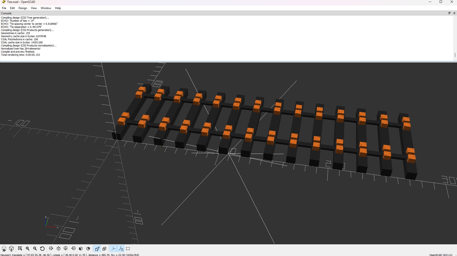
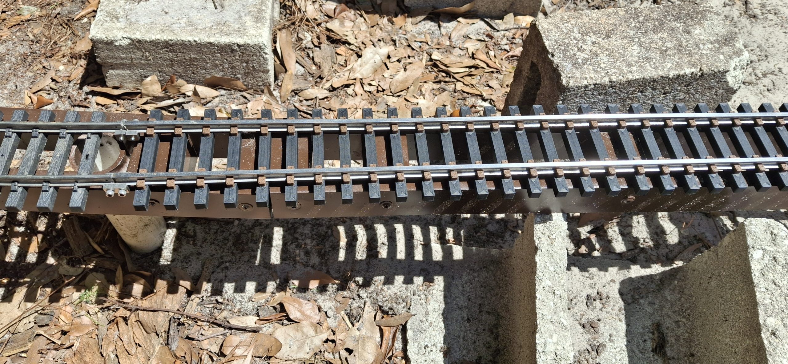
They don’t make insulated double length rail clamps, so I’ll just print the insulated part and use parts from the standard clamps to make my own. While I’m tinkering with those, I take another foray into OpenSCAD, this time to create replacement tie strips. OpenSCAD is covered in more detail in our cut stone retaining wall post. Check it out if you’re interested. Now back to the story…
A box of twenty-five Piko11″ tie strips is around $125. That’s ~$5 each! I calculated 3D printing our own at ~$2 each, but let me check my math on that one. If we can print twenty-five of them from a single 1kg spool of filament costing $25, that’s $1 each. Two spools => $2 each. etc. The slicer says 88.53g of filament, or a little over 11 per spool, so $2.22 each. On sale at $20, that’s $1.76 each.
Beyond all that, there’s more work to do to get to a final product. Once we have trains running again, we’ll see if the prototype switch can withstand the true test. Will it hold up or fall apart? What else needs done to make this a reliable part of our Barkyard RR? We’ll find out soon enough. Spoiler alert, we cover running trains in our final installment of replacing stringers.
Disclaimer – Not Sponsored
I should mention that the Barkyard is not sponsored by AnyCubic, PolyMaker, Elegoo, Sunlu, or any of the host of other manufacturers of 3D printers and filament or any other entities, like Harbor Freight. I don’t think they’d care much for my nicknames for them anyway, like Horrible Freight, Hazard Fraught, etc. No freebies or evaluation promotions here. This is all paid for out of pocket.
Question? Concerns? Leave A Comment!
If you’re interested in obtaining the STL files to print your own curved switch, leave us a comment and we’ll be happy to provide them to you. Also, if you have any other questions or concerns, please feel free to comment on this post. In any case, you’ll need to create a user account to do so. We don’t use any personal information for marketing or to spam you (see our privacy policy). You’ll receive a verification email. Reply to the link provided to verify your email address. It’s all automatic. No waiting on moderator approval! No spamming your inbox with useless advertisements and “Special Offers”. None of that nonsense. We do it this way to prevent bots and spammers from detracting from your experience.
More to come. Stay tuned!